

過酷な軍事環境に耐える空圧部品を探すのに苦労していませんか?多くのエンジニアは、商用グレードのシリンダーが戦場の状況にさらされたときに致命的な故障を起こし、ミッションクリティカルなシステムの故障や生命を脅かす可能性のある状況につながることを発見するのが遅すぎました。
軍用 空気圧シリンダー は、GJB150.18衝撃試験(100gの加速度パルスに耐えることが要求される)、80~100dBの電磁干渉保護を提供するEMIシールド・エンクロージャー、-55℃~+125℃の温度範囲で機能を維持しながら1,000時間以上の塩水噴霧に耐える包括的な「スリープルーフ」コーティング・システムなどの厳しい基準を満たす特殊な設計により、極限状態に耐えるように設計されています。
目次
- GJB150.18衝撃試験はどのように戦場での信頼性を確保するのか?
- 現代の軍事システムにEMIシールドが不可欠な理由とは?
- どの防錆コーティング・システムが真のミリタリーグレードの保護を提供するか?
- ロッドレスシリンダーは空母のカタパルトシステムでどのように使われているか?
- 結論
- 軍用空気圧シリンダーに関するFAQ
GJB150.18衝撃試験はどのように戦場での信頼性を確保するのか?
軍用機器は、爆発、武器の発砲、荒れた地形、ハードな着陸など、標準的な市販部品では破壊されてしまうような極度の機械的衝撃に耐えなければならない。
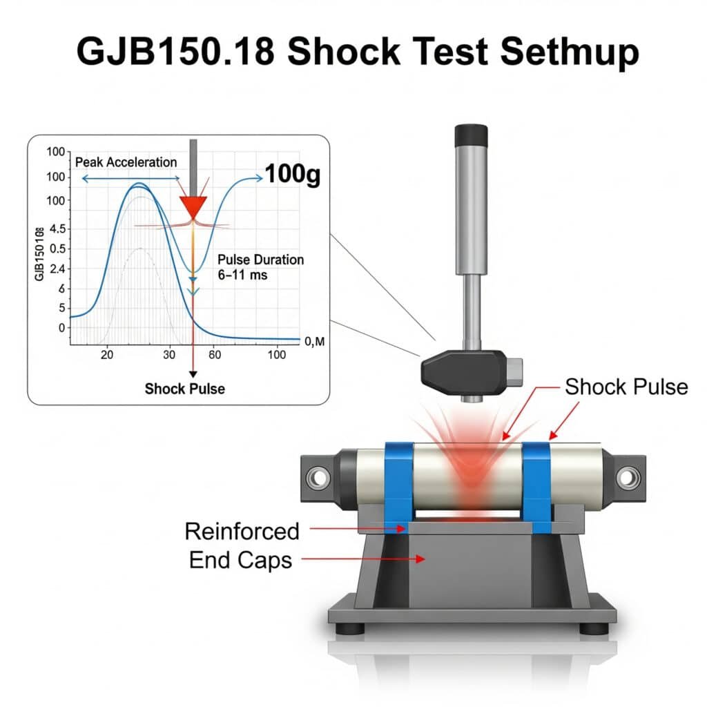
GJB150.18 衝撃試験規格1 は、100g(981m/s²)に達する精密制御の加速度パルスを、複数の軸にわたって6~11msの継続時間で空気圧シリンダーに与えます。ミリタリーグレードのシリンダーは、これらの試験後も完全な機能を維持する必要があり、強化されたエンドキャップ、衝撃吸収クッション、戦場での衝撃による致命的な故障を防ぐ固定された内部部品など、特殊な内部設計が要求されます。
主要テスト・パラメーター
| パラメータ | 必要条件 | 市販同等品 | ミリタリー・アドバンテージ |
|---|---|---|---|
| ピーク加速度 | 100g (981 m/s²) | 15~25g(147~245m/s²) | 4~6倍の耐衝撃性 |
| パルス持続時間 | 6-11ms(ハーフサイン) | 15-30ms(テスト時) | 戦場での衝撃をより鋭くシミュレート |
| 影響数 | 合計18本(各方向3本ずつ、6方向) | 合計3-6(テスト時) | 多軸耐久性を確保 |
| 機能テスト | ショック時およびショック後 | ショック後のみ(テスト時) | リアルタイム動作の検証 |
海軍の防衛請負業者は、ミサイル装填システムの工業用シリンダーが、荒海でわずか30gの衝撃を受けただけで内部部品が故障した事例を記録している。GJB150.18に適合した軍用シリンダーで再設計した後、これらのシステムは、80gを超える衝撃の模擬戦闘条件下でも完璧な機能を維持した。
重要な設計要素
強化エンドキャップ
- 厚みの増加:商業規格の2.5~3倍
- ネジ切りを強化:150-200% より深いネジ山
- その他の保持機能安全ワイヤーホール、ロック機構内部コンポーネントの固定
- ピストンとロッドの接続:メカニカルロックと圧入の比較
- スレッドロックコンパウンド軍用仕様の嫌気性接着剤
- 冗長保持:重要部品のセカンダリー・メカニカル・ロック衝撃吸収機能
- クッション性を強化:クッション長延長(市販品200-300%)
- プログレッシブ・クッショニング:多段階減速プロファイル
- クッション素材:エネルギー吸収性の高い特殊ポリマー構造補強
- より厚いシリンダー壁:市販厚の150-200%
- マチ付きの取り付け機能強化マウントポイント
- ロッド径アップ市販同等品の130-150%
衝撃故障解析
| 故障モード | 商業的失敗率 | 軍用グレードの緩和 | 効果 |
|---|---|---|---|
| エンドキャップ排出 | 高い(一次故障) | メカニカルロック、スレッドの噛み合い増加 | >99%還元 |
| ピストン・ロッド分離 | 高い | 機械的インターロック、溶接アセンブリ | >99%還元 |
| シール押出 | ミディアム | 強化シール、押し出し防止リング | 95%リダクション |
| ベアリングの変形 | ミディアム | 硬化素材、サポートエリアの拡大 | 90%リダクション |
| 取り付けの失敗 | 高い | ガセット・マウント、ボルト・パターン拡大 | >99%還元 |
現代の軍事システムにEMIシールドが不可欠な理由とは?
現代の戦場環境は、繊細な電子システムを混乱させたり損傷させたりする可能性のある電磁信号が飽和状態にあるため、電子インターフェースを持つ空気圧部品には特殊な保護が必要です。
電子部品を搭載した軍用空気圧シリンダーには、10kHz~10GHzの周波数帯域で80~100dBの減衰を実現するEMIシールド筐体が必要です。これらの特殊な設計には ファラデーケージの原理2 導電性素材、特殊なガスケット、フィルター付き接続を使用し、電磁干渉と、作戦の安全性を損なう可能性のある信号傍受の両方を防ぐ。

EMIの脅威源と影響
| EMIソース | 周波数範囲 | フィールド強度 | 空気圧システムへの潜在的影響 |
|---|---|---|---|
| レーダーシステム | 1-40 GHz | 200+ V/m | センサーの誤作動、制御の乱れ |
| 無線通信 | 30 MHz-3 GHz | 50-100 V/m | 信号破損、誤トリガー |
| EMP兵器3 | DC-1 GHz | 50,000 V/m 以上 | 電子機器の完全故障、データ破損 |
| 発電 | 50/60 Hz | 強磁場 | センサーの干渉、位置エラー |
| 雷/静電気 | DC-10 MHz | 極端な過渡現象 | コンポーネントの損傷、システムのリセット |
ミサイル防衛システム・メーカーは、レーダー作動中に位置フィードバック・シリンダーに断続的なエラーが発生するケースを記録してきた。調査の結果、レーダーパルスがセンサー配線に電流を誘導し、最大15mmの位置報告誤差を引き起こしていることが判明しました。85dBの減衰を持つ包括的なEMIシールドを実装することで、これらの干渉問題は完全に排除され、レーダーのアクティブ動作中でも0.05mm以内の位置精度を達成しました。
重要な設計要素
素材の選択
- 導電性ハウジング材料(アルミニウム、スチール、導電性複合材料)
- 表面導電性向上(メッキ、導電性コーティング)
- 磁気シールドにおける透磁率の考慮縫い目と継ぎ目の処理
- すべての継ぎ目で連続的な電気接触
- 圧縮永久歪とガルバニック相溶性に基づく導電性ガスケットの選択
- ファスナー間隔(最高周波数では通常λ/20)侵入管理
- フィルター付き電気接続(フィードスルーコンデンサー、PIフィルター)
- 必要な開口部のための導波管-ベローカットオフ設計
- ケーブル・エントリー用導電性グランドグラウンド戦略
- 周波数に基づく一点接地と多点接地
- 接地面の実装
- ボンディング抵抗仕様(<2.5 mΩ標準)
素材性能の比較
| 素材 | シールド効果 | 体重への影響 | 耐食性 | ベスト・アプリケーション |
|---|---|---|---|---|
| アルミニウム(6061-T6) | 60~80 dB | 低い | 治療との相性が良い | 汎用、重量に敏感 |
| ステンレススチール(304) | 70-90 dB | 高い | 素晴らしい | 腐食環境、耐久性 |
| ミューメタル | 100+ dB(磁気) | ミディアム | 中程度 | 低周波磁場 |
| 導電性シリコーン | 60~80 dB | 非常に低い | 素晴らしい | ガスケット、フレキシブルインターフェース |
| 銅箔 | 80-100 dB | 低い | コーティングなし | 最も高い導電性が必要 |
空気圧アクチュエータを使用する海軍火器管制システムは、耐腐食性とEMIシールドのバランスを慎重にとる必要があります。軍事エンジニアは、銀メッキのベリリウム銅ガスケットを備えた316ステンレススチールのエンクロージャーを選択することが多く、塩水噴霧環境で完全な機能を維持しながら、平均92dBの減衰を達成しています。
どの防錆コーティング・システムが真のミリタリーグレードの保護を提供するか?
軍用空気圧システムは、砂漠の暑さから北極の寒さまで、塩水にさらされ、化学的脅威にさらされ、標準的な市販の仕上げを急速に破壊するような研磨条件に至るまで、過酷な環境で作動しなければならない。
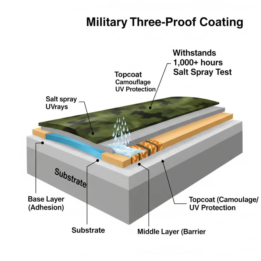
軍用グレードの空気圧シリンダー用「3プルーフ」コーティング・システムは、複数の特殊な層を組み合わせています。接着と初期耐食性のためのクロメート化成またはリン酸塩ベース層、化学的および湿気バリア特性を提供する高ビルドのエポキシまたはポリウレタン中間層、カモフラージュ、低反射性、追加の化学的保護を追加する耐紫外線トップコートで構成され、1,000時間以上の塩水噴霧試験に耐えます。
保護カテゴリー
耐湿性/耐腐食性
- 耐塩水噴霧性(1,000時間以上/回 ASTM B1174)
- 耐湿性(高温時95% RH)
- 浸水能力(淡水および海水)耐薬品性
- 燃料と作動油の適合性
- 除染液耐性
- 潤滑油の適合性環境耐久性
- 耐紫外線性
- 極限温度(-55℃~+125)
- 耐摩耗性と耐衝撃性
中東での軍事配備評価では、標準的な工業用シリンダーと、包括的なコーティングシステムを備えた軍用ユニットが比較された。塩分を含んだ空気と砂の摩耗がある砂漠の環境にわずか3ヶ月間置かれただけで、市販のシリンダーは著しい腐食とシールの劣化を示した。防錆コーティングを施した軍用シリンダーは、同じ環境下で2年間使用しても、わずかな外観上の摩耗が見られるだけで、完全に機能する状態を維持した。
レイヤーの機能と性能
| レイヤー | 主要機能 | 厚さ範囲 | 主要物件 | 申込方法 |
|---|---|---|---|---|
| 前処理 | 表面処理、初期腐食保護 | 2-15μm | 接着促進、化成処理 | 薬品浸漬、スプレー |
| プライムコート | 接着、腐食抑制 | 25-50μm | バリア保護、抑制剤放出 | スプレー、電着 |
| 中間コート | 厚み、バリア性 | 50-100μm | 耐薬品性、衝撃吸収性 | スプレー、ディップ |
| トップコート | UVカット、外観、特性 | 25-75μm | カラー/グロスコントロール、特殊な耐性 | スプレー、静電 |
ミッドレイヤーの性能比較
| コーティング・タイプ | 塩水噴霧耐性 | 耐薬品性 | 温度範囲 | ベスト・アプリケーション |
|---|---|---|---|---|
| エポキシ(ハイビルド) | 1,000~1,500時間 | 素晴らしい | -40°C~+120°C | 汎用 |
| ポリウレタン | 800~1,200時間 | 非常に良い | -55°C ~ +100°C | 低温 |
| 亜鉛リッチエポキシ | 1,500~2,000時間 | グッド | -40°C ~ +150°C | 腐食性環境 |
| CARC | 1,000~1,500時間 | 素晴らしい | -55°C ~ +125°C | 化学物質脅威地域 |
| フッ素樹脂 | 2,000時間以上 | 傑出している | -70°C ~ +200°C | 過酷な環境 |
空気圧アクチュエータを備えたミサイル発射システムのために、軍事エンジニアは、亜鉛リッチエポキシプライマーとCARCトップコートの特殊コーティングシステムを実装しています。これらのシステムは、2,000時間以上の塩水噴霧試験後も完全な機能を維持し、化学兵器模擬物質に対する耐性を実証しています。
環境性能の比較
| 環境 | 商業コーティングの寿命 | 軍隊生活 | パフォーマンス比率 |
|---|---|---|---|
| 砂漠(暑い/乾燥している) | 6-12ヶ月 | 5~7年以上 | 5-7× |
| トロピカル(高温/多湿) | 3-9ヶ月 | 4~6年以上 | 8-12× |
| マリン(塩分暴露) | 2-6ヶ月 | 4~5年以上 | 10-15× |
| アークティック(極寒) | 12~24カ月 | 6~8年以上 | 4-6× |
| バトルフィールド(複合) | 1~3ヶ月 | 3~4年以上 | 12-16× |
ロッドレスシリンダーは空母のカタパルトシステムでどのように使われているか?
空母カタパルトシステム5 空気圧技術にとって最も要求の厳しいアプリケーションのひとつであり、卓越したパワー、精度、信頼性が要求される。
航空母艦のカタパルトシステムは、航空機発進機構の重要なコンポーネントとして、特殊な高圧ロッドレスシリンダーを利用している。これらのシリンダーは、約90メートルの甲板長をわずか2~3秒で戦闘機を0~165ノット(時速305キロ)まで加速させるのに必要な大きな力を発生させるため、空気圧部品は極度の圧力、温度、機械的ストレスにさらされる。

ロッドレス設計の主な利点
| 特徴 | カタパルト・システムのメリット | ロッドシリンダーとの比較 |
|---|---|---|
| スペース効率 | 全ストロークがデッキの長さに収まる | ロッドシリンダーは2倍の設置スペースが必要 |
| 重量配分 | バランスのとれた可動質量 | ロッドシリンダーの質量分布は非対称 |
| 加速能力 | 急加速に最適化 | ロッド座屈の懸念によるロッドシリンダーの制限 |
| シーリング・システム | 高速運転に特化 | 標準的なシールは打ち上げ速度で故障する |
| フォース・トランスミッション | シャトルに直接連結 | ロッドの設計には複雑な連結が必要になる |
代表的な性能パラメータ
| パラメータ | 仕様 | エンジニアリング・チャレンジ |
|---|---|---|
| 動作圧力 | 200~350バール(2,900~5,075psi) | 超高圧封じ込め |
| ピーク・フォース | 1,350kN以上(300,000ポンド以上) | 歪みのない力の伝達 |
| 加速度 | 最大4g (39 m/s²) | 制御された加速プロファイル |
| サイクルスピード | 発射間隔45~60秒 | 迅速な圧力回復 |
| 運用信頼性 | 99.9%+の成功率が必要 | 故障モードの排除 |
| 耐用年数 | オーバーホール間隔5,000回以上 | 高速走行時の摩耗の最小化 |
重要な設計要素
シーリング技術
- 金属エナジャイザー付きPTFEベース複合シール
- 圧力ステージングによる多段シールシステム
- 熱管理のためのアクティブ冷却チャンネル馬車デザイン
- 航空宇宙グレードのアルミニウムまたはチタン構造
- 統合エネルギー吸収システム
- 低摩擦ベアリング・インターフェースシリンダーボディの構造
- オートフレット処理済み高強度スチール構造
- ストレスに最適化されたプロファイルで重量を最小化
- 耐食性内部コーティングコントロール・インテグレーション
- リアルタイム位置フィードバックシステム
- 速度と加速度のモニタリング
- 圧力プロファイリング機能
環境要因と緩和策
| 環境要因 | チャレンジ | エンジニアリング・ソリューション |
|---|---|---|
| 塩水噴霧暴露 | 極端な腐食の可能性 | 多層コーティングシステム、ステンレス部品 |
| 温度変化 | 動作温度範囲 -30°C~+50°C | 特殊シール材、熱補償 |
| デッキの動き | 動作中の一定の動き | 柔軟な取り付けシステム、ストレス・アイソレーション |
| 振動 | 船舶の連続振動 | 防振、固定部品 |
| ジェット燃料への暴露 | シールやコーティングへのケミカル・アタック | 特殊耐薬品性素材 |
結論
ミリタリーグレードの空圧シリンダーは、防衛用途で遭遇する過酷な条件に耐えるように設計された特殊なカテゴリーのコンポーネントです。GJB150.18の厳格な衝撃試験要件、包括的なEMIシールド設計、および高度な多層コーティングシステムはすべて、最も要求の厳しい環境で信頼性の高い性能を提供する空気圧ソリューションの構築に貢献しています。空母のカタパルトシステムにおけるロッドレスシリンダーの用途は、特殊な空圧技術が最も過酷な性能要件でさえも満たすことができることを示しています。
軍用空気圧シリンダーに関するFAQ
軍用空気圧シリンダーの一般的なコスト・プレミアムは?
軍用グレードの空圧シリンダーは、通常、市販品よりも3~5倍高価です。しかし、ライフサイクルコスト分析では、過酷な環境下での耐用年数が通常5~10倍長く、故障率が大幅に低下するため、総所有コストを考慮すると、軍用グレードのコンポーネントの方が経済的であることがよくわかります。
市販のシリンダーを軍用仕様にアップグレードできますか?
市販のシリンダーには性能を向上させるための改造が可能なものもありますが、真の軍用グレードの仕様では、アップグレードでは実現不可能な根本的な設計変更が必要になるのが一般的です。ミッションクリティカルな用途では、市販モデルをアップグレードするよりも、軍用グレードの専用シリンダーを強くお勧めします。
軍用グレードの空圧部品には、通常どのような文書が必要ですか?
軍用空気圧部品は、完全なトレーサビリティを持つ材料証明書、工程管理記録、試験報告書、一次成形品検査報告書、適用される軍用規格への適合証明書、品質システム適合文書など、広範な文書を必要とします。
極端な温度は軍用シリンダーの設計にどのような影響を与えるのか?
軍用空気圧シリンダーは、-55℃から+125℃の温度範囲で機能する必要があり、特殊なシールコンパウンド、熱膨張係数が一致する材料、全温度範囲で適切な粘度を維持する潤滑剤が必要となります。このような極端な温度範囲では、通常、環境チャンバーでの特殊な試験が必要になります。
軍用空気圧システムのEMIシールドはどのように検証されますか?
EMIシールドの検証は、MIL-STD-461Gのような規格で定義された厳格な試験プロトコルに従います。試験には通常、専用チャンバーでのシールド効果測定、導電性ガスケットやシームの伝達インピーダンス試験、システムレベルでの放射および伝導エミッション/感受性試験などが含まれます。
-
環境工学に関する米軍規格MIL-STD-810の詳細、特に取り扱い、輸送、使用中に機器が受ける可能性のある機械的衝撃をシミュレートするための試験方法について解説しています。 ↩
-
EMIシールドの基本原理である、外部からの静電場と非静電場を遮断する導電性素材でできた筐体、ファラデーケージの物理を解説。 ↩
-
電磁パルス(EMP)とは、核爆発や非核兵器によって発生する短時間の電磁エネルギーのバーストであり、その電子機器への被害の特徴について説明している。 ↩
-
ASTM B117規格は、塩水噴霧または霧環境における塗装サンプルの耐食性を評価するための、広く使用されている標準化された試験方法です。 ↩
-
航空機を安全な飛行速度まで加速させるために使用される、伝統的な蒸気駆動システムや最新の電磁式航空機発射システム(EMALS)など、空母のカタパルトを支える技術を解説。 ↩
