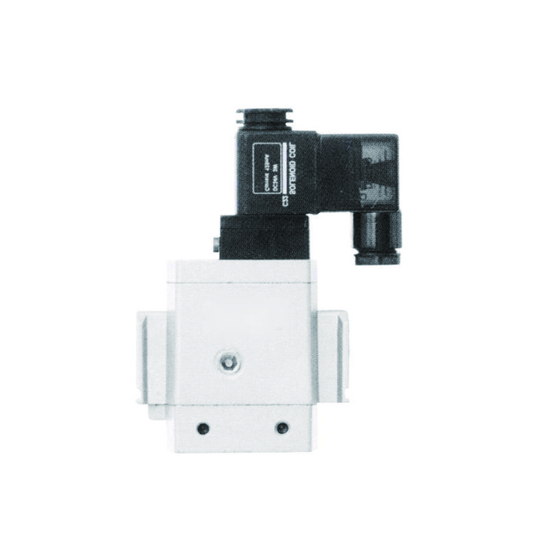
Are sudden valve closures causing destructive pressure spikes in your pneumatic systems? 💥 Air hammer creates violent pressure waves that can damage valves, burst pipes, and destroy expensive equipment, leading to catastrophic system failures and costly downtime.
Air hammer occurs when rapidly moving compressed air is suddenly stopped by valve closure, creating pressure waves that propagate through the system at sonic velocity1, potentially reaching pressures 5-10 times higher than normal operating pressure.
Last month, I received an urgent call from Robert, a maintenance engineer at a textile manufacturing plant in North Carolina. His facility was experiencing repeated valve failures and pipe ruptures due to uncontrolled air hammer effects, resulting in $30,000 weekly losses from production interruptions.
Tabla de conținut
- What Causes Air Hammer in Pneumatic Systems?
- How Do Pressure Waves Propagate Through Pneumatic Piping?
- What Are the Most Effective Methods to Prevent Air Hammer Damage?
- How Can You Calculate Air Hammer Pressure in Your System?
What Causes Air Hammer in Pneumatic Systems?
Understanding the root causes of air hammer is essential for preventing system damage and ensuring reliable operation. ⚡
Air hammer is caused by rapid valve closure, sudden flow direction changes, compressor shutdown, or emergency stops that create momentum transfer2 from moving air mass to stationary system components, generating destructive pressure waves.
Primary Trigger Mechanisms
Închiderea rapidă a supapei
The most common cause occurs when fast-acting valves close quickly:
- Electrovalve Solenoid: Close in 10-50 milliseconds
- Supape cu bilă: Quarter-turn closure creates instant stoppage
- Emergency Shutoffs: Designed for rapid closure but create maximum hammer effect
- Supape de reținere: Slam shut when flow reverses
Flow Velocity Impact
Higher air velocities increase hammer severity:
| Air Velocity (m/s) | Hammer Risk Level | Aplicații tipice |
|---|---|---|
| 5-10 | Scăzut | Unelte pneumatice standard |
| 10-20 | Moderat | Automatizare industrială |
| 20-30 | Înaltă | Ambalare de mare viteză |
| 30+ | Severe | Emergency blow-off systems |
System Configuration Factors
Pipe Length and Diameter
Longer pipes with smaller diameters amplify pressure waves:
Critical Parameters:
- Lungime: Longer runs increase wave reflection time
- Diametru: Smaller pipes concentrate pressure effects
- Grosimea peretelui: Thin walls cannot withstand pressure spikes
- Material: Steel pipes handle pressure better than plastic
Bepto Solution Approach
Our rodless cylinder systems incorporate advanced flow control technology and gradual valve closure mechanisms that reduce air hammer effects by 70-80% compared to standard pneumatic components. We design our systems with proper sizing and flow management to prevent destructive pressure waves.
How Do Pressure Waves Propagate Through Pneumatic Piping?
Pressure wave behavior follows specific physical laws that determine system impact severity. 🌊
Pressure waves travel through pneumatic systems at sonic velocity (approximately 343 m/s in air), reflecting off closed ends and pipe fittings, creating standing wave patterns3 that can amplify pressure to dangerous levels.

Wave Propagation Physics
Sonic Velocity Calculations
Air hammer waves travel at the speed of sound in the medium:
Formula: c = √(γ × R × T)
Unde:
- c = Wave velocity (m/s)
- γ = Specific heat ratio4 (1.4 for air)
- R = Gas constant (287 J/kg·K for air)
- T = Absolute temperature (K)
Pressure Wave Amplitude
The Joukowsky equation5 determines maximum pressure rise:
ΔP = ρ × c × Δv
Unde:
- ΔP = Pressure increase (Pa)
- ρ = Air density (kg/m³)
- c = Wave velocity (m/s)
- Δv = Velocity change (m/s)
Wave Reflection and Amplification
Boundary Conditions
Different pipe endings create various reflection patterns:
Reflection Types:
- Closed End: 100% pressure reflection, zero velocity
- Open End: 100% velocity reflection, zero pressure
- Partial Restriction: Mixed reflection creating complex patterns
- Cameră de expansiune: Pressure reduction through volume increase
Studiu de caz din lumea reală
Consider Sarah, a process engineer at a food packaging facility in Wisconsin. Her high-speed pneumatic actuators were experiencing premature failures due to pressure spikes reaching 15 bar in a 6-bar system. The waves were reflecting off dead-end branches and amplifying at specific frequencies. By implementing our Bepto flow control valves with gradual closure profiles and installing properly sized accumulators, we reduced peak pressures to 7.5 bar and eliminated equipment failures. 🎯
What Are the Most Effective Methods to Prevent Air Hammer Damage?
Multiple engineering solutions can effectively control and eliminate air hammer effects. 🛡️
Effective air hammer prevention includes gradual valve closure, pressure accumulators, surge suppressors, proper pipe sizing, flow restrictors, and system design modifications that absorb energy and reduce pressure wave amplitude.
Engineering Control Methods
Gradual Valve Closure
Implementing controlled closure rates prevents sudden momentum changes:
Closure Time Guidelines:
- Aplicații standard: 0.5-2 seconds closure time
- High-Pressure Systems: 2-5 seconds for safety
- Large Diameter Pipes: Proportionally longer closure times
- Critical Systems: Programmable closure profiles
Pressure Accumulator Installation
Accumulators absorb pressure spikes and provide energy storage:
| Tip acumulator | Intervalul de presiune | Timp de răspuns | Aplicații |
|---|---|---|---|
| Bladder Type | 1-300 bar | <10 ms | Destinație generală |
| Piston Type | 1-400 bar | 10-50 ms | Destinație grea |
| Diaphragm Type | 1-200 bar | <5 ms | Clean air systems |
| Metal Bellows | 1-100 bar | <20 ms | Temperatură ridicată |
System Design Solutions
Optimizarea dimensionării conductelor
Proper pipe sizing reduces flow velocities and hammer potential:
Design Criteria:
- Velocity Limits: Keep air velocity below 15 m/s
- Cădere de presiune: Maximum 0.1 bar per 100m of pipe
- Diameter Selection: Use larger diameters for high-flow applications
- Grosimea peretelui: Design for 150% of maximum expected pressure
Bepto Prevention Technology
Our pneumatic systems incorporate multiple air hammer prevention features including soft-start valves, integrated accumulators, and intelligent closure control. We provide complete system analysis and custom solutions that eliminate hammer effects while maintaining performance.
How Can You Calculate Air Hammer Pressure in Your System?
Accurate pressure calculations help predict and prevent dangerous pressure spikes. 📊
Air hammer pressure calculation uses the Joukowsky equation ΔP = ρ × c × Δv, combined with system-specific factors including pipe geometry, valve closure time, and reflection coefficients to determine maximum expected pressure rise.
Calculation Methodology
Step-by-Step Process
Follow this systematic approach for accurate predictions:
- Determine Initial Conditions: Operating pressure, temperature, flow velocity
- Calculate Wave Speed: Use sonic velocity formula for air
- Apply Joukowsky Equation: Calculate initial pressure rise
- Account for Reflections: Consider pipe end conditions
- Apply Safety Factors: Multiply by 1.5-2.0 for design margins
Exemplu practic de calcul
For a typical industrial system:
Parametrii dați:
- Operating Pressure: 6 bar
- Air Temperature: 20°C (293K)
- Initial Velocity: 20 m/s
- Pipe Length: 50m
- Valve Closure Time: 0.1s
Calcule:
- Wave Speed: c = √(1.4 × 287 × 293) = 343 m/s
- Air Density: ρ = P/(R×T) = 7.14 kg/m³
- Pressure Rise: ΔP = 7.14 × 343 × 20 = 49,000 Pa (0.49 bar)
- Maximum Pressure: 6 + 0.49 = 6.49 bar
Advanced Analysis Methods
Computer Simulation
Modern CFD software provides detailed pressure wave analysis:
Software Capabilities:
- Transient Analysis: Time-dependent pressure mapping
- 3D Modeling: Complex geometry effects
- Multiple Reflections: Accurate wave interaction prediction
- Optimizarea sistemului: Design parameter sensitivity analysis
Choosing the right air hammer prevention strategy protects your pneumatic systems from destructive pressure waves and ensures reliable long-term operation.
FAQs About Air Hammer
What’s the difference between air hammer and water hammer in industrial systems?
Air hammer involves compressible gas creating pressure waves at sonic velocity, while water hammer uses incompressible liquid generating much higher pressure spikes at faster propagation speeds. Water hammer typically creates pressures 10-50 times higher than air hammer due to liquid incompressibility. However, air hammer affects larger system volumes and can cause sustained oscillations. Both phenomena follow similar physics but require different prevention strategies – air systems use accumulators and gradual closure, while liquid systems rely on surge tanks and check valves.
How quickly do air hammer pressure waves travel through pneumatic piping?
Air hammer pressure waves propagate at sonic velocity, approximately 343 m/s in standard air conditions, reaching system endpoints in milliseconds. Wave speed depends on air temperature and composition – higher temperatures increase velocity while moisture content slightly reduces it. In a typical 100-meter pneumatic line, pressure waves travel end-to-end in about 0.3 seconds, reflecting back and creating complex interference patterns. This rapid propagation means protective devices must respond within milliseconds to be effective.
Can air hammer damage rodless cylinders and pneumatic actuators?
Yes, air hammer can cause seal damage, rod bending, mounting stress, and premature wear in rodless cylinders by creating pressure spikes exceeding design limits. Our Bepto rodless cylinders incorporate internal dampening and pressure relief features that protect against hammer effects. Standard cylinders may experience 2-3x normal pressure during hammer events, potentially causing catastrophic failure. We design our systems with integrated protection including flow restrictors, soft-start valves, and pressure monitoring to prevent damage and extend service life.
What pipe materials best resist air hammer damage?
Steel and stainless steel pipes provide the best air hammer resistance due to high tensile strength and wall thickness, while plastic pipes are most vulnerable to pressure spike damage. Steel pipes can typically handle 3-5x normal pressure without failure, while PVC may crack at 2x normal pressure. Copper tubing offers moderate resistance but can work-harden under repeated pressure cycling. For critical applications, we recommend schedule 80 steel pipe with proper support brackets to handle both static and dynamic pressure loads.
How do you size accumulators for effective air hammer protection?
Accumulator volume should equal 10-20% of system air volume, with pre-charge pressure set at 60-80% of normal operating pressure for optimal hammer suppression. Larger accumulators provide better protection but increase system cost and complexity. Response time is critical – bladder accumulators respond fastest (<10ms) while piston types may take 50ms. Location matters too – install accumulators near potential hammer sources like fast-acting valves. Our engineering team provides detailed accumulator sizing calculations based on your specific system parameters and protection requirements.
-
Learn the definition of sonic velocity (the speed of sound) and how it’s calculated in a gas. ↩
-
Explore the physics principle of momentum transfer and how it applies to moving fluids. ↩
-
Understand the physics of standing waves and how they are formed by wave reflection. ↩
-
Read a technical definition of the specific heat ratio (gamma) and its role in thermodynamics. ↩
-
See the Joukowsky equation and learn how it’s used to calculate pressure surges in fluid systems. ↩


