

Are your pneumatic control systems experiencing timing inconsistencies, unexpected sequence failures, or dangerous interlock bypasses? These common problems often stem from improper logic component selection, leading to production inefficiencies, safety incidents, and increased maintenance costs. Selecting the right pneumatic logic components can immediately solve these critical issues.
The ideal pneumatic logic system must provide reliable sequential operation, precise timing control, and fail-safe interlock mechanisms. Proper component selection requires understanding sequential diagram standards, time delay validation methodologies, and multi-signal interlock testing procedures to ensure system integrity and performance.
I recently consulted with a packaging equipment manufacturer who was experiencing intermittent sequence failures in their case erector, resulting in a 7% production loss. After implementing properly specified pneumatic logic components with validated timing and interlocks, their failure rate dropped below 0.5%, saving over $180,000 annually in lost production. Let me share what I’ve learned about selecting the perfect pneumatic logic components for your application.
Table of Contents
- How to Create Standards-Compliant Pneumatic Sequential Diagrams
- Time Delay Module Accuracy Validation Methods for Precise Control
- Multi-Signal Interlock Mechanism Testing for Fail-Safe Operation
How to Create Standards-Compliant Pneumatic Sequential Diagrams
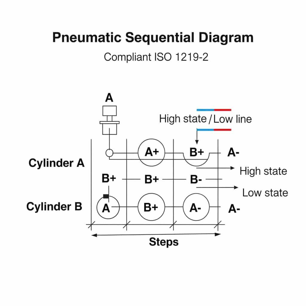
Sequential diagrams are the foundation of pneumatic logic system design, providing a standardized representation of system operation that ensures clarity and consistency.
Pneumatic sequential diagrams visualize the time-based relationships between system events using standardized symbols and formatting conventions defined by ISO 1219-21 and ANSI/JIC standards. Properly constructed diagrams enable accurate component selection, facilitate troubleshooting, and serve as essential documentation for system maintenance and modification.
Understanding Sequential Diagram Standards
Several international standards govern pneumatic sequential diagram creation:
| Standard | Focus | Key Elements | Application |
|---|---|---|---|
| ISO 1219-2 | Fluid power systems | Symbol standards, diagram layout | International standard |
| ANSI/JIC | Industrial control systems | American symbol conventions | US manufacturing |
| IEC 60848 | GRAFCET/SFC | Step-transition methodology | Complex sequences |
| VDI 3260 | Pneumatic logic | Specialized logic symbols | German/European systems |
Sequential Diagram Types and Applications
Different diagram types serve specific purposes in pneumatic logic system design:
Displacement-Step Diagram
The most common format for pneumatic sequence representation:
Structure
– Vertical axis: System components (cylinders, valves)
– Horizontal axis: Steps or time progression
– Movement lines: Component activation/deactivationKey features
– Clear visualization of component movement
– Step-by-step progression
– Identification of simultaneous actions
– Distinction between extending/retracting movementsBest applications
– Multi-cylinder sequences
– Troubleshooting existing systems
– Operator training materials
Signal-Step Diagram
Focuses on control signals rather than physical movements:
Structure
– Vertical axis: Signal sources (limit switches, sensors)
– Horizontal axis: Steps or time progression
– Signal lines: ON/OFF state changesKey features
– Emphasis on control logic
– Clear signal timing relationships
– Identification of signal overlaps
– Visualization of interlock conditionsBest applications
– Complex logic systems
– Signal-dependent sequences
– Interlock verification
Function Diagram (GRAFCET2/SFC)
Structured approach for complex sequences:
Structure
– Steps (rectangles): Stable system states
– Transitions (horizontal lines): Conditions for state change
– Directed links: Flow between steps
– Actions: Operations performed in each stepKey features
– Clear distinction between states and transitions
– Support for parallel sequences
– Conditional branching representation
– Hierarchical structure capabilityBest applications
– Complex, multi-path sequences
– Systems with conditional operations
– Integration with PLC programming
Standard Symbol Conventions
Consistent symbol usage is critical for diagram clarity:
Actuator Representation
| Component | Symbol Convention | Movement Representation | State Indication |
|---|---|---|---|
| Single-acting cylinder | Single line with return spring | Horizontal displacement | Extended/retracted position |
| Double-acting cylinder | Double line without spring | Horizontal displacement | Extended/retracted position |
| Rotary actuator | Circle with rotation arrow | Angular displacement | Rotated/home position |
| Gripper | Parallel lines with arrows | Open/close indication | Open/closed state |
Signal Element Representation
| Element | Symbol | State Representation | Connection Convention |
|---|---|---|---|
| Limit switch | Square with roller | Filled when activated | Dashed line to actuator |
| Pressure switch | Circle with diaphragm | Filled when activated | Solid line to pressure source |
| Timer | Clock face | Radial line movement | Connection to triggered element |
| Logic element | Function symbol (AND, OR) | Output state indication | Input/output lines |
Sequential Diagram Creation Process
Follow this systematic approach to create standards-compliant sequential diagrams:
System analysis
– Identify all actuators and their movements
– Define sequence requirements
– Determine control dependencies
– Identify timing requirementsComponent listing
– Create vertical axis component list
– Arrange in logical order (typically flow of operation)
– Include all actuators and signal elements
– Add timing/logic componentsStep definition
– Define distinct steps in sequence
– Identify step transition conditions
– Determine step durations (if applicable)
– Identify parallel operationsDiagram construction
– Draw component movement lines
– Add signal activation points
– Include timing elements
– Mark interlocks and dependenciesVerification and validation
– Check for logical consistency
– Verify against sequence requirements
– Validate timing relationships
– Confirm interlock functionality
Common Sequential Diagram Errors
Avoid these frequent mistakes in diagram creation:
Logical inconsistencies
– Signal dependencies without sources
– Impossible simultaneous movements
– Missing return movements
– Incomplete sequencesStandard violations
– Inconsistent symbol usage
– Non-standard line types
– Improper component representation
– Unclear step transitionsPractical issues
– Unrealistic timing requirements
– Insufficient sensor positioning
– Unaccounted mechanical constraints
– Missing safety considerations
Case Study: Sequential Diagram Optimization
I recently worked with a food processing equipment manufacturer who was experiencing intermittent jamming in their product handling system. The existing documentation was incomplete and inconsistent, making troubleshooting difficult.
Analysis revealed:
- Inconsistent sequential diagram formats across documentation
- Missing signal dependencies in critical transitions
- Unclear timing requirements between movements
- Undocumented manual interventions in the sequence
By implementing a comprehensive solution:
- Created standardized displacement-step diagrams for operator use
- Developed detailed signal-step diagrams for maintenance
- Implemented GRAFCET diagrams for complex decision points
- Standardized symbol usage across all documentation
The results were significant:
- Identified three previously undetected logic errors
- Discovered critical timing issue in product transfer
- Implemented proper interlocks at key sequence points
- Reduced jam incidents by 83%
- Decreased troubleshooting time by 67%
- Improved operator understanding of system operation
Time Delay Module Accuracy Validation Methods for Precise Control
Pneumatic time delay modules are critical components in sequential systems, but their performance must be validated to ensure reliable operation.
Time delay validation methodologies systematically verify the accuracy, repeatability, and stability of pneumatic timing modules under various operating conditions. Proper validation ensures that timing-critical operations maintain required precision throughout their service life, preventing sequence failures and production disruptions.
Understanding Pneumatic Time Delay Fundamentals
Before validation, it’s essential to understand the operating principles and specifications of pneumatic timing devices:
Types of Pneumatic Time Delay Modules
| Delay Type | Operating Principle | Typical Accuracy | Adjustment Range | Best Applications |
|---|---|---|---|---|
| Orifice-reservoir | Air flowing through restriction | ±10-15% | 0.1-30 seconds | General purpose |
| Precision orifice | Calibrated restriction with compensation | ±5-10% | 0.2-60 seconds | Industrial sequences |
| Mechanical timer | Clockwork or escapement mechanism | ±2-5% | 0.5-300 seconds | Critical timing |
| Pneumatic dashpot | Controlled air displacement | ±7-12% | 0.1-10 seconds | Cushioning, damping |
| Electronic-pneumatic | Electronic timer with pneumatic output | ±1-3% | 0.01-999 seconds | Precision applications |
Critical Performance Parameters
Key metrics that must be validated for any timing module:
Accuracy
– Deviation from set point under standard conditions
– Typically expressed as percentage of set timeRepeatability
– Variation between successive operations
– Critical for consistent sequence performanceTemperature stability
– Timing variation across operating temperature range
– Often overlooked but significant in real applicationsPressure sensitivity
– Timing variation with supply pressure changes
– Important for systems with fluctuating pressureLong-term drift
– Change in timing over extended operation
– Affects maintenance intervals and calibration needs
Standardized Validation Methodologies
Several established methods exist for validating time delay performance:
Basic Timing Validation Method (ISO 6358 Compatible)
Suitable for general industrial applications:
Test setup
– Install timing module in test circuit
– Connect precision pressure sensors at input and output
– Use high-speed data acquisition system (minimum 100Hz)
– Include precision supply pressure regulation
– Control ambient temperature to 23°C ±2°CTest procedure
– Set delay to target value
– Apply standard operating pressure (typically 6 bar)
– Trigger timing module
– Record pressure profiles at input and output
– Define timing point at 50% of pressure rise
– Repeat minimum 10 cycles
– Test at minimum, typical, and maximum delay settingsAnalysis metrics
– Calculate mean delay time
– Determine standard deviation
– Calculate accuracy (deviation from set point)
– Determine repeatability (maximum variation)
Comprehensive Validation Protocol
For critical applications requiring detailed performance data:
Standard condition baseline
– Perform basic validation at reference conditions
– Establish baseline performance metrics
– Minimum 30 cycles for statistical validityPressure sensitivity testing
– Test at -15%, nominal, and +15% supply pressure
– Calculate pressure coefficient (% change per bar)
– Identify minimum pressure for reliable operationTemperature sensitivity testing
– Test at minimum, nominal, and maximum operating temperatures
– Allow complete thermal stabilization (minimum 2 hours)
– Calculate temperature coefficient (% change per °C)Long-term stability testing
– Operate continuously for 10,000+ cycles
– Sample timing at regular intervals
– Calculate drift rate and projected calibration intervalLoad sensitivity testing
– Test with varying downstream volumes
– Test with different connected components
– Determine maximum reliable load capacity
Validation Equipment Requirements
Proper validation requires appropriate test equipment:
Essential Equipment Specifications
| Equipment | Minimum Specification | Recommended Specification | Purpose |
|---|---|---|---|
| Pressure sensors | 0.5% accuracy, 100Hz sampling | 0.1% accuracy, 1kHz sampling | Measure pressure profiles |
| Data acquisition | 12-bit resolution, 100Hz | 16-bit resolution, 1kHz | Record timing data |
| Timer/counter | 0.01s resolution | 0.001s resolution | Reference measurement |
| Pressure regulation | ±0.1 bar stability | ±0.05 bar stability | Control test conditions |
| Temperature control | ±2°C stability | ±1°C stability | Environmental control |
| Flow measurement | 2% accuracy | 1% accuracy | Verify flow characteristics |
Validation Data Analysis and Interpretation
Proper analysis of validation data is critical for meaningful results:
Statistical analysis
– Calculate mean, median, and standard deviation
– Determine Cpk3 and process capability
– Identify outliers and special causes
– Apply control chart methodologiesCorrelation analysis
– Relate timing variations to environmental factors
– Identify significant influencing variables
– Develop compensation strategiesFailure mode analysis
– Identify conditions causing timing failures
– Determine operational limits
– Establish safety margins
Case Study: Time Delay Validation Implementation
I recently worked with a pharmaceutical equipment manufacturer who was experiencing inconsistent dwell times in their vial filling system, resulting in fill volume variations.
Analysis revealed:
- Timing modules operating at ±12% accuracy (specification required ±5%)
- Significant temperature sensitivity during production shifts
- Repeatability issues after extended operation
- Pressure fluctuations affecting timing consistency
By implementing a comprehensive validation program:
- Developed custom validation protocol based on application requirements
- Tested all timing modules under actual operating conditions
- Characterized performance across pressure and temperature ranges
- Implemented statistical process control for timing validation
The results were significant:
- Identified three timing modules requiring replacement
- Discovered critical pressure regulation issue
- Implemented temperature compensation strategy
- Reduced timing variation from ±12% to ±3.5%
- Decreased fill volume variation by 68%
- Established 6-month validation interval based on drift analysis
Multi-Signal Interlock Mechanism Testing for Fail-Safe Operation
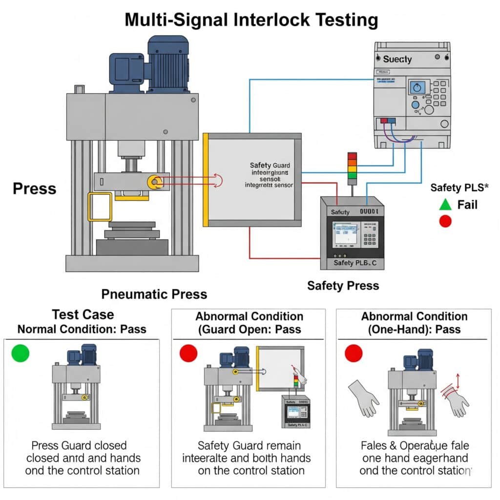
Interlock systems are critical safety elements in pneumatic logic systems, requiring thorough testing to ensure proper operation under all conditions.
Multi-signal interlock testing methodologies systematically verify that pneumatic safety systems prevent hazardous operations when protective conditions are not met. Comprehensive testing ensures that interlocks function correctly under normal, abnormal, and fault conditions, protecting personnel and equipment from potentially dangerous situations.
Understanding Pneumatic Interlock Fundamentals
Interlocks use logical combinations of signals to permit or prevent operations:
Types of Pneumatic Interlock Systems
| Interlock Type | Operating Principle | Safety Level | Complexity | Best Applications |
|---|---|---|---|---|
| Single-signal | Basic blocking function | Low | Simple | Non-critical operations |
| Dual-signal | Two-condition verification | Medium | Moderate | Standard safety applications |
| Voting logic | 2-out-of-3 or similar redundancy | High | Complex | Critical safety functions |
| Monitored interlock | Self-checking capability | Very high | Very complex | Personnel safety |
| Timed interlock | Sequence-dependent permissive | Medium | Moderate | Process sequencing |
Interlock Implementation Methods
Common approaches to implementing pneumatic interlocks:
Logic element approach
– Uses AND, OR, NOT functions
– Discrete component implementation
– Visible operation state
– Easily modifiedValve interlock approach
– Mechanical or pilot interlocking of valves
– Integrated into valve design
– Typically more robust
– Less flexible for modificationsMixed-technology approach
– Combines pneumatic with electrical/electronic elements
– Often uses pressure switches as interfaces
– Higher flexibility
– Requires multi-discipline expertise
Comprehensive Interlock Testing Methodology
A systematic approach to validating interlock functionality:
Functional Testing Protocol
Basic verification of intended operation:
Normal operation testing
– Verify interlock permits operation when all conditions met
– Confirm proper sequencing with timing requirements
– Test multiple cycles for consistency
– Verify proper reset behaviorBlocking function testing
– Test each interlock condition individually
– Verify operation is prevented when any condition is not met
– Confirm appropriate indication/feedback
– Test boundary conditions (just above/below thresholds)Reset behavior testing
– Verify proper reset after interlock activation
– Test automatic and manual reset functions
– Confirm no unexpected restoration of operation
– Verify memory functions if applicable
Fault Condition Testing
Verification of behavior under abnormal conditions:
Signal failure testing
– Simulate sensor/switch failures
– Test with disconnected signal lines
– Verify fail-safe behavior
– Confirm appropriate alarms/indicatorsPower loss testing
– Test behavior during pressure loss
– Verify state after pressure restoration
– Confirm no unexpected movement during recovery
– Test partial pressure scenariosComponent failure simulation
– Introduce leakage in critical components
– Test with partially functioning valves
– Simulate stuck components
– Verify system response to degraded conditions
Performance Boundary Testing
Verification of operation at specification limits:
Timing margin testing
– Test at minimum and maximum specified timing
– Verify operation with fastest possible signal changes
– Test with slowest expected signal changes
– Confirm margin between normal and fault timingPressure boundary testing
– Test at minimum specified pressure
– Test at maximum specified pressure
– Verify operation during pressure fluctuations
– Determine pressure sensitivity of interlock functionEnvironmental condition testing
– Test at temperature extremes
– Verify operation with vibration/shock
– Test with contamination introduction
– Confirm function in worst-case environmental conditions
Interlock Test Documentation Requirements
Proper documentation is essential for interlock testing:
Critical Documentation Elements
Test specification
– Clear pass/fail criteria
– Reference to applicable standards
– Required test conditions
– Test equipment specificationsTest procedure
– Step-by-step test instructions
– Initial conditions and setup
– Specific measurements required
– Safety precautions during testingTest results
– Raw data from testing
– Analysis and calculations
– Pass/fail determination
– Anomalies and observationsVerification documentation
– Tester identification and qualifications
– Test equipment calibration records
– Verification of test conditions
– Approval signatures
Interlock Testing Standards and Regulations
Several standards govern interlock testing requirements:
| Standard/Regulation | Focus | Key Requirements | Application |
|---|---|---|---|
| ISO 138494 | Safety of machinery | Performance level verification | Machinery safety |
| IEC 61508 | Functional safety | SIL level validation | Process safety |
| OSHA 1910.1475 | Lockout/tagout | Verification of isolation | Worker safety |
| EN 983 | Pneumatic safety | Specific pneumatic requirements | European machinery |
| ANSI/PMMI B155.1 | Packaging machinery | Industry-specific requirements | Packaging equipment |
Case Study: Interlock System Optimization
I recently consulted with an automotive parts manufacturer who experienced a safety incident when a pneumatic press operated unexpectedly during maintenance.
Analysis revealed:
- Inadequate interlock testing program
- Single-point failures in critical safety circuits
- No formal validation after system modifications
- Inconsistent testing methodology between shifts
By implementing a comprehensive solution:
- Developed standardized interlock testing protocols
- Implemented fault injection testing for all safety circuits
- Created detailed test documentation and records
- Established regular validation schedule
- Trained maintenance personnel on testing procedures
The results were significant:
- Identified seven previously undetected failure modes
- Discovered critical interlock timing issue
- Implemented redundant interlocking for personnel safety
- Eliminated single-point failures in all safety circuits
- Achieved compliance with ISO 13849 Performance Level d
- Zero safety incidents in 18 months following implementation
Comprehensive Pneumatic Logic Component Selection Strategy
To select the optimal pneumatic logic components for any application, follow this integrated approach:
Define system requirements
– Determine sequence complexity and timing needs
– Identify safety-critical functions
– Establish environmental operating conditions
– Define reliability and maintenance requirementsDocument system logic
– Create standards-compliant sequential diagrams
– Identify all timing-dependent functions
– Map all required interlocks
– Document signal relationshipsSelect appropriate components
– Choose logic elements based on function requirements
– Select timing modules based on accuracy needs
– Determine interlock implementation approach
– Consider environmental compatibilityValidate system performance
– Test timing module accuracy and stability
– Verify interlock functionality under all conditions
– Confirm sequence operation matches diagrams
– Document all validation results
Integrated Selection Matrix
| Application Requirements | Recommended Logic Type | Timing Module Selection | Interlock Implementation |
|---|---|---|---|
| Simple sequence, non-critical | Basic valve logic | Standard orifice-reservoir | Single-signal interlock |
| Medium complexity, industrial | Dedicated logic elements | Precision orifice with compensation | Dual-signal interlock |
| Complex sequence, critical timing | Specialized logic modules | Electronic-pneumatic hybrid | Voting logic with monitoring |
| Safety-critical application | Redundant logic systems | Mechanical timer with monitoring | Monitored interlock with feedback |
| Harsh environment, reliable operation | Sealed logic modules | Temperature-compensated timer | Mechanically linked interlock |
Conclusion
Selecting the optimal pneumatic logic components requires understanding sequential diagram standards, time delay validation methodologies, and interlock testing procedures. By applying these principles, you can achieve reliable sequence operation, precise timing control, and fail-safe interlocking in any pneumatic control application.
FAQs About Pneumatic Logic Component Selection
How do I determine the required timing accuracy for my pneumatic system?
Analyze your process requirements by identifying timing-critical operations and their impact on product quality or system performance. For general material handling, ±10% accuracy is typically sufficient. For synchronized operations (like transfer points), aim for ±5% accuracy. For precision processes affecting product quality (filling, dispensing), you’ll need ±2-3% accuracy. Critical applications may require ±1% or better, usually achieved with electronic-pneumatic hybrid timers. Always add a safety margin of at least 25% to your calculated requirements, and validate timing under actual operating conditions rather than just bench testing.
What is the most reliable method for implementing critical safety interlocks?
For critical safety applications, implement redundant voting logic (2-out-of-3) with monitoring. Use mechanically linked valve elements where possible to prevent common-mode failures. Incorporate both positive and negative logic (verification of both presence AND absence of signals) for critical functions. Ensure the system defaults to a safe state under all failure conditions including power/pressure loss. Include visual indicators showing interlock status, and implement regular functional testing at intervals determined by risk assessment. For highest reliability, consider pneumatic-only solutions for areas where electrical systems might be compromised by environmental factors.
How often should pneumatic sequential diagrams be updated during system modifications?
Update pneumatic sequential diagrams before implementing any system modifications, not after. Treat the diagram as the master document that drives changes rather than a record of changes. After implementation, verify the actual system operation against the updated diagram and correct any discrepancies immediately. For minor modifications, update the affected portion of the diagram and review adjacent sequences for impact. For major modifications, perform a complete diagram review and validation. Maintain version control on all diagrams, and ensure all outdated versions are removed from service areas. Implement a formal review process requiring sign-off on diagram accuracy after each modification cycle.
-
Provides an overview of the ISO 1219-2 standard, which specifies the rules for drawing circuit diagrams for fluid power systems, including symbol usage and layout conventions. ↩
-
Explains the principles of GRAFCET (Sequential Function Chart), a standardized graphical language used for describing the behavior of sequential control systems, particularly in automation. ↩
-
Offers a detailed definition of the Process Capability Index (Cpk), a statistical tool used to measure the ability of a process to produce output within customer specification limits. ↩
-
Describes the ISO 13849 standard, which provides safety requirements and guidance on the principles for the design and integration of safety-related parts of control systems, including the determination of Performance Levels (PL). ↩
-
Provides information on the OSHA 1910.147 standard, also known as Lockout/Tagout (LOTO), which outlines the requirements for disabling machinery or equipment to prevent the release of hazardous energy during service or maintenance. ↩
