

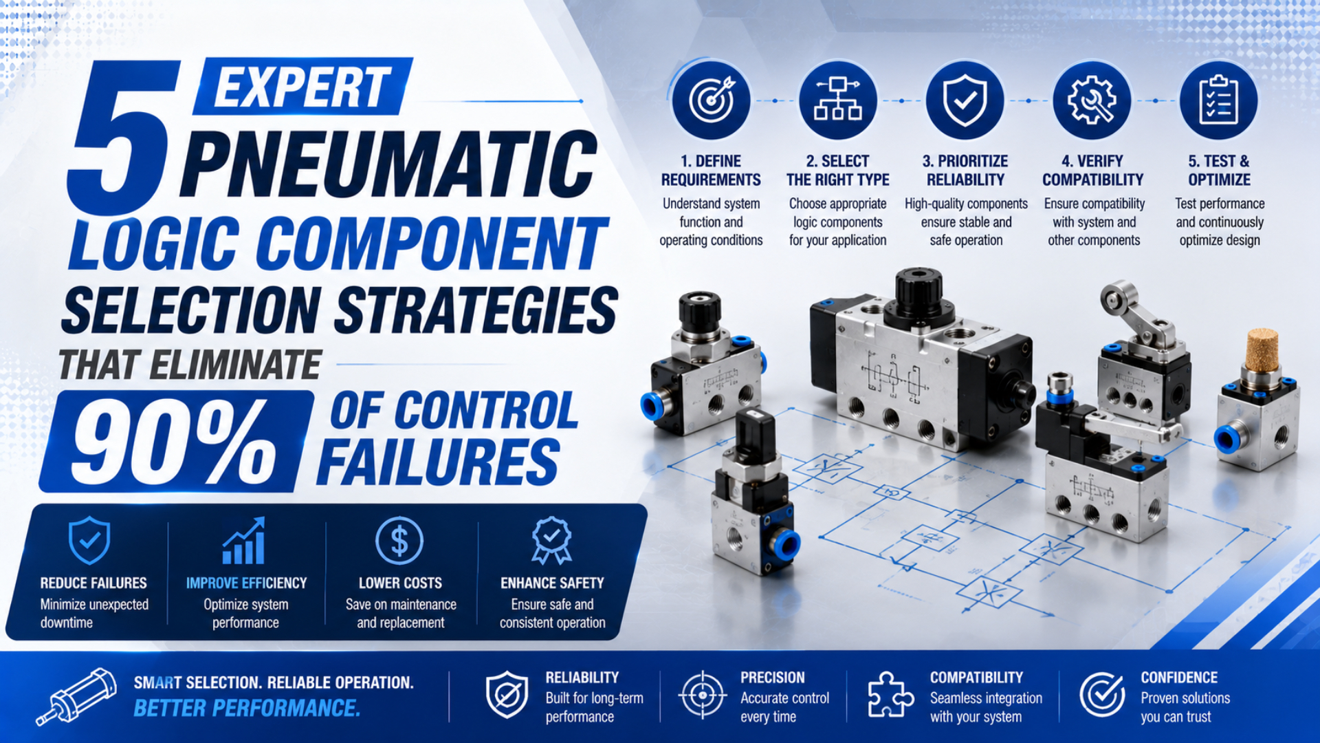
No published standard or manufacturer data supports a universal claim that five component-selection strategies will eliminate 90% of pneumatic control failures. The percentage remains in this article’s original title, but it is not a performance guarantee. The defensible goal is to remove five common selection errors before hardware is ordered: undefined states, an incompatible operating envelope, unsuitable timing, ambiguous reset behavior, and misuse of ordinary logic in a safety function.
Pneumatic logic is often treated as a collection of AND, OR, NOT, memory, and delay symbols. Real circuits fail at the interfaces between those symbols. A shuttle valve can pass the correct logical signal but respond differently as circuit volume and restriction change. A timer can meet its catalogue delay range yet produce an unacceptable machine sequence. A circuit can function perfectly in production and still be unsuitable for safeguarding personnel.
This guide turns those problems into a practical component-selection method. It applies to pneumatic sequence control, interlocks, signal conditioning, and simple machine automation. Safety-related control requires a separate risk-assessment and validation process.
Key Takeaways
- Begin with a state table or GRAFCET sequence, not a preferred valve part number.
- Check minimum pilot pressure, allowable pressure, flow, leakage, temperature, tubing, and downstream volume as one operating envelope.
- Use event confirmation for process-dependent motion; use timers only where elapsed time is the intended condition.
- Specify the circuit’s state after reset, pressure loss, pressure restoration, and manual override.
- Treat ordinary pneumatic logic and safety-related control as different engineering domains.
1. What State Table Must the Circuit Satisfy?
ISO 1219-2 provides rules for drawing hydraulic and pneumatic circuit diagrams, while IEC 60848 defines the GRAFCET language for sequential-function specifications. Together, they support a disciplined first step: describe permitted states, transitions, and outputs before selecting physical components (ISO 1219-2; IEC 60848).
Write one row for every meaningful machine state. For each row, record:
- the input conditions that must be true;
- the outputs that may be energized;
- the transition that ends the state;
- the response to conflicting or missing inputs;
- the required reset condition; and
- the state that must follow a loss and restoration of air pressure.
This exposes whether the circuit needs simple signal combination or stored state. A two-pressure valve can implement an AND condition, while a shuttle valve can implement an OR condition. Neither inherently remembers a completed step. If an output must remain active after the initiating signal disappears, the requirement is memory, not merely another logic gate.
Consider a transfer cylinder that may extend only when a part is present and a guard condition is satisfied. The required expression is:
That expression still does not define the whole sequence. The designer must state what happens if the part signal drops during extension, whether completion is confirmed by an end-position signal, and which signal resets the command. Those decisions determine whether a two-pressure valve, a bistable directional valve, or a more structured cascade circuit is appropriate.
Conflicting signals deserve their own state-table row. If extend and retract pilots can become active together, do not assume that the valve will select the preferred command. The outcome may depend on spool design, pilot area, pressure, and signal timing. Eliminate the conflict in the logic or define a priority architecture. See how to prevent opposing signals in a pneumatic logic circuit for the detailed failure modes.
Component-selection output
Convert the state table into a short functional specification. Name the required logic function, normal and abnormal input combinations, expected output state, reset rule, and acceptable transition behavior. Suppliers can then evaluate equivalent components against the same duty instead of interpreting a loosely annotated schematic.
2. Can the Logic Element Operate at the Real Pressure and Flow?
The SMC VR12 shuttle-valve manual lists a 0.05 MPa minimum operating pressure, 1.0 MPa maximum pressure, and a temperature range of -5 to 60°C. It also states that response time depends on the overall circuit design. These are model-specific limits, but they demonstrate why a logic symbol alone is not a specification (SMC VR12 manual).
Check the component at the least favorable point in the machine cycle, not only at the compressor or regulator gauge. A pilot signal that is adequate while the machine is idle may fall below the switching threshold when several actuators demand air simultaneously. Long small-bore tubes, silencers, speed controls, manifolds, and exhaust restrictions can delay pressure rise or slow signal decay.
The selection envelope should include:
| Requirement | What to document | Why it matters |
|---|---|---|
| Supply and signal pressure | Minimum dynamic pressure and maximum credible pressure | Determines whether the element will switch and remain within its rating |
| Flow path | Required signal or actuator flow at the relevant pressure ratio | Prevents a correct logic state from becoming a slow transition |
| Internal leakage | Permitted steady leakage and downstream volume | Leakage can charge a pilot volume or prevent a signal from venting |
| Tubing and fittings | Actual inside diameter, length, fitting restrictions, and exhaust path | These change fill and vent time |
| Temperature and media | Ambient range, compressed-air quality, and material compatibility | Affects seals, lubrication, leakage, and service life |
| Port and mounting arrangement | Thread, tube size, orientation, and service access | Avoids adapters and inaccessible manual overrides |
Do not transfer catalogue values between product families. For example, the VR12 range is sold as a compact shuttle valve, but its manual warns that backflow can occur and the output state during energy loss is not defined. The same document says that, when the unit is used for an interlock, the user should provide multiple interlocks and periodic verification. Those cautions belong in the design review, not in a maintenance footnote.
Flow capacity is especially important when a logic element directly pilots a large directional valve or supplies a pneumatic volume. A component may generate the intended binary state but take too long to charge the receiving line. If the logic path also drives an actuator, perform a pressure-loss and filling-time calculation for the complete path. A catalogue’s nominal flow value is not a universal machine response time.
Verify the worst dynamic condition
Instrument the signal at the receiving pilot port. Record pressure versus time during cold start, normal production, simultaneous demand, and exhaust. The useful result is not merely “the valve changed state.” It is the minimum pressure margin, switching delay, and venting behavior under the machine’s actual load cases.
For a modular architecture, keep logic flow separate from high actuator flow where practical. A logic stage can command a properly sized directional valve instead of becoming the actuator’s main restriction. The broader design approach is covered in building a reliable pneumatic circuit with modular valves.
3. Should the Sequence Use an Event or a Timer?
Festo’s VZ-3-PK-3 delay valve has an adjustable range of 0.25 to 5 seconds and a stated repetition accuracy of ±0.5 seconds. A different Festo supplementary time-delay family offers adjustment up to 30 seconds. The contrast shows why “pneumatic timer” is not a complete requirement (Festo VZ-3-PK-3; Festo time-delay valves).
Use an event-driven transition when the next step depends on the process reaching a physical condition. Typical events include:
- a cylinder reaching a confirmed end position;
- a clamp reaching verified pressure;
- a vacuum switch confirming part acquisition;
- a part sensor confirming transfer; or
- a pressure switch confirming that stored energy has been discharged.
Use a timer when elapsed time is itself the intended condition, or when a bounded delay is an explicitly accepted part of the process. Examples include a blow-off pulse, a dwell after a verified clamp event, or a delay that prevents two commands from overlapping. A timer should not impersonate a missing completion sensor where incomplete motion can damage the machine or create a hazard.
The timer’s catalogue range is only the first screen. Record the supply-pressure range, control-volume adjustment, reset time, repetition accuracy, environmental limits, switching threshold, and output flow. Then include downstream pilot volume and restriction. A timer can switch internally while the commanded valve changes later because its pilot line fills slowly.
For a sequence with variable actuator travel time, event confirmation usually preserves causality:
A time-driven transition instead assumes that completion occurs before a chosen delay:
The second expression does not prove that the cylinder moved, a part arrived, or pressure was achieved. It proves only that time elapsed. That distinction should appear in the state table and the failure analysis.
Validate a timer as part of the circuit
Test the complete signal path at minimum and maximum specified supply pressure and across the machine’s environmental range. Include the fastest and slowest credible actuator cycles, maximum downstream pilot volume, and a restart after pressure loss. Record the distribution of actual transition times rather than checking a single cycle.
If the sequence contains several cylinders, a cascade arrangement can prevent signal overlap and organize state progression without assuming identical motion time. See the guide to cascade circuit design using pneumatic valves and the worked discussion of sequential cylinder operation.
4. Memory, Reset, and Energy-Restoration Behavior
OSHA 1910.147 explicitly includes pneumatic energy and requires stored or residual energy to be relieved, disconnected, restrained, or otherwise rendered safe during servicing. ISO 4414 likewise provides general rules for pneumatic-system safety. Component selection must therefore define more than the energized production state (OSHA 1910.147; ISO 4414).
A monostable valve returns to a defined spring position when its pilot signal is removed. A bistable valve can retain its last commanded state until the opposite pilot arrives. Neither behavior is inherently better. The correct choice depends on what the machine must do after a signal disappears, air pressure decays, or energy returns.
For each memory element or bistable directional valve, answer these questions:
- Which signal sets the stored state?
- Which signal resets it?
- What happens if set and reset arrive together?
- Does pressure loss preserve, erase, or unpredictably alter the effective state?
- Can trapped downstream pressure keep an output active?
- What state follows gradual repressurization?
- Can a manual override create a state that the control logic does not recognize?
- Must an operator perform a deliberate reset before automatic motion resumes?
Pressure restoration deserves a dedicated test. A pneumatic memory circuit may appear to “remember” a state because trapped pressure remains in one pilot line, yet behave differently after a long shutdown or leakage. Conversely, a mechanically detented valve may retain spool position even though the control system has lost all knowledge of the previous process state.
Design vent paths as deliberately as supply paths. A signal that charges quickly but exhausts slowly can overlap the next command. A pilot-operated check valve can trap actuator pressure for load holding, but it also creates stored energy that must be considered during service and restart. Separate the production requirement for position or load retention from the hazardous-energy-control procedure.
Define reset as a machine state
“Reset” should not simply energize all valves to their nominal starting positions. It should verify the conditions required for a controlled restart: guards and process permissions, known actuator positions, acceptable pressure, cleared conflicting signals, and no retained command that can initiate unexpected motion.
A latching circuit can be useful when a command must persist, but it needs explicit reset dominance and restart behavior. The detailed logic is explained in building a pneumatic latching circuit with logic valves.
5. Is This Ordinary Control or a Safety Function?
ISO 13849-1:2023 provides a methodology for designing and integrating safety-related parts of control systems across pneumatic, hydraulic, mechanical, and electrical technologies. It does not prescribe the safety function or its required Performance Level. Those decisions must come from the machine risk assessment, such as the process defined by ISO 12100 (ISO 13849-1; ISO 12100).
Ordinary control logic is intended to make the machine perform its process. Safety-related control reduces risk when a defined hazardous event occurs. The same physical input may participate in both, but the safety function needs its own architecture, diagnostic coverage, reliability data, fault analysis, and validation.
The SMC VR12 manual makes this boundary concrete. It says the component cannot be used as an emergency shut-off valve and warns that energy-loss state and backflow require consideration. A general-purpose shuttle valve can be appropriate for a production OR function without being a validated safety component.
Do not assign a Performance Level from habit or copy an architecture from another machine. Define the hazardous event, required safe state, response time, demand characteristics, foreseeable faults, and reset behavior. Then determine the required risk reduction and select components with the necessary safety-related data.
Two-hand control illustrates the point. ISO 13851 defines three types of two-hand control device and says selection depends on the risk assessment. It also notes that a two-hand device protects only the person using it. A pair of ordinary pneumatic pushbuttons and an AND valve is not automatically a compliant safeguarding system (ISO 13851).
Safety-function review questions
- What hazard is reduced, and what is the required safe state?
- Which inputs initiate the safety response?
- What maximum response time is allowed?
- What happens after loss and restoration of each energy source?
- Which single faults must be detected or tolerated?
- Is component reliability and diagnostic data available for the calculation?
- Does reset prevent unexpected restart?
- Who will validate the completed safety function and record the evidence?
For the engineering framework, read how ISO 13849 safety circuits protect pneumatic systems. For the limitations and required behavior of a specific safeguarding concept, see the engineering of a two-hand safety control circuit.
Pneumatic Logic Component Selection FAQs
These questions address the selection errors that most often survive a schematic review. The answers deliberately distinguish model-specific catalogue data from system behavior, because ISO 1219-2 defines diagram rules while the completed circuit still needs duty-specific engineering and validation (ISO 1219-2).
What information should I send to a pneumatic logic valve supplier?
Send the state table or sequence, function required, minimum dynamic and maximum pressure, expected flow, tubing size and length, temperature, air quality, reset behavior, mounting constraints, and validation conditions. Include abnormal input combinations. A symbol and port size alone do not define the application’s switching or restart requirements.
When should I use a shuttle valve instead of a two-pressure valve?
Use a shuttle valve when either valid input may create the output, which is an OR function. Use a two-pressure valve when both inputs must be present, which is an AND function. Confirm pressure thresholds, backflow behavior, output flow, and conflicting-input behavior for the exact model and circuit.
Can a pneumatic timer confirm that a cylinder completed its stroke?
No. A timer confirms only that its set interval elapsed. Cylinder completion should be confirmed with an appropriate position, pressure, or process sensor when completion matters. Supply pressure, restriction, load, friction, and downstream pilot volume can all change the relationship between elapsed time and actual actuator position.
Does a bistable valve always retain a safe state after pressure loss?
No. A bistable valve may retain spool position, but the actuator state also depends on leakage, trapped pressure, external load, and repressurization behavior. “Last state” is not synonymous with “safe state.” Define the required condition through risk assessment, then test pressure loss and restoration explicitly.
Can standard pneumatic logic valves be used in an emergency-stop circuit?
Not by assumption. A safety function requires a defined architecture, reliability data, fault response, and validation consistent with its required risk reduction. Some general-purpose devices expressly prohibit emergency shut-off use. Select safety-related components and architecture only after the machine risk assessment defines the required function and Performance Level.
References
- ISO 1219-2:2012, Fluid power systems and components, graphical symbols and circuit diagrams
- IEC 60848:2013, GRAFCET specification language for sequential function charts
- ISO 4414:2010, Pneumatic fluid power, general rules and safety requirements
- ISO 12100:2010, Safety of machinery, risk assessment and risk reduction
- ISO 13849-1:2023, Safety-related parts of control systems
- ISO 13851:2019, Two-hand control devices
- OSHA 29 CFR 1910.147, The control of hazardous energy
- SMC VR12 shuttle valve installation and maintenance manual
- Festo VZ-3-PK-3 time delay valve
- Festo supplementary time delay valves