

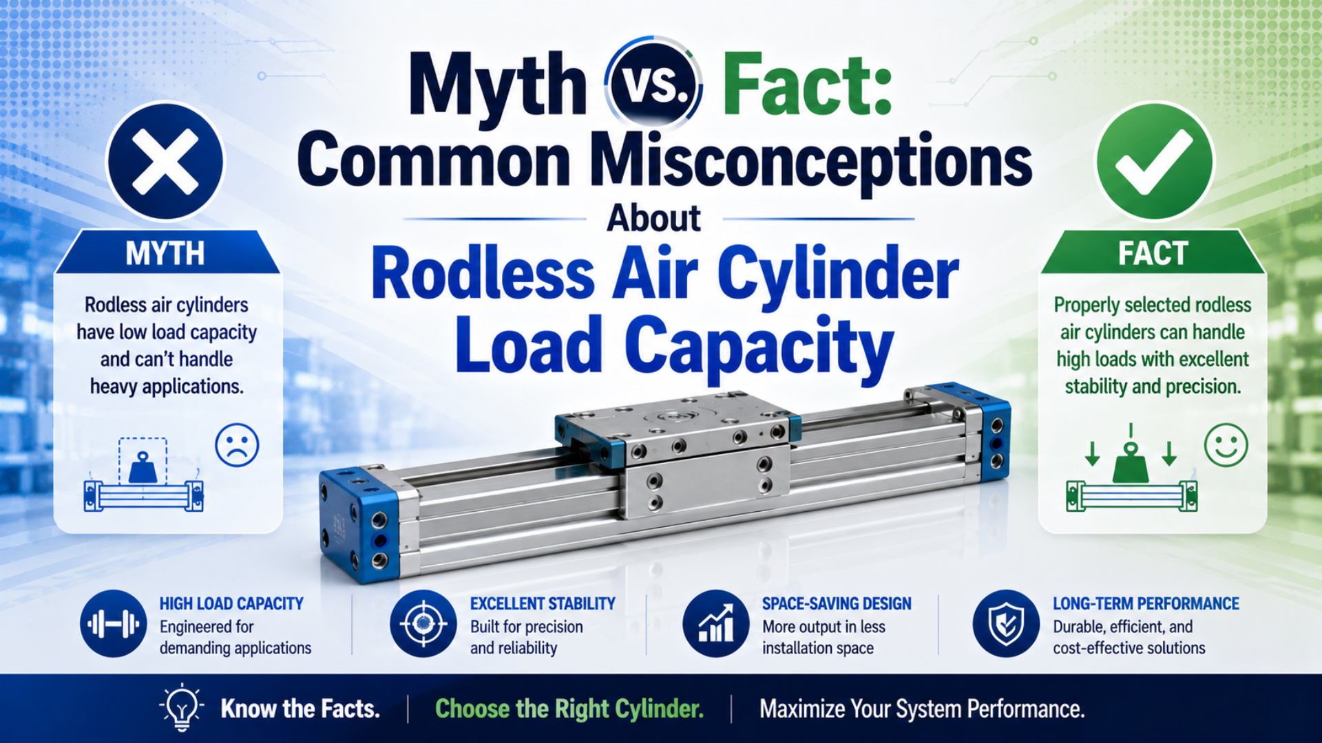
Rodless air cylinder load capacity is not a single payload number. It is the result of thrust, guide moment, carriage support, coupling style, stroke length, speed, end-stop energy, and pressure at the actuator during motion. A rodless cylinder can carry serious loads, but only when the load path is checked before the bore is chosen.
That is the practical answer. The myth is not just “rodless cylinders are weak.” The bigger myth is that a catalog thrust number proves the machine will survive. It does not.
Key Takeaways
- SMC lists MY1 mechanically jointed rodless cylinders from 10 mm to 100 mm bore and 0.1-0.8 MPa operating pressure.
- Rodless designs remove the external piston rod buckling problem, but guide moment and stopper impact still limit usable load.
- Check force, moment, pressure during motion, speed, cushioning, and RFQ geometry before trusting any load claim.
Rodless air cylinder load capacity is the usable load a rodless pneumatic axis can move after thrust, guidance, moment, speed, stops, mounting, and air supply are checked together. Guide moment is the pitch, roll, or yaw load created when the payload sits away from the carriage centerline. Catalog thrust is only the pressure-area force, before the real machine takes its share.
For suspended loads, vertical axes, guarded machinery, or unclear center-of-gravity data, prepare a drawing and load sketch before ordering.
In our experience, the first bad load-capacity decision is usually not a wrong bore. It is a missing sketch. If nobody marks the payload center of gravity, the bracket offset, and the end-stop position, the guide calculation starts as guesswork.
Short Answer: Rodless Load Capacity Is a Load-Path Check
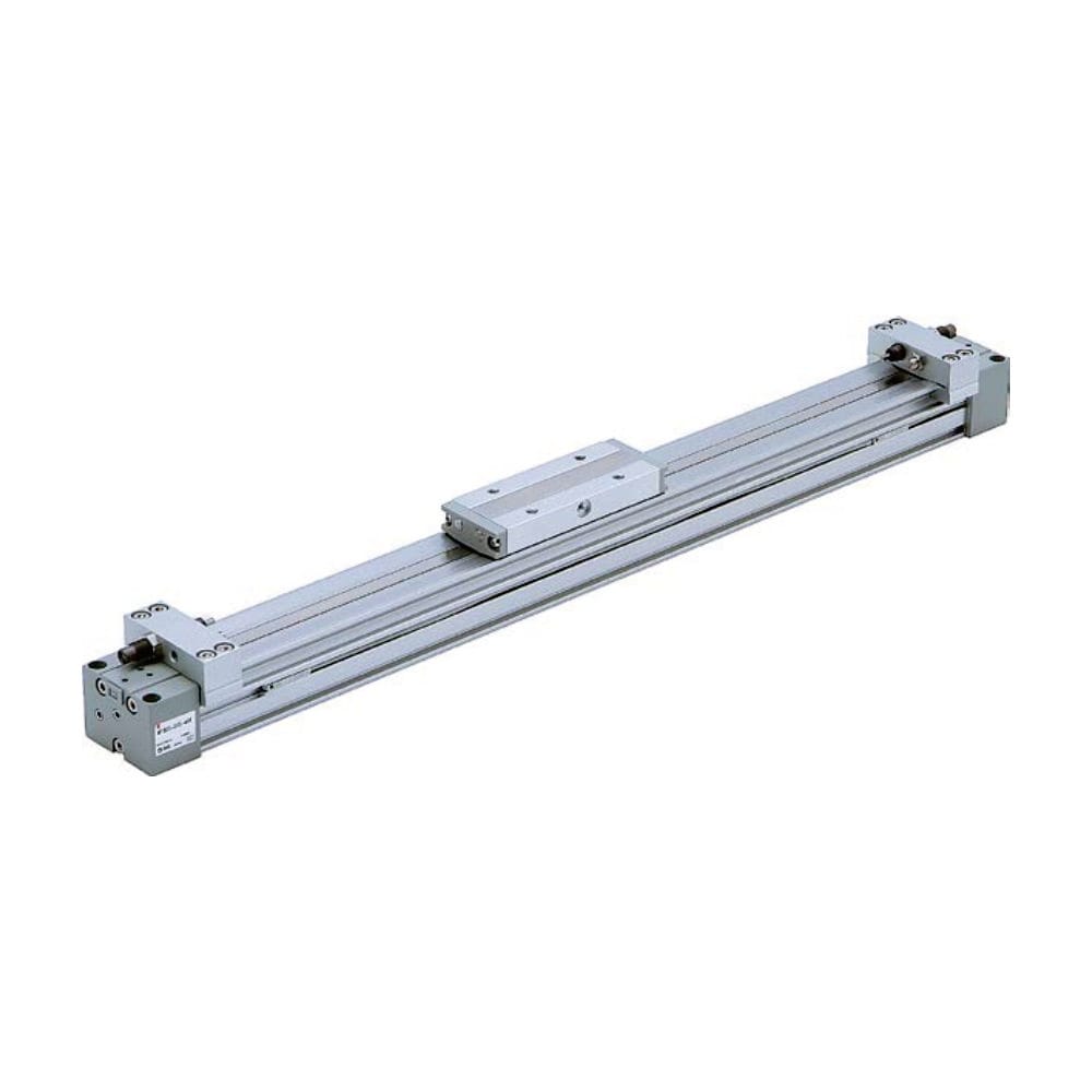
SMC’s MY1 catalog identifies the product family as mechanically jointed rodless cylinders, with bore sizes from 10 mm to 100 mm and a basic operating pressure range of 0.1-0.8 MPa (SMC MY1 catalog, 2015, retrieved 2026-07-08). Those numbers start the review; they do not finish it.
Use this hierarchy:
- Does the cylinder have enough theoretical thrust at the lowest measured working pressure?
- Does the carriage or external guide handle pitch, roll, and yaw moment?
- Does the stroke length need side support or a different actuator family?
- Can the axis stop the moving load without hammering the end caps or guide?
- Can the valve, tubing, and exhaust path hold pressure and speed during motion?
For the broader type split, read the guide to rodless pneumatic cylinder types. This article stays on one buyer question: whether the load-capacity assumption is true.
Myth 1: A Rodless Air Cylinder Is Always Light Duty
SMC’s MY1 series includes 5 guide families, from basic type through high-rigidity linear guide type, and its high-rigidity MY1HT 50/63 feature page states a maximum load mass of 320 kg for that example family (SMC MY1 catalog, 2015, retrieved 2026-07-08). The fact is series-specific: some rodless cylinders are light, and some are built for heavier guided work.
The safer statement is this: a rodless cylinder is not automatically weak, and it is not automatically heavy-duty. The answer depends on the exact series, guide style, stroke, mounting, load offset, speed, stopper arrangement, and available air pressure.
Do not copy generic “pounds of load” tables unless they come from the exact model and operating condition. A 63 mm bore in one product family is not the same design as a 63 mm bore in another product family. The carriage and guide can be the real limit.
| Myth wording | Better engineering wording |
|---|---|
| Rodless cylinders are only for light loads | Some rodless families are light-duty; guided and high-rigidity families can carry higher loads when their moment limits are respected |
| Bigger bore always means bigger payload | Bigger bore increases thrust, but the guide can still be overloaded |
| Load capacity is a single catalog number | Load capacity depends on mass, offset, speed, support, stops, and air pressure |
| All rodless types behave the same | Magnetic, mechanically jointed, cable, and guided types have different load limits |
We have found that buyers often send “load weight” but not “load offset.” That missing distance can change the selection more than the weight itself. A compact 8 kg tooling plate can be harder on the guide than a 16 kg plate mounted close to the carriage.
Myth 2: If the Force Calculation Passes, the Load Is Safe
SMC’s MY1 selection flow checks load mass, allowable moment, cushioning at stroke end, port variations, and auto switch mounting before the model is selected (SMC MY1 catalog, 2015, retrieved 2026-07-08). Fact: pressure-area force is only one gate in a rodless load-capacity review.
Force still matters. For a first pass:
Theoretical thrust = working pressure x effective piston area
Usable design thrust = theoretical thrust - friction allowance, then divided by safety factor
For many rodless designs, there is no external piston rod subtracting area the way a single-rod cylinder has on retract. However, the catalog still controls the real answer. Seal drag, coupling style, carriage friction, guide preload, pressure drop, and acceleration can reduce usable motion force.
Use this practical sequence instead of stopping at thrust:
| Check | What it answers | Why it matters |
|---|---|---|
| Thrust | Can air pressure move the load? | Bore and pressure define starting force |
| Static moment | Can the guide hold the offset load at rest? | Tall brackets create pitch or roll |
| Dynamic moment | Can the guide survive acceleration, deceleration, and impact? | Fast stops can exceed static assumptions |
| Cushion or shock absorber | Can the axis stop without damage? | Moving mass stores energy |
| Pressure during motion | Is the actuator actually receiving the pressure used in sizing? | Regulator gauges can lie during flow |
| Environment | Will dust, washdown, or heat change friction and wear? | Load capacity is not separate from reliability |
For the base physics, the pneumatic cylinder theory guide covers pressure, area, flow, and mechanical load paths in more depth.
Myth 3: Rodless Cylinders Eliminate Every Long-Stroke Limit
Parker’s OSP-P catalog lists standard strokes up to 6000 mm and long-stroke versions up to 41 m, but it also separates basic cylinders from linear-guide variants and load/moment data (Parker OSP-P catalog, 2025, retrieved 2026-07-08). Fact: removing the exposed rod helps with rod buckling, but it does not remove every long-stroke limit.
A traditional rod cylinder can run into compression buckling when a long unsupported rod pushes a load. A rodless cylinder avoids that specific exposed-rod problem because the load travels on a carriage beside the cylinder body. That is a real advantage.
However, a long rodless axis still has limits:
- The cylinder tube or extrusion may need intermediate support.
- The carriage guide must handle static and dynamic moment.
- The valve and tubing must fill and exhaust a larger volume.
- End stops and cushions must absorb moving energy.
- Cable chains, tubes, and sensors need travel clearance.
The right comparison is not “rodless has no limit.” The right comparison is “which limit matters first: rod buckling, machine length, guide moment, pressure drop, or stopping energy?”
For end-of-stroke impact, pair this with the guide on pneumatic cylinder cushioning.
Myth 4: The Sealing Band Decides Load Capacity
SMC’s MY1 catalog lists dust seal band and NBR lining features, but the same product family selection also separates guide type, allowable moment, load mass, and cushioning (SMC MY1 catalog, 2015, retrieved 2026-07-08). Fact: the sealing system affects leakage and friction; the guide and carriage decide whether the load path is acceptable.
This myth appears because the sealing band is visible and long. It looks like the defining part of a mechanically jointed rodless cylinder. In service, though, the band is not the main structural bearing. If the load overhangs the carriage, the guide sees the moment. If the end stop is violent, the guide and mounting feel the shock.
That does not make the seal band unimportant. A damaged band can create leakage, contamination entry, friction spikes, and motion inconsistency. It can make a good cylinder behave weak. Still, replacing the band will not fix a guide overload problem.
Use this split:
| Symptom | Do not assume | Check first |
|---|---|---|
| Hiss along the slot | “The load is too heavy” | Seal band, dust band, carriage seal, pressure decay |
| Carriage wears on one side | “The seal material is bad” | Offset load, guide moment, rail alignment |
| Axis stalls under load | “The bore is too small” | Pressure during motion, valve flow, guide friction |
| New band fails quickly | “The replacement part was poor” | Installation damage, dirty slot, moment overload |
The separate article on rodless cylinder sealing band technology covers the sealing-band failure path. This page stays on load capacity.
Myth 5: Bigger Bore Fixes Every Load Problem
CAGI says a well-designed compressed-air system should have no more than a 10% pressure drop from compressor discharge to point of use, and every 2 psig of excess pressure can raise compressor power about 1% (CAGI, 2026, retrieved 2026-07-08). Fact: more bore and more pressure can hide a bad air path while increasing cost.
Bigger bore gives more theoretical thrust because piston area rises with diameter squared. That part is real. The trap is treating force as the only shortage. If the axis is slow because the tube is too small, the muffler is clogged, or the valve cannot exhaust fast enough, a larger bore may make the air-volume problem worse.
Use pressure at the actuator, not only regulator pressure. A static gauge can show 0.6 MPa while the cylinder port falls sharply during motion. That means the load-capacity calculation used a pressure the actuator did not actually have.
When a rodless axis looks weak, check:
- Measured pressure at the cylinder port during the loaded stroke.
- Valve flow, tube ID, fitting restrictions, and exhaust muffler condition.
- Guide friction and carriage alignment.
- Actual moving mass and acceleration.
- End-stop rebound or over-cushioning.
- Air quality, water, oil, and contamination near the slot or guide.
For circuit-level checks, the article on 4-way 5-port valve control for rodless cylinders is a useful companion.
Load Capacity Sizing Checklist
SMC’s model-selection flow includes load mass, allowable moment, cushioning, ports, and switch mounting, while Parker separates basic rodless cylinders from linear-guide options (SMC MY1 catalog, 2015; Parker OSP-P catalog, 2025, retrieved 2026-07-08). Use a checklist that matches that sequence instead of asking only for bore and stroke.
Send these inputs before asking whether a rodless air cylinder can carry the load:
| RFQ input | Why it changes load capacity |
|---|---|
| Load mass, including tooling and product | Sets static load and acceleration force |
| Load center offset from carriage | Creates pitch, roll, or yaw moment |
| Stroke and installed support spacing | Affects tube support, sag, tubing route, and sensor position |
| Mounting orientation | Changes gravity direction and guide loading |
| Extend and retract time | Creates acceleration and stopping energy |
| Working pressure at actuator during motion | Determines usable thrust, not just theoretical thrust |
| Valve, tube length, and muffler | Controls actual flow and speed |
| Stop method and cushion setting | Controls impact load at stroke end |
| Rodless type | Magnetic, mechanically jointed, cable, and guided designs fail differently |
| Environment | Dust, washdown, heat, oil, and cleanroom rules change friction and wear |
A useful RFQ line looks like this: “Stroke 1800 mm, horizontal transfer, 18 kg moving mass, 110 mm carriage offset, 0.6 MPa measured pressure during motion, 1.5 s extend time, two end sensors, no washdown.” That gives engineering something real to check.
For product-level selection, compare OSP-P modular rodless cylinders, DGC rodless cylinders, and MY1H precision rodless cylinders against the actual load path.
FAQs About Rodless Cylinder Load Capacity
The 5 answers below use the same source boundaries: SMC’s 0.1-0.8 MPa MY1 data, Parker’s rodless-cylinder catalog structure, CAGI’s 10% pressure-drop guidance, and the basic pressure-area force equation. They are meant for first-pass sizing, not final catalog approval.
Can a rodless air cylinder handle heavy loads?
Yes, some rodless air cylinder families can handle heavier loads, but only within the exact catalog series, guide style, pressure, speed, moment, and support limits. Do not use a generic pound rating. Start with thrust, then check carriage moment, stroke support, stopping energy, and pressure during motion.
Is rodless load capacity higher than a traditional rod cylinder?
Sometimes. A rodless cylinder removes the exposed piston rod and can solve long-stroke buckling and space problems. However, it introduces carriage, guide, coupling, seal-band, and support checks. The better design is the one whose first limiting factor is acceptable for the machine.
Does the sealing band limit rodless cylinder load capacity?
The sealing band is usually not the main structural load carrier. It controls leakage, contamination, and friction in mechanically jointed designs. Load capacity is mainly checked through thrust, carriage guide rating, moment load, stopper impact, and mounting stiffness. A bad band can reduce performance, but it is not the same as guide capacity.
What safety factor should I use for rodless cylinder sizing?
Many early pneumatic sizing reviews start around 1.2 to 1.5 for stable, well-known duty and go higher when load, friction, pressure, shock, or environment is uncertain. The final value should come from the machine risk, catalog guidance, guide moment, stop energy, and site safety practice.
What information should I send for a load-capacity review?
Send stroke, moving mass, load center offset, mounting orientation, target stroke time, measured pressure during motion, valve and tube details, stop method, sensor plan, environment, and photos or a sketch. For replacement work, include the model label and carriage photos before asking for a bigger bore.
Source Notes
Do not use unsupported high-load anecdotes, ISO 60821, or ISO 73318 as evidence for pneumatic pressure multiplication or duty-cycle load ratings.
- SMC MY1 mechanically jointed rodless cylinder catalog, 2015, retrieved 2026-07-08. Used for MY1 bore range, 0.1-0.8 MPa operating pressure, guide family structure, selection flow, load mass, allowable moment, and cushioning checks.
- Parker Origa OSP-P catalog, 2025, retrieved 2026-07-08. Used for rodless-cylinder stroke, pressure, guide variant, load, speed, and support framing.
- CAGI Working with Compressed Air, 2026, retrieved 2026-07-08. Used for pressure drop, excess pressure, compressed-air cost, and air-system sizing context.
- ASTM D1414-15, retrieved 2026-07-08. Used only to explain why the original O-ring aging citation does not prove rodless cylinder load capacity.
- AutomationDirect rodless cylinder overview, 2020, retrieved 2026-07-08. Used for general rodless-cylinder definition and compact motion context.