

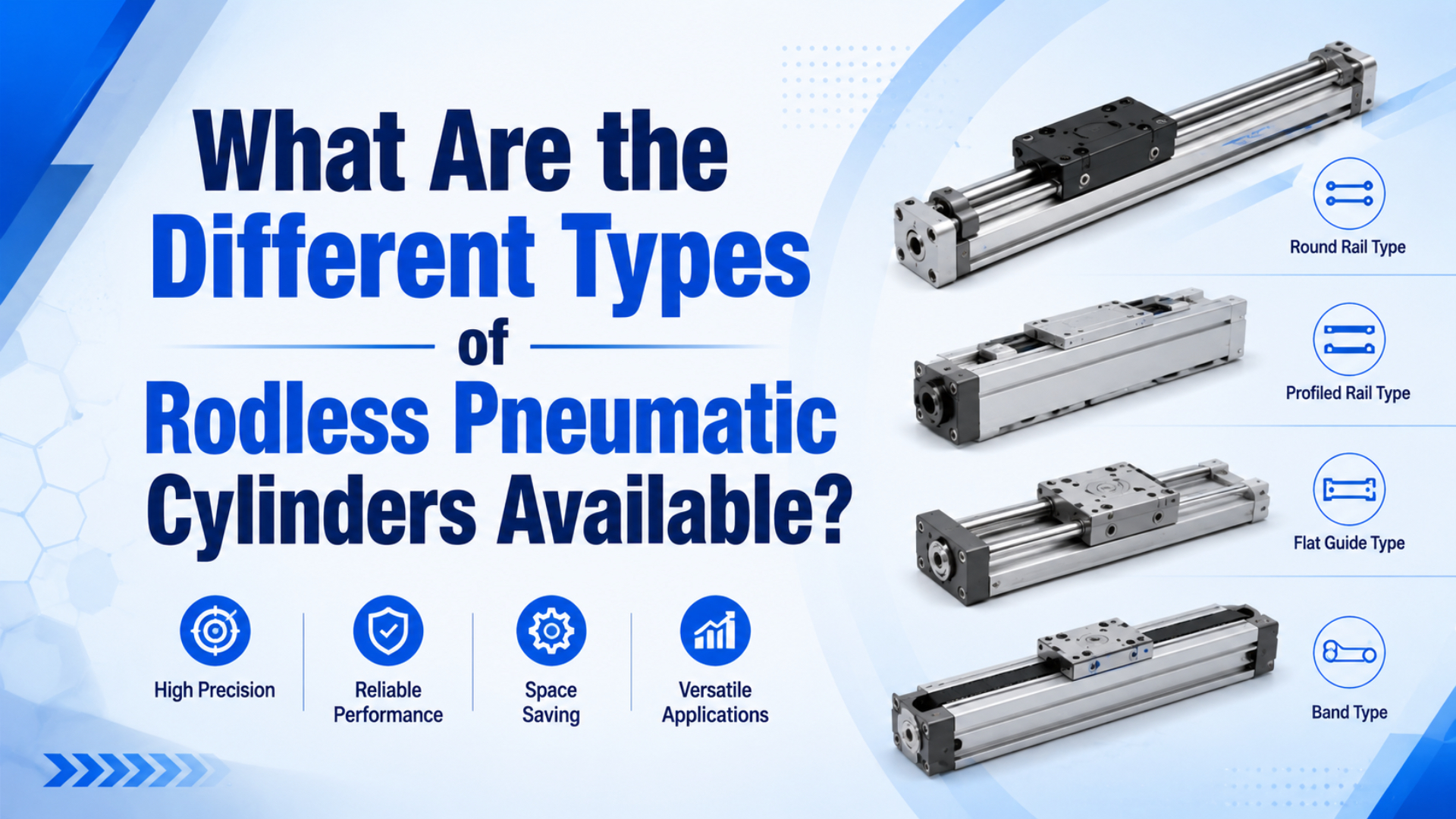
The main rodless pneumatic cylinder types are magnetic coupling, mechanically jointed or band type, cable-driven long-stroke type, and guided slide or table type. Choose by load path, coupling limit, guide moment, stroke, speed, environment, and maintenance access, not by the product name alone.
That last point matters. Two cylinders can share the same bore and stroke while behaving very differently once the carriage carries an offset load, hits a stopper, or runs through a dirty packaging line. The right question is not only “what type exists?” It is “which type fails last in this machine?”
Key Takeaways
- SMC lists MY1B mechanically jointed rodless cylinders from 10 to 100 mm bore with 0.1 to 0.8 MPa operating pressure (SMC MY1 catalog, 2015, retrieved 2026).
- Magnetic types keep the pressure tube closed, while mechanical and guided types give stronger direct load handling.
- Use force, guide moment, flow, and environment checks before comparing price.
What Are the Main Rodless Pneumatic Cylinder Types?
Use four buckets first: magnetic coupling, mechanically jointed or band, cable-driven, and guided slide/table. AutomationDirect describes a rodless cylinder as an internal piston connected to an external carriage that moves alongside the cylinder body, which helps compact long linear motion into tighter machine space (AutomationDirect, 2020).
The categories are useful, but they are not equal substitutes. A magnetic type is usually selected for clean, compact motion where coupling slip is acceptable as a protection mode. A mechanically jointed type is selected when the carriage needs a more direct force path. A cable-driven type appears when stroke length dominates the decision. A guided slide type is selected when the load creates pitch, roll, or yaw moment that the cylinder body should not carry by itself.
| Rodless cylinder type | Force transfer | Best fit | Main selection risk |
|---|---|---|---|
| Magnetic coupling | Piston and carriage pull through a closed non-magnetic tube | Clean motion, low to moderate load, no open slot along the tube | Coupling slip if force, acceleration, temperature, or friction exceeds margin |
| Mechanically jointed or band type | Piston connects mechanically to the carriage through a sealed slot or band system | Higher thrust transfer, longer strokes, direct carriage motion | Seal band wear, leakage, misalignment, and maintenance access |
| Cable-driven long-stroke type | Pneumatic piston motion is transferred through cable or pulley hardware | Long travel where carriage mass and installed length matter | Cable tension, stretch, pulley wear, and guarding |
| Guided slide or table type | Rodless cylinder plus built-in slide bearing, cam follower, or linear guide | Offset load, pick-and-place, transfer, and repeatable carriage support | Moment overload, shock at end stroke, guide contamination |
For a definition-first overview, use the companion guide on what a rodless cylinder is. This article is narrower: it compares types by the part of the axis that is most likely to limit the application.
In our experience, the first failed assumption is often the guide, not the bore. A buyer sees a 32 mm bore and expects enough force, but the carriage is carrying a bracket 120 mm away from the slide centerline. That offset creates moment. Bore size does not solve that by itself.
Selection Matrix: Type by Load Path and Failure Mode
SMC’s MY1 selection flow starts with load mass, allowable moment, cushioning, port variation, and switch mounting before the model is final (SMC MY1 catalog, 2015, retrieved 2026). That sequence is a good general rule for all rodless pneumatic cylinder types.
Use the matrix below as a first-pass filter, then verify the chosen catalog family. It deliberately avoids “best type” language because each type is strong under the right constraint.
| If the machine condition is… | Start with this type | Check before buying |
|---|---|---|
| Clean transfer, moderate load, enclosed tube preferred | Magnetic coupling | Coupling force, acceleration, temperature, side load, jam behavior |
| Higher thrust or direct carriage drive required | Mechanically jointed or band | Seal strip life, leakage path, dust band, lubrication rule, service access |
| Very long stroke with low carriage force | Cable-driven long-stroke | Cable tension schedule, guarding, pulley access, speed stability |
| Load is offset from carriage centerline | Guided slide or table | Pitching, rolling, yawing moment, static load, dynamic stopper load |
| Existing rodded cylinder makes the machine too long | Rodless cylinder product family | Installed length, end-cap space, tubing route, sensor position |
| Two-position transfer with stable plant air | Pneumatic rodless axis | Cushioning, valve flow, end-stop impact, air consumption |
| Programmable stops and position profiles are required | Compare electric actuator too | Feedback, servo profile, holding force, controller cost |
This is also where cannibalization with other rodless content is easy. The broader rodless actuator guide compares pneumatic and electric actuator families. This page stays on pneumatic rodless cylinder types and their physical limits.
How Should You Choose Between Magnetic and Mechanically Jointed Types?
SMC’s basic MY1B mechanically jointed rodless cylinder specification lists 0.1 to 0.8 MPa operating pressure, 1.2 MPa proof pressure, and non-lube operation with air as the fluid (SMC MY1 catalog, 2015, retrieved 2026). Those numbers set the pressure envelope, but they do not choose the coupling.
Choose a magnetic rodless cylinder when the closed tube is a real advantage. The pressure tube has no long slot, so the design can be cleaner around dust-sensitive or wipe-down areas. Magnetic coupling also gives a visible failure mode: if the load jams badly enough, the carriage can lose magnetic sync instead of forcing every part to absorb the jam.
That protection has a price. The available carriage force is limited by the magnetic coupling, not only by piston area. If your fixture drags, the conveyor rail is dirty, or acceleration is aggressive, the cylinder can feel weak even when the bore looks large enough on paper. For a deeper physics-first explanation, see the magnetic rodless cylinder guide.
Choose a mechanically jointed or band type when the load needs a more direct force path. The piston connection is mechanical, so the design is usually better suited to higher thrust transfer and heavier carriage work. The tradeoff is the sealing system. A band, seal strip, dust strip, and carriage slot need alignment and inspection.
When we review replacement photos, a mechanically jointed cylinder often tells its own story. Scratches on the dust band, uneven carriage wear, or a shiny track at one end usually point to alignment and stopper impact before they point to the valve.
| Decision question | Magnetic coupling answer | Mechanically jointed answer |
|---|---|---|
| Is a closed pressure tube valuable? | Yes, this is the main reason to consider it | No, the slot or band system is part of the design |
| Can coupling slip be tolerated? | It must be planned for | Usually not the intended failure mode |
| Is direct thrust transfer more important? | Only if coupling margin is large enough | Usually stronger fit |
| Is maintenance access limited? | Fewer slot-related checks | Band and seal access matter |
| Is the environment abrasive? | Protect the carriage and guide | Protect band, seal strip, and guide surfaces |
When Does a Guided Rodless Cylinder Make More Sense?
SMC’s MY1 family names five guide choices: basic, slide bearing guide, cam follower guide, linear guide, and high-rigidity linear guide (SMC MY1 catalog, 2015, retrieved 2026). That catalog structure shows why “rodless cylinder type” and “guide type” should be checked together.
A bare rodless cylinder moves a carriage. It is not automatically a precision linear guide. If the load is centered, light, and separately supported, a basic unit can work. If the load hangs off a bracket, carries tooling, or stops against hard end blocks, the guide becomes the axis.
SMC’s model-selection pages calculate load mass, static moment, dynamic moment, and a summed guide load factor. In one worked MY1H example, the selected axis is accepted because the sum of guide load factors is 0.60, below the limit of 1.0 (SMC MY1 catalog, 2015, retrieved 2026). The lesson is not that 0.60 applies to your machine. The lesson is that moment load must be calculated, not guessed.
Choose a guided rodless cylinder when any of these are true:
| Condition | Why the guide matters |
|---|---|
| The load center is offset from the carriage centerline | Offset creates pitching, rolling, or yawing moment |
| The machine has vertical or wall mounting | Gravity changes the moment direction |
| The carriage hits a stopper | Dynamic moment can exceed static moment |
| The tooling must stay square | Bearing play and table accuracy matter |
| Long stroke causes tube sag | Side supports or stronger guides may be needed |
The rodless air slide article explains this mechanism in more detail if the buyer uses “air slide” as the product name. Use how a rodless air slide works when the main question is carriage guidance rather than type taxonomy.
What Stroke, Speed, and Pressure Checks Matter?
For MY1B, SMC lists bore sizes from 10 to 100 mm, standard strokes up to 5000 mm for larger basic types, and operating pressure from 0.1 to 0.8 MPa (SMC MY1 catalog, 2015, retrieved 2026). Those values are catalog limits, not permission to ignore flow.
The force estimate starts with piston area and pressure. SMC states the theoretical output formula as pressure in MPa multiplied by piston area in mm2, giving force in newtons. That is only the starting number. Friction, seal drag, coupling loss, guide load, acceleration, and cushion behavior reduce what the machine feels.
For speed, check air path before blaming the cylinder. A long rodless axis can have more chamber volume, longer tubing, and more exhaust restriction than a short compact cylinder. If the valve sits far from the actuator, the cylinder may meet its bore and pressure requirements but miss cycle time.
Use these checks before ordering:
| Check | Why it matters | Data to collect |
|---|---|---|
| Bore and working pressure | Sets theoretical piston force | Bore, pressure at actuator during motion, load force |
| Coupling or joint capacity | Limits transmitted carriage force | Coupling rating, mechanical joint style, safety factor |
| Stroke and installed length | Decides whether rodless is useful | Required travel, end-cap allowance, sensor space |
| Piston speed | Drives flow, impact, and guide load | Target stroke time, load mass, cushion type |
| Valve and tube flow | Prevents slow or uneven motion | Valve Cv or flow, tube ID, tube length |
| Cushioning and stopping | Protects carriage and guide | Moving mass, speed, stopper position, shock absorber |
If the application is mostly a pressure problem, pair this article with air cylinder working pressure. If it is a product-family problem, compare rodless cylinder options, OSP-P modular rodless cylinders, DGC rodless cylinders, and MY1H guided rodless cylinders.
Which Type Fits Dirty, Clean, or Long-Stroke Environments?
ISO 8573-1:2010 classifies compressed-air purity by particles, water, and oil (ISO, 2010). That three-part contamination model is practical for rodless cylinders because seals, bands, magnets, cable hardware, and guide bearings all react differently to dirt and moisture.
For clean but not high-force motion, magnetic coupling can be attractive because the pressure tube stays closed along the stroke. Keep ferrous dust, side load, and temperature in mind. Magnets do not fix an overloaded guide, and they do not like abrasive debris on the external carriage path.
For dusty packaging, woodworking, ceramics, or cutting areas, a mechanically jointed or guided type needs better protection and easier inspection. Dust bands and seal strips should be visible enough to inspect during maintenance. If the band is buried inside guarding that nobody removes, the design is only serviceable on paper.
For very long travel, cable-driven or long-stroke mechanical designs need a different maintenance mindset. Cable tension, pulley alignment, sag, and guarding become part of the actuator decision. In that case, ask whether pneumatic motion is still the simplest answer or whether an electric belt axis makes more sense.
A useful field test is to ask maintenance how they will clean the stroke path. If the answer requires removing a machine panel, a hidden band or exposed guide may become the real cost driver.
| Environment | Better starting point | Avoid if… |
|---|---|---|
| Clean assembly or inspection station | Magnetic or guided slide | Coupling force is close to required thrust |
| Dusty packaging or cutting area | Protected mechanical or guided type | Band and guide cannot be inspected |
| Long transfer stroke | Cable-driven or long-stroke mechanical | Cable tension cannot be maintained safely |
| Offset pick-and-place load | Guided slide or table | Load moment is not calculated |
| Washdown or wet area | Protected design with correct seals and air prep | Water can sit on guide surfaces or bands |
| Vertical lift | Guided type plus load-holding safety review | Air loss could drop the load |
RFQ Checklist for Rodless Pneumatic Cylinder Types
SMC’s MY1 model-selection sequence asks for load mass, speed, pressure, mounting orientation, guide moment, cushioning, ports, and switch mounting (SMC MY1 catalog, 2015, retrieved 2026). An RFQ that omits those fields forces the supplier to guess the cylinder type.
Send the information below when asking for a replacement or new selection. It shortens the conversation and reduces the risk of comparing a bare cylinder against a guided axis.
| RFQ field | Why it changes the type |
|---|---|
| Current model number or photos | Identifies magnetic, mechanical, guided, cable, or custom construction |
| Stroke and installed length | Confirms whether rodless geometry solves the space issue |
| Bore or tube size | Anchors force estimate and product-family matching |
| Working pressure at the actuator | Prevents sizing from regulator pressure alone |
| Moving mass and load offset | Determines guide moment and carriage load |
| Mounting orientation | Changes gravity load and moment direction |
| Target stroke time or speed | Sets valve, tube, cushion, and impact checks |
| End-stop method | Separates air cushion, shock absorber, and external stopper needs |
| Environment | Drives seal, band, guide, corrosion, and air-quality choices |
| Sensor and switch requirements | Affects magnet, slot, and mounting compatibility |
For replacement work, include a short note about what failed. “Leaks at band after six months” points in a different direction than “carriage slips under acceleration” or “axis reaches only 70 percent of expected speed.” Those symptoms help decide whether the next part should be the same type, a guided version, or a different actuator family.
FAQs About Rodless Pneumatic Cylinder Types
This FAQ keeps the answer set narrow so it does not repeat the broader rodless-cylinder articles. SMC’s MY1 catalog alone lists five guide variants and 10 to 100 mm bores in the basic family range (SMC MY1 catalog, 2015, retrieved 2026).
What is the best rodless pneumatic cylinder type?
There is no universal best type. Magnetic coupling is useful for cleaner closed-tube motion, mechanically jointed types suit stronger direct drive, cable-driven types suit long travel, and guided slides suit offset loads. Start with load path, moment load, stroke, speed, environment, and maintenance access.
Are magnetic rodless cylinders weaker than mechanical types?
They can be lower in usable carriage force because the magnetic coupling sets a real transfer limit. That does not make them poor products. It means they should be selected where a closed tube, clean motion, and controlled load are more important than maximum direct thrust.
When should I choose a guided rodless cylinder?
Choose a guided type when the load is offset, tooling must stay square, the axis is wall-mounted or vertical, or the carriage stops against end hardware. SMC’s selection process checks static and dynamic moment because a load can pass the mass limit and still fail the moment check.
Do rodless cylinders need special valve sizing?
They need ordinary pneumatic sizing done carefully. Long stroke, large bore, long tubing, and fast stroke time can raise flow demand. Use bore, stroke, pressure, target stroke time, valve flow, tube ID, and cushion behavior together instead of sizing only from pressure.
What should I send for a rodless cylinder replacement quote?
Send the current model or photos, bore, stroke, pressure, moving mass, load offset, mounting orientation, target speed, valve and tube details, sensor requirements, end-stop method, environment notes, and the failure symptom. That package lets the supplier compare type, guide, and air path together.
Source notes: SMC MY1 mechanically jointed rodless cylinder catalog, pressure, bore, stroke, guide-family, force formula, and guide-load selection data, retrieved 2026-07-08. AutomationDirect rodless cylinder overview, compact carriage explanation and publication metadata, retrieved 2026-07-08. ISO 8573-1 standard page, compressed-air purity classes by particles, water, and oil, retrieved 2026-07-08. Enfield Technologies video, rodless cylinder positioning demo, retrieved 2026-07-08.