

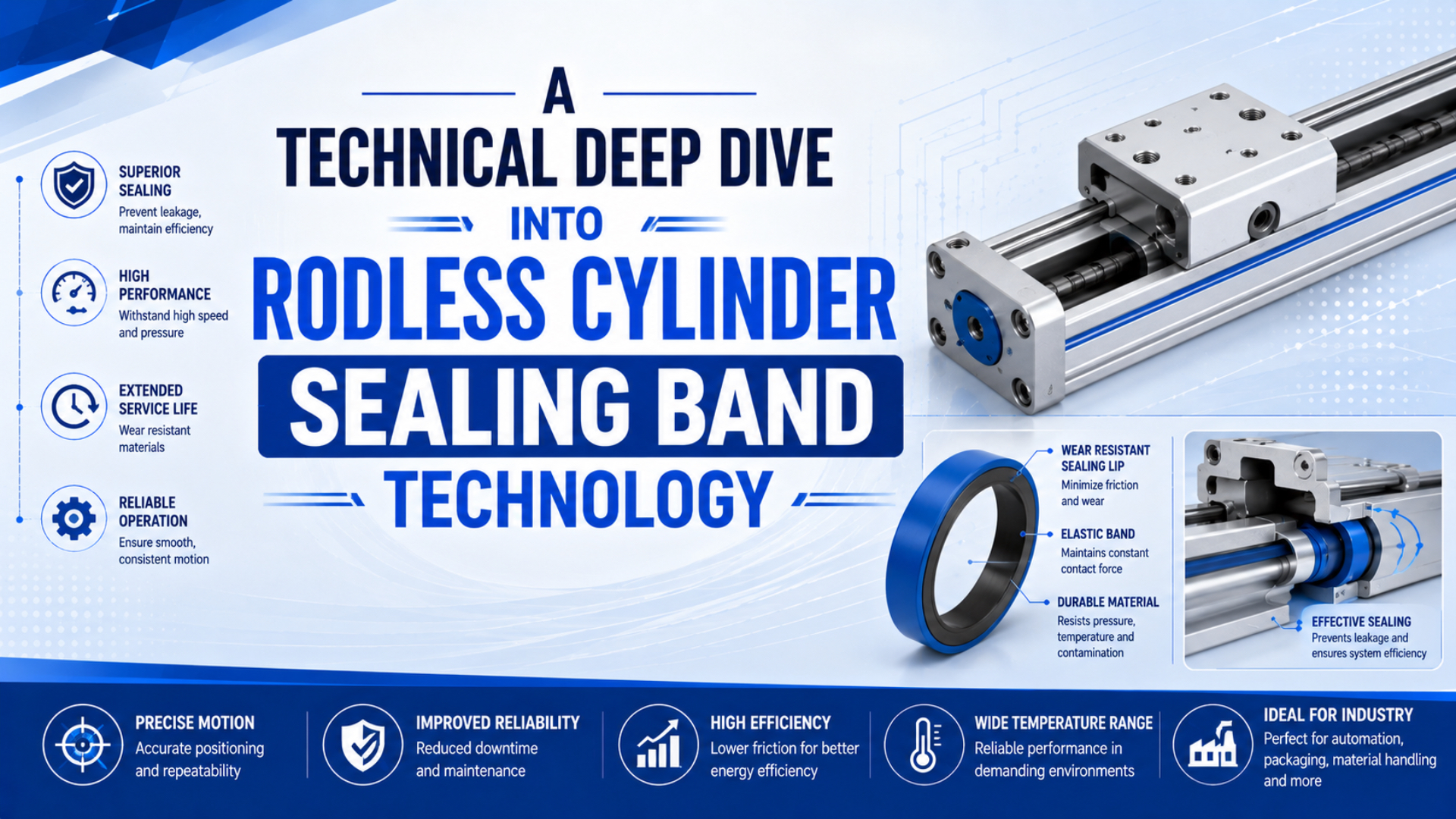
Rodless cylinder sealing band technology is the slot-sealing system used on mechanically jointed rodless cylinders, not the same thing as magnetic coupling. In other words, the band closes the long opening in the cylinder body while the piston and carriage move, so the useful service question is leakage, contamination, alignment, and replacement fit.
That distinction matters. A magnetic rodless cylinder can transfer motion through a closed tube. A mechanically jointed rodless cylinder must control a moving slot. If the article treats both as one design, engineers can diagnose the wrong failure path and order the wrong spare parts.
Key Takeaways
- SMC lists MY1 mechanically jointed rodless cylinders with 10-100 mm bores and 0.1-0.8 MPa operating pressure.
- Magnetic rodless cylinders use a closed, hermetically sealed pneumatic space, so their leakage path differs from band-style designs.
- Test suspected seal-band leakage with isolation, pressure decay, visual band inspection, and guide alignment before replacing the valve.
Rodless cylinder sealing band is the long sealing strip or band system that closes the slot on a mechanically jointed rodless cylinder while the carriage moves. Specifically, mechanically jointed rodless cylinder is a rodless actuator where the piston is physically connected to the outside carriage through that sealed slot. Pressure-decay leak testing is a simple isolation test that estimates leakage from known volume, pressure drop, and elapsed time.
In our experience, the best first question is not “What material is the band?” It is “Where is the pressure escaping?” For example, a scratched outer dust band, a weak valve spool, and a damaged inner pressure band can all sound like the same hiss until the axis is isolated and tested.
Short Answer: Sealing Bands Belong to Slotted Rodless Cylinders
SMC’s MY1 catalog identifies the family as a mechanically jointed rodless cylinder, with bore sizes from 10 mm to 100 mm and an operating pressure range of 0.1 to 0.8 MPa (SMC MY1 catalog, 2015, retrieved 2026-07-08). That is the design family where seal-band diagnosis belongs.
In a slotted rodless cylinder, the piston is mechanically connected to the external carriage through a lengthwise opening. The seal band closes that opening before and after the carriage passes. Depending on the product family, you may also see the terms inner seal strip, outer cover strip, dust band, sealing strip, or stainless steel band.
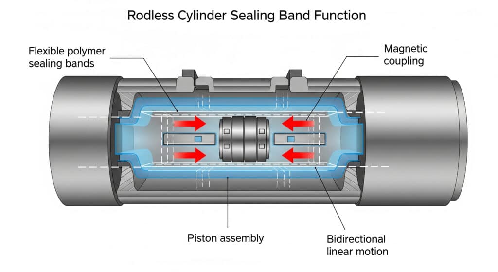
The important point is functional, not lexical. One band or strip helps preserve pressure inside the working chamber. Meanwhile, another visible strip may protect the slot from contamination. Therefore, a replacement review must confirm which part failed before ordering a kit.
For the broader category comparison, use the guide to rodless pneumatic cylinder types. For seal-family vocabulary, use the companion guide to industrial cylinder seal types. This article stays narrower: band-style rodless cylinder leakage and replacement.
Why Is a Magnetic Rodless Cylinder Not the Same Design?
Festo describes magnetically coupled rodless cylinders as linear actuators whose slide is moved by magnetic coupling, with the pneumatic space closed and hermetically sealed (Festo, retrieved 2026-07-08). That closed-tube design should not be diagnosed as a long slotted sealing-band system.
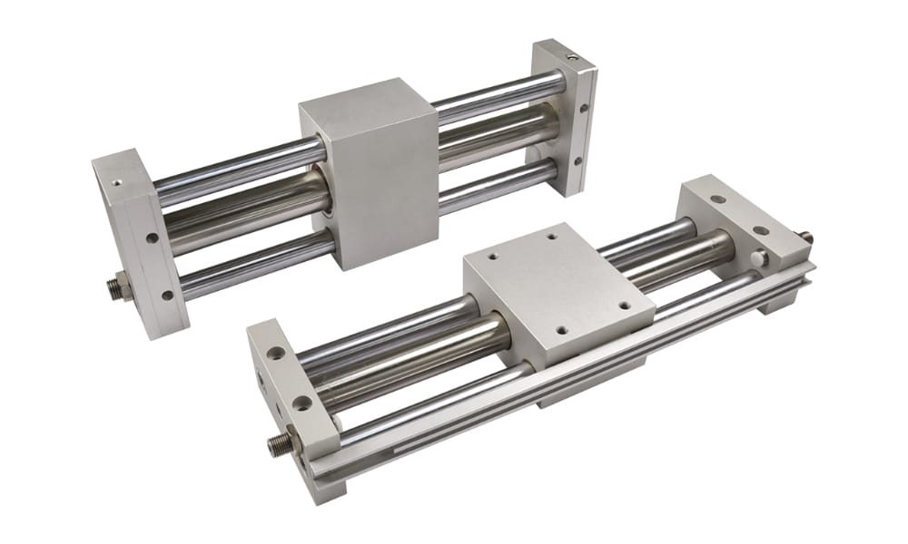
A magnetic rodless cylinder can still leak at ports, end seals, piston seals, or damaged tube interfaces. However, it does not use the same long slot closure that a mechanically jointed cylinder uses. Consequently, if a maintenance report says “seal band” while the installed actuator is magnetic, stop and identify the exact series before ordering parts.
Therefore, use this split during troubleshooting:
| Installed rodless type | Pressure tube | Main motion transfer | Seal-band relevance | First leakage check |
|---|---|---|---|---|
| Magnetic coupling | Closed tube | Magnetic attraction through the tube wall | Usually not a long slot band issue | Ports, piston seal, end seals, tube damage |
| Mechanically jointed or band type | Slotted tube | Mechanical link through the slot | Primary diagnostic area | Inner pressure band, outer dust band, slot, carriage seal |
| Guided rodless slide | Depends on cylinder core | Cylinder plus guide system | Depends on core design | Seal band plus guide alignment and stopper impact |
| Cable-driven rodless axis | Product-specific | Cable or pulley transfer | Product-specific | Cable path, piston seals, end seals, fittings |
When replacement photos show a clean closed tube, we do not start with seal-band material. Instead, we start with the model label. The wrong mental model can turn a simple end-seal or port-leak problem into a long search for a band that the actuator never had.
For the magnetic design itself, read the dedicated magnetic rodless cylinder guide.
How Do the Inner Band, Outer Band, and Carriage Slot Work Together?
SMC lists a dust seal band and NBR lining among MY1 series features, while the same specification table gives 5 to 60 deg C ambient and fluid temperature data for the basic series (SMC MY1 catalog, 2015, retrieved 2026-07-08). Those details show that sealing is a mechanical package, not just one rubber strip.
The pressure side and the contamination side have different jobs. In contrast, the pressure band must keep compressed air inside the cylinder chamber while flexing around the moving connection point. The outside band or dust cover protects the slot from fibers, grit, coolant mist, washdown residue, and handling damage.
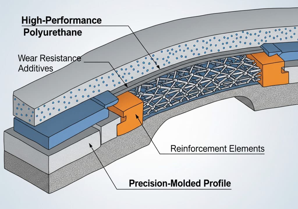
The carriage creates the difficult part. As it moves, the band must open locally, pass around the connection geometry, and return to a sealed position behind the carriage. As a result, alignment, debris, and guide moment matter as much as material grade.
Common parts in a band-style rodless cylinder include:
| Part | Job | What goes wrong |
|---|---|---|
| Inner pressure band or seal strip | Closes the pressurized slot | Nicking, loss of seating, extrusion, permanent set |
| Outer dust band or cover strip | Keeps contamination away from the slot | Scratches, dents, debris trapped under the strip |
| Carriage seal interface | Lets the carriage pass while managing the open section | Uneven wear, air hiss near carriage, friction spike |
| Guide or bearing system | Carries external load and moment | Misalignment, side load, stopper impact |
| End seals and ports | Seal fixed joints and air connections | Fitting leaks, cap seal damage, thread seal issues |
The band is often blamed last because it is long and awkward to replace. Similarly, it is also blamed too early because it is visible. A better rule is this: visible damage is evidence, but a pressure-decay test tells you whether that damage is actually leaking.
What Failure Signs Point to the Sealing Band Instead of the Valve?
ISO 8573-1 specifies compressed-air purity classes for particles, water, and oil, and it also identifies gaseous and microbiological contaminants (ISO 8573-1, 2010, retrieved 2026-07-08). Those 3 common contaminant groups are a practical starting point when a rodless cylinder slot begins to hiss or drag.
A valve problem usually affects how air is supplied, exhausted, or held. In contrast, a sealing-band problem usually follows the carriage position, the slot length, or a damaged section of band. That is why the test needs to separate circuit leakage from actuator leakage.
Specifically, use this first-pass symptom map:
| Symptom | More likely source | How to separate it |
|---|---|---|
| Hiss follows the moving carriage | Seal band, carriage seal, or slot interface | Move slowly and listen along the carriage path |
| Hiss remains at one end cap | Port, cap seal, cushion seal, or fitting | Soap test fittings and cap joints first |
| Cylinder drifts with valve blocked | Internal bypass or seal-band leakage | Isolate the actuator and run pressure decay |
| Carriage sticks at the same stroke location | Dirt, band damage, guide damage, or dented slot | Inspect the same physical location each cycle |
| Both directions are slow | Supply pressure, valve flow, tubing, muffler | Compare point-of-use pressure and exhaust restriction |
| New band fails quickly | Alignment, guide moment, installation damage | Check rail straightness, stopper impact, carriage load |
For pressure behavior, the companion article on air flow and pressure conversion helps separate a real pressure loss from a flow-starved circuit. For air quality, see the guide to ISO compressed air quality standards.
Which Operating Conditions Shorten Seal Band Life?
Parker’s OSP-P catalog warns that load and moment data are based on speeds v <= 0.5 m/s and that friction forces from the specific application or load must be considered (Parker OSP-P catalog, 2025, retrieved 2026-07-08). That warning applies directly to seal-band life.
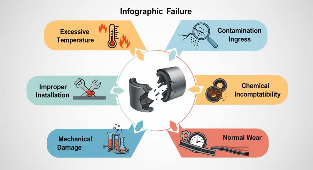
A seal band is not a free-standing wear part. Instead, it reacts to the entire axis: pressure, speed, carriage load, guide moment, stopper impact, air quality, temperature, cleaning chemicals, and installation method. If any of those inputs are outside the catalog envelope, replacing the band alone may only reset the countdown.
For instance, the most common life-shortening conditions are:
- Contaminated slot area. Dust, fibers, metal chips, and dried washdown residue can score the band or hold it open.
- Poor guide alignment. A carriage that twists the connection point can overload one edge of the band.
- Excessive speed or impact. Higher approach speed raises cushion load and can shake the band or guide package.
- Wrong replacement band. Similar width is not enough; profile, material, thickness, and end treatment must match.
- Chemical mismatch. Coolant, cleaners, oil mist, or process vapor can swell or harden some elastomers.
- Rough handling during installation. Sharp slot edges, screwdrivers, and over-stretching can damage a new band before startup.
Seal-band diagnosis also overlaps with end-of-stroke behavior. If the carriage slams into hard stops, review pneumatic cylinder cushioning before blaming the band material.
How Should Maintenance Teams Test and Replace the Band?
The pressure-decay method uses 4 inputs: isolated system volume, start pressure, end pressure, and elapsed time. For a 500 L isolated volume, a drop from 7.0 bar to 6.5 bar over 10 minutes is enough data to estimate leakage before replacing parts.
Start with isolation. First, shut off production demand, lock out the machine according to site procedures, and isolate the axis or branch being tested. Then check simple external leaks at fittings, valve manifolds, cushion screws, and end caps. Only after those are clear should the seal band become the lead suspect.
Accordingly, use this sequence:
- Record the cylinder brand, series, bore, stroke, mounting orientation, and serial label.
- Photograph the full axis, both ends, the carriage, and any visible band damage.
- Clean the slot area with the manufacturer-approved method, not a sharp tool.
- Move the carriage slowly through the full stroke and mark locations where hiss or drag repeats.
- Block or isolate the valve where safe so circuit leakage is separated from actuator leakage.
- Run a pressure-decay test on a known volume and record start pressure, end pressure, and time.
- Inspect guide play, stopper impact, bracket overhang, and carriage alignment before installing a new band.
We found repeat band failures caused by one missing note in the RFQ: the carriage was mounted vertically with an offset load, but the buyer only sent bore and stroke. The replacement band fit the slot. Nevertheless, it failed because the guide load problem was unchanged.
For long-stroke support and load direction, the rodless air slide guide is the closest companion article.
RFQ Checklist for Replacement Sealing Bands
SMC’s selection flow reviews load mass, allowable moment, cushioning at stroke end, port variations, and auto switch mounting before a MY1 model is selected (SMC MY1 catalog, 2015, retrieved 2026-07-08). A replacement RFQ should send the same kind of context, not just a strip length.
In addition, send these items with the inquiry:
| RFQ item | Why it matters |
|---|---|
| Cylinder brand, series, bore, and stroke | Confirms the sealing-band profile and end treatment |
| Photos of the nameplate and carriage | Prevents confusion between magnetic, band, cable, and guided types |
| Photos of the damaged band and slot | Shows scoring, tearing, denting, contamination, and installation damage |
| Working pressure and pressure unit | Checks the seal against the real operating envelope |
| Speed or stroke time | Helps review friction, heat, and end-stop impact |
| Load mass and bracket offset | Reveals guide moment that can destroy the band |
| Air quality and lubrication condition | Connects failure to particles, water, oil, or dry running |
| Temperature, washdown, and chemicals | Screens material compatibility before shipment |
| Failure symptom and location | Separates local slot damage from whole-circuit leakage |
| Replacement history | Flags repeat failure and possible alignment causes |
Notably, the fastest useful RFQ includes 6 photos: full axis, nameplate, carriage close-up, damaged band, both end caps, and the installed load bracket. A short video of one slow stroke is even better when the carriage sticks or hisses at the same location.
From our work, the model label and carriage photos are usually more useful than a guessed material name.
For direct support, use the contact page and include the information above. For company background and engineering scope, see About Us.
FAQs About Rodless Cylinder Sealing Band Technology
These 5 answers are written for maintenance and purchasing teams that need a practical decision before sending photos or ordering parts. They assume a mechanically jointed or slotted rodless cylinder unless the answer specifically mentions magnetic coupling.
Does every rodless cylinder have a sealing band?
No. Magnetic rodless cylinders use a closed pneumatic tube with magnetic force transfer, while mechanically jointed or band-style designs use a slotted body that needs a sealing system. Festo describes magnetic types as closed and hermetically sealed, so identify the cylinder series before ordering a seal band.
Can a damaged outer dust band cause air leakage?
Sometimes, but not always. The visible outer band may mainly protect the slot from contamination, while the inner pressure band controls the air seal. If the outer band is scratched, inspect the inner sealing path and run pressure decay before assuming the visible damage is the pressure leak.
What is the best test for seal-band leakage?
Use isolation plus pressure decay. Record known system volume, start pressure, end pressure, and elapsed time, then compare the result with a visual inspection along the carriage path. A hiss that follows carriage position is stronger evidence than a general pressure drop in the whole pneumatic circuit.
Why do new sealing bands fail quickly?
Fast repeat failure usually means the original cause was not removed. Check guide alignment, bracket overhang, dirty slot areas, hard end-stop impact, chemical exposure, and installation damage. Parker warns that application friction forces must be considered, which is exactly where repeat band failures often start.
What information should I send for a replacement sealing band quote?
Send the cylinder brand, model, bore, stroke, pressure, speed or stroke time, load mass, mounting orientation, photos of the band and nameplate, and a short description of the failure symptom. Photos matter because magnetic, mechanically jointed, guided, and cable-driven rodless cylinders use different sealing assumptions.
Source Notes
The source list below separates pneumatic-cylinder failure diagnosis from unrelated cutting-tool data references; ISO/TS 13399-312:2016 should not be used as evidence for rodless-cylinder sealing failures.
- SMC MY1 mechanically jointed rodless cylinder catalog, 2015, retrieved 2026-07-08. Used for bore range, operating pressure, proof pressure, temperature, dust seal band wording, and selection-flow factors.
- Parker Origa OSP-P catalog, 2025, retrieved 2026-07-08. Used for load, moment, speed, friction, and cushioning cautions.
- Festo magnetically coupled cylinders, retrieved 2026-07-08. Used to separate closed-tube magnetic rodless cylinders from slotted sealing-band designs.
- ISO 8573-1:2010, retrieved 2026-07-08. Used for compressed-air contaminant categories: particles, water, oil, and additional contaminants.
- AutomationDirect rodless cylinder overview, 2020, retrieved 2026-07-08. Used for the compact-linear-motion context of rodless cylinders.