

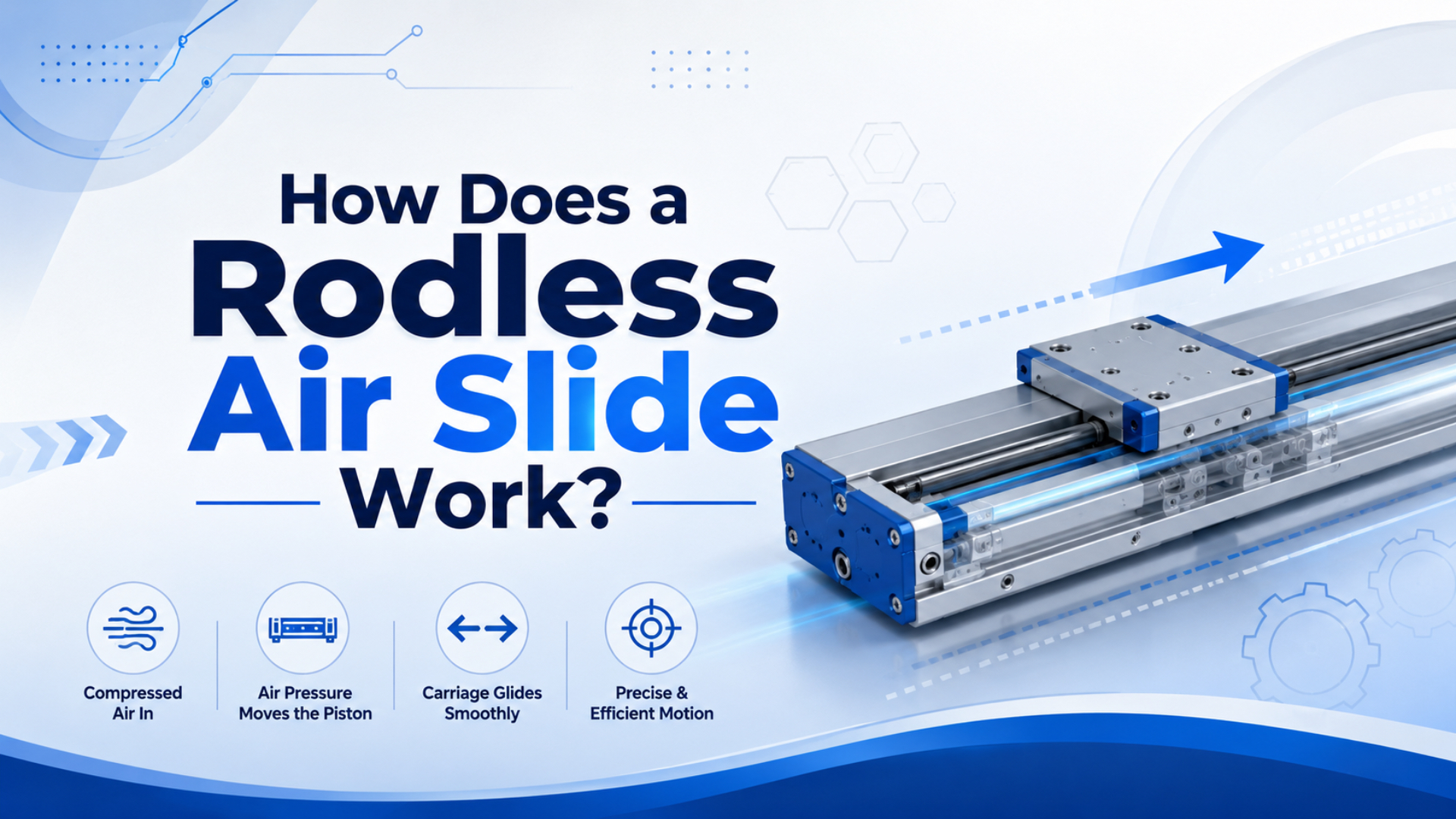
A rodless air slide works by using compressed air to move an internal piston while an external carriage carries the load along a guided path. The piston force reaches the carriage through a magnetic coupling, a mechanical band, or a sealed joint. The visible result is straight-line motion without a piston rod projecting beyond the actuator body.
That missing rod is the whole point.
A conventional rod cylinder needs room for the cylinder body and the extended rod. A rodless cylinder keeps the moving carriage beside the cylinder barrel, so long strokes fit into shorter machine envelopes. The tradeoff is selection discipline: the carriage, guide, coupling, air path, and end cushioning all need to match the load.
Key Takeaways
- Parker lists OSP-P standard stroke choice up to 6000 mm and long-stroke versions up to 41 m.
- SMC lists 0.1-0.8 MPa operating pressure and 100-1000 mm/s piston speed for one MY1B guided rodless specification.
- Select the slide by load moment and force transfer method, not only by bore and stroke.
What Is a Rodless Air Slide?
Rodless air slide is the practical name for a guided pneumatic linear actuator with no exposed piston rod. AutomationDirect describes rodless cylinders as using an internal piston connected to an external carriage that moves alongside the cylinder body, helping the actuator fit tighter spaces than a rodded cylinder (AutomationDirect, 2020).
Think of it as a small linear axis powered by air. The air pressure creates force inside the cylinder. The carriage carries the tool, fixture, pusher, stopper, or workpiece outside the cylinder. The guide system keeps the load from twisting the moving parts.
This is where many selection mistakes start. The buyer asks for an “air slide,” but that phrase can mean a compact slide table, a guided cylinder, or a rodless cylinder with a carriage. This article focuses on the rodless version: the actuator that moves a load without sending a rod past the machine frame.
For broader air-slide terminology, use the companion article on air slide function in industrial applications. Here, the narrower question is force transfer. How does a hidden piston move a visible carriage?
How Does the Piston Move the External Carriage?
The internal piston moves because compressed air fills one cylinder chamber and exhausts the other. Parker’s OSP-P rodless actuator family is published in bore sizes from 10 to 80 mm and standard strokes up to 6000 mm (Parker OSPP Series, 2026). The carriage follows that piston through the selected coupling design.
The basic sequence is simple:
- A directional valve sends compressed air to one side of the piston.
- Pressure acts on the effective piston area and creates linear force.
- The opposite chamber exhausts through the valve and muffler.
- The piston moves along the cylinder bore.
- A magnetic or mechanical connection transfers that motion to the external carriage.
- The guide system carries side load and moment while the carriage travels.
The force math still starts with Force = Pressure x Effective piston area. That formula is useful for a first pass, but it is not enough for selection. Seal drag, pressure drop, coupling loss, guide friction, moving mass, stop impact, and mounting stiffness all subtract from the clean classroom answer.
The practical check is this: a rodless air slide is not one component doing one job. It is three jobs packaged together. Air creates thrust, the coupling transfers thrust, and the guide protects the motion. When one of those jobs is undersized, the whole axis feels weak.
Which Force Transfer Mechanism Fits the Job?
Rodless air slides transfer force by magnetic coupling, mechanically jointed bands, cables, or carriage linkages. SMC’s MY1B new basic type lists bore sizes of 25, 32, and 40 mm and reports load-mass and allowable-moment increases up to 30% versus the previous MY1B (SMC, 2026).
Magnetic coupling is clean because the piston and external carriage do not need a physical slot through the pressure tube. Magnets pull the carriage along through a non-magnetic wall. If the load jams, the coupling can slip before the structure breaks. That is useful protection, but it also means the coupling force is a real limit.
Mechanically jointed and band-type designs use a sealed mechanical connection between the piston and carriage. They usually suit higher force and direct load transfer better than magnetic units. The sealing system is more complex, so air leakage, band wear, and cover-strip condition matter during maintenance.
Cable designs appear in some long-stroke or special layouts. They can redirect force through pulleys or compact routing, but cable tension and pulley wear become part of the inspection plan. Would I default to cable for a standard packaging axis? Usually no. I would use it only when the machine layout makes it worthwhile.
| Force transfer type | Best fit | Main risk | RFQ detail to send |
|---|---|---|---|
| Magnetic coupling | Clean motion, light to moderate load, overload slip protection | Coupling slip if acceleration, friction, or load is too high | Load mass, speed, temperature, side load, expected jam condition |
| Mechanical band or joint | Higher thrust, long stroke, guided carriage motion | Seal wear, band wear, and cover-strip contamination | Stroke, pressure, cycle rate, environment, duty time, mounting orientation |
| Cable transfer | Special routing or unusual machine envelope | Cable stretch, pulley friction, seal difficulty | Layout drawing, pulley location, duty cycle, tension access |
| Guided carriage package | Direct-mounted tooling with side load or moment | Moment overload before thrust limit is reached | Offset distance, pitch moment, roll moment, yaw moment, stop method |
For product-family matching, compare the required force-transfer style before comparing only dimensions. An OSP-P modular rodless cylinder may fit a different problem than a DGC rodless cylinder or an MY1H precision rodless cylinder.
Why Does Removing the Rod Save Machine Space?
Removing the piston rod saves space because the moving member stays beside the cylinder body instead of extending out of it. Parker lists OSP-P maximum standard stroke at 6000 mm and long-stroke versions up to 41 m for larger bore sizes (Parker OSP-P catalog, 2025).
A standard rod cylinder needs room for the barrel, the extended rod, rod-end tooling, and a safety allowance. For long transfer strokes, that can make the machine frame much longer than the useful motion. A rodless air slide keeps the travel over the cylinder body, so the installation length is closer to the stroke plus end caps.
That does not mean rodless is always smaller. Add the carriage height, guide width, sensor space, cable routing, tube bends, and maintenance access. A compact drawing can still become ugly if the fittings point into a guard door.
In our experience with replacement RFQs, the real footprint win often comes from deleting support brackets around the old rod cylinder. If the original machine used an external guide to protect the rod, a guided rodless slide can combine the actuator and guide into a cleaner assembly. But the moment check still decides.
Guides Carry the Load, Not the Air Seal
The guide system carries side load and moment while the air seal only holds pressure. SMC rodless selection data uses load-factor checks for static load and dynamic moment, and warns designers to reduce speed, increase bore size, or revise the guide arrangement when total guide load factor exceeds 1 (SMC catalog PDF, 2024).
This is the most important sentence in the article: do not make the coupling do the guide’s job. The carriage may look strong in a catalog photo, but a tall bracket can create a large pitch moment with a small payload. A light sensor arm mounted far from the carriage can be worse than a heavier plate mounted close.
Check three loads:
- Static load from weight and mounting orientation.
- Dynamic load from acceleration, deceleration, and impact.
- Moment load from overhang in pitch, roll, and yaw directions.
If the load hangs below the carriage, gravity creates moment. If the slide pushes a product off-center, the carriage sees yaw. If the stroke ends against a hard stop at high speed, the guide takes an impact load. That is why catalog speed cannot be copied blindly.
I like to sketch a simple arrow diagram before choosing bore size. One arrow for thrust, one for weight, one for the offset distance, and one for the stop reaction. If the offset arrow looks silly on paper, the guide calculation will probably agree.
How Do You Control Speed and Position?
Speed comes from air flow, exhaust restriction, load, and cushioning, not from pressure alone. SMC’s MY1B catalog lists 0.1-0.8 MPa operating pressure and 100-1000 mm/s piston speed for the referenced mechanically jointed rodless cylinder specification (SMC MY1B catalog, 2025).
Basic two-position control usually uses a solenoid valve, flow control valves, end sensors, and adjustable cushioning. Meter-out flow control is common because restricting exhaust often gives steadier load control than restricting supply air.
Intermediate positioning is different. A basic valve can send the carriage out and back, but it cannot place the carriage anywhere on the stroke by itself. Enfield’s S2 positioning system combines a proportional valve, sensors, and embedded control electronics to position cylinders and actuators from a PLC (Enfield Technologies, 2026).
That distinction matters in quotes. “Stop at both ends” and “stop anywhere along the stroke” are not the same request. The first may need reed switches and cushions. The second may need a servo-pneumatic package, an external position sensor, or an electric actuator instead.
How Should You Size a Rodless Air Slide?
Sizing starts with load path, stroke, pressure, speed, and cushioning, then moves to valve and air-line checks. CAGI says a well-designed compressed-air system should have no more than 10% pressure drop between compressor discharge and any point of use (CAGI, 2026).
Use this early checklist before asking for a part number:
- Stroke and usable travel.
- Moving mass, including tooling and workpiece.
- Mounting orientation: horizontal, vertical, inclined, or inverted.
- Load offset from the carriage centerline.
- Required extend and retract time.
- Available pressure at the actuator during motion.
- Valve type, port size, and tube length.
- Cushioning method, hard stops, and shock absorbers.
- Sensor type: end switch, mid-stroke switch, analog sensor, or external encoder.
- Environment: dust, washdown, food area, cleanroom, heat, or oil mist.
The FRL unit and pressure regulator belong in the sizing conversation. A larger cylinder cannot fix a starved air path. If the pressure drops during motion, the slide may slow down, miss a sensor window, or hit the end stop harder than expected.
For replacement requests, the fastest useful RFQ line is specific: “Stroke 1500 mm, horizontal mount, moving load 12 kg, carriage offset 80 mm, extend time 1.4 s, two end sensors, clean dry air, no washdown.” That gives an engineer enough context to check the slide instead of guessing from a photo.
Common Failure Modes and Fixes
Most rodless air slide faults come from overload, poor air quality, weak exhaust, misalignment, or stop impact. ISO 8573-1:2010 defines compressed-air purity classes by three contaminant groups: particles, water, and oil (ISO 8573-1, 2010). Those contaminants are not abstract when seals and guide surfaces are moving every cycle.
If the carriage slips or loses position, check coupling capacity, acceleration, jam conditions, and guide friction before blaming the valve. Magnetic units can slip when the load exceeds coupling capacity. Mechanical units can bind when the band, seal strip, guide, or mounting is misaligned.
If the slide is slow, measure pressure at the actuator while it moves. A static regulator gauge can look fine while a small valve, long tube, clogged muffler, or dirty filter starves the cylinder. Pressure during motion tells the truth.
If seals fail early, check air quality, lubrication compatibility, side load, and environment. Water and particles are not kind to sliding seals. In washdown or dusty areas, cover-strip condition and wiper design deserve extra attention.
If the end impact is harsh, reduce speed, improve cushioning, add shock absorbers, or use external stops. Do not turn up pressure as the first response. More pressure can increase impact energy and make a marginal guide fail faster.
When Should You Use a Rodless Air Slide?
Use a rodless air slide when the machine needs compact long-stroke linear motion with guided load support. Parker publishes OSP-P theoretical extend force from 47 to 3010 N at 6 bar across its 10 to 80 mm bore range (Parker OSPP Series, 2026). That range fits many transfer and handling jobs.
Good candidates include:
- Long-stroke transfer between conveyors.
- Carton, tray, or pallet pushing.
- Reject stations where a rod would invade guarding.
- Camera or sensor movement across a product path.
- Compact fixture transfer where rod extension is the layout problem.
- Light gantry or shuttle axes that need pneumatic simplicity.
Bad candidates are just as important. Avoid a basic rodless air slide when the application needs many programmable stop points, tight servo profiles, high vertical safety holding, or heavy moment loads beyond the guide rating. A pneumatic axis can be controlled well, but only when the valve, sensor, controller, and actuator are selected as a system.
For nearby engineering context, compare pneumatic cylinder theory and pneumatic cylinder operation. If the project is already at RFQ stage, send the load sketch, stroke, speed, pressure, photos, and environment notes through contact.
FAQs About Rodless Air Slides
These FAQ answers focus on selection facts that buyers usually miss: force transfer, pressure range, guide load, and positioning. Parker lists OSP-P 10 to 80 mm bores and standard strokes up to 6000 mm, while SMC lists 0.1-0.8 MPa operating pressure for one MY1B guided rodless specification (Parker, 2026; SMC, 2025).
Is a rodless air slide the same as a rodless cylinder?
Not always. A rodless cylinder is the actuator family. A rodless air slide usually means the rodless actuator plus a carriage or guide arrangement that carries a load. Some buyers use the terms interchangeably, so confirm whether the quote needs a bare cylinder, a guided carriage, sensors, stops, or mounting hardware.
What pressure does a rodless air slide use?
Pressure depends on the catalog family and the load. SMC lists 0.1-0.8 MPa for one MY1B mechanically jointed rodless specification, while Parker lists 8 bar maximum operating pressure for OSP-P pneumatic rodless cylinders. Always verify pressure at the actuator during motion, not only at the regulator.
Can a rodless air slide stop in the middle of the stroke?
Yes, but not with a plain on-off circuit alone. Intermediate stopping may require external stops, shock absorbers, brakes, a proportional valve, continuous position feedback, or a servo-pneumatic system. Enfield’s rodless-cylinder positioning demo uses external feedback and control hardware, which is the point many RFQs miss.
What fails first on a rodless air slide?
Common early failures are coupling slip, seal leakage, guide wear, hard end impact, and inconsistent speed from air starvation. The root cause is often application mismatch: too much moment, dirty air, poor cushioning, small valves, long tubing, blocked mufflers, or a load mounted too far from the carriage.
What information should I send for a replacement quote?
Send stroke, bore or current model, moving mass, load offset, mounting orientation, speed target, pressure during motion, valve and tube size, sensor type, stop method, cycle rate, photos, and environment notes. For rodless slides, include any guide-load direction and whether the carriage is allowed to slip during a jam.
Sources
These sources were selected for catalog limits, air-system guidance, and positioning examples. The highest-use data points are Parker’s 6000 mm standard stroke and 41 m long-stroke reference, SMC’s 0.1-0.8 MPa MY1B range, CAGI’s 10% pressure-drop guidance, and ISO 8573-1’s 3 contaminant groups.
-
AutomationDirect: Rodless Cylinders Provide a Compact Pneumatic Linear Motion Option, explanation of internal piston and external carriage construction. Retrieved 2026-06-03.
-
Parker: OSPP Series, bore sizes, 6000 mm maximum standard stroke, and theoretical force range at 6 bar. Retrieved 2026-06-03.
-
Parker: OSP-P Pneumatic Rodless Cylinders and Linear Guides catalog, 8 bar maximum operating pressure, load and moment guidance, and long-stroke versions up to 41 m. Retrieved 2026-06-03.
-
SMC: Mechanically Jointed Rodless Cylinder Basic Type MY1B, bore sizes and up to 30% load-mass and allowable-moment increase for the new MY1B. Retrieved 2026-06-03.
-
SMC: MY1B Mechanically Jointed Rodless Cylinder catalog, 0.1-0.8 MPa operating pressure and 100-1000 mm/s piston speed data. Retrieved 2026-06-03.
-
SMC: MY1B-Z mechanically jointed rodless cylinder selection data, guide load factor and dynamic moment selection guidance. Retrieved 2026-06-03.
-
CAGI: Working With Compressed Air, 10% pressure-drop guidance from compressor discharge to point of use. Retrieved 2026-06-03.
-
ISO 8573-1:2010, compressed-air purity classes for particles, water, and oil. Retrieved 2026-06-03.
-
Enfield Technologies: S2 Low-Flow Cylinder Positioning System, proportional valve, sensors, and embedded control electronics for pneumatic positioning. Retrieved 2026-06-03.
-
Enfield Technologies video: S2 Positioning - Better Rodless Cylinder Positioning, rodless cylinder positioning demo with external feedback. Retrieved 2026-06-03.