

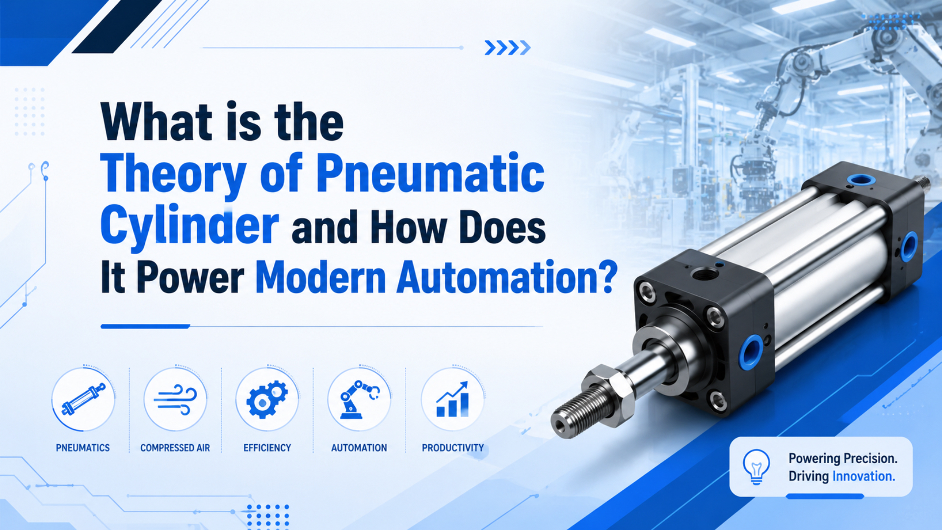
Pneumatic cylinder theory explains how compressed air becomes linear motion. The short version is simple: pressure acts on piston area, the higher-pressure side pushes the piston, and airflow decides how quickly that force appears at the load. The practical version is less tidy, because rod area, friction, pressure drop, and exhaust restriction all subtract from the perfect equation.
At 100 psi, a 2-inch bore cylinder calculates to about 314 lbf before losses. A 4-inch bore calculates to about 1,257 lbf. Those numbers come from F = P x A, but the real machine still needs the right valve, tube, guide, cushion, and air preparation.
Key Takeaways
- Pneumatic cylinder theory starts with pressure acting on effective piston area:
F = P x A.- A single-rod double-acting cylinder usually has less retract force because the rod removes part of the working area.
- Speed comes from flow into and out of the cylinder volume, not from pressure alone.
- CAGI’s 10% pressure-drop guidance is a useful field check before blaming the cylinder.
- The best RFQ data includes bore, stroke, rod size, load, speed, working pressure, valve details, and port pressure under motion.
What Theory Explains Pneumatic Cylinder Motion?
Pneumatic cylinder theory is pressure acting over effective piston area, with air compressibility and flow delay added. At 100 psi, a 2-inch bore gives about 314 lbf before losses, because NASA describes pressure force as p x A (NASA Aerodynamic Forces, 2026).
The clean equation is:
Force = Pressure x Effective area
F = P x A
For a round piston:
Piston area = pi x bore^2 / 4That is the first layer. Pascal’s principle explains why pressure applied to a confined fluid is transmitted through the fluid, and NASA’s Boyle’s Law page explains why a confined gas changes pressure-volume relationship when volume changes at constant temperature (NASA Pascal’s Principle, 2021; NASA Boyle’s Law, 2021).
The second layer is where pneumatic cylinders differ from simple hydraulic examples. Air compresses. A cylinder chamber, a 2-meter tube, a valve body, and a muffler all hold air volume. Before the piston moves with full force, that volume has to fill, exhaust, and overcome seal friction.
The mistake is treating the gauge reading as the force. A regulator set to 100 psi only tells you upstream pressure at one point. Cylinder force depends on pressure at the active chamber while the cylinder is moving, minus opposing pressure, seal friction, spring force, and load friction.
Measure at the cylinder port.
For a standard pneumatic cylinder, that means the theory is not just physics homework. It is the selection logic for bore, stroke, rod diameter, cushion, mounting, valve size, tube length, and the FRL unit feeding the circuit.
How Does Pressure Differential Create Extension and Retraction Force?
A pressure differential moves the piston because one chamber is pressurized while the opposite side exhausts. AutomationDirect describes double-acting cylinders as having ports at each end, and a 2-inch bore with a 0.625-inch rod loses about 10% of ideal force on retraction at 100 psi (AutomationDirect, 2026).
In a double-acting cylinder, extension usually uses the full piston area. Retraction uses the piston area minus rod area. That difference matters when a cylinder pulls a fixture, lifts a load through a linkage, or retracts against a spring.
Extension force = Pressure x piston area
Retraction force = Pressure x (piston area - rod area)
Example at 100 psi:
| Geometry | Effective area | Ideal force at 100 psi | Practical meaning |
|---|---|---|---|
| 2-inch bore extension | 3.14 in2 | 314 lbf | Full piston area is active. |
| 2-inch bore retraction, 0.625-inch rod | 2.84 in2 | 284 lbf | Rod area removes about 10% of force. |
| 4-inch bore extension | 12.57 in2 | 1,257 lbf | Four times the 2-inch bore force. |
| 4-inch bore retraction, 1-inch rod | 11.78 in2 | 1,178 lbf | Retract force is still lower. |
The exhaust side matters too. If the opposite chamber cannot vent through the valve, tube, speed controller, or muffler, back pressure subtracts from net force. A cylinder can be correctly sized on paper and still act weak because the exhaust path is too restrictive.
For a solenoid valve selection, this is the hidden question: does the valve pass enough air for both fill and exhaust at the target cycle time? A 5-port directional valve can be electrically correct and pneumatically too small.
Why Do Bore, Rod Area, Stroke, and Load Change the Real Force?
Bore size dominates force because area changes with diameter squared. Using F = P x A, a 4-inch bore at 100 psi produces about 1,257 lbf, while a 2-inch bore produces about 314 lbf, so doubling bore gives four times the theoretical force (NASA Aerodynamic Forces, 2026).
Stroke does not directly increase static force. It increases chamber volume. A longer stroke needs more air per cycle, takes longer to fill at the same flow rate, and can raise rod buckling or guidance risk. That is why a long-stroke axis may need a rodless cylinder or external guide instead of only more pressure.
Load also changes the meaning of the calculation. A horizontal pusher, a vertical lifter, a clamp, and a door opener can all use the same bore, pressure, and stroke, but their external forces are different. Gravity, friction, acceleration, fixture binding, and side load decide the safety margin.
In our experience, undersized bore is not the only common force problem. We often see drawings where the calculated force is enough, but the rod is side-loaded by a bracket, the guide rail is misaligned, or the retract stroke was never checked. The cylinder is then blamed for a mechanical load path problem.
Use this sequence when translating theory into a part:
- Define load direction and worst-case load, including vertical gravity or clamp reaction.
- Friction.
- Choose bore from effective force, not catalog habit.
- Check retract force separately on single-rod cylinders.
- Check stroke volume and target cycle time; long strokes need more air per cycle and may need a larger valve even when the force calculation looks comfortable.
- Check rod buckling, side load, and mounting stiffness.
- Select valve and tubing after cylinder volume is known, then verify exhaust capacity with the muffler installed.
The math works best when it is paired with the pneumatic cylinder product family and actual machine geometry, not used as a standalone shortcut.
Do not tune around a bent guide.
Why Does Cylinder Speed Depend on Airflow More Than Pressure?
Cylinder speed depends on how fast air fills and exhausts the working volume. CAGI says a well-designed compressed-air system should hold pressure drop to no more than 10% between compressor discharge and point of use, so valve Cv, tube size, and mufflers decide speed as much as pressure (CAGI, 2026).
Pressure creates force. Flow creates motion over time. A cylinder with enough force can still move slowly if the valve is too small, the tube run is too long, or the exhaust muffler is clogged. The chamber must receive enough mass flow to build pressure while the piston is moving.
The fill side and exhaust side both matter:
| Restriction point | What the operator sees | Why it happens | First check |
|---|---|---|---|
| Filter or regulator | Weak or slow stroke under load | Point-of-use pressure falls during motion | Measure port pressure while moving |
| Undersized valve | Slow extension and retraction | Flow cannot fill chamber fast enough | Compare valve flow to cylinder volume |
| Long narrow tubing | Delay before movement | Extra volume and friction losses | Shorten tubing or increase diameter |
| Exhaust muffler | Strong start, lazy finish, or uneven speed | Opposite chamber holds back pressure | Inspect muffler and exhaust path |
This is where theory protects money. If a cylinder slows down, raising the compressor may hide the symptom while increasing energy use. DOE gives an example where a point-of-use filter with a 20 psi pressure drop can force higher system pressure upstream (DOE Sourcebook, 2022).
The field test is direct: put a gauge or sensor near the cylinder port, run the machine at normal speed, and watch the pressure during the stroke. If the port pressure collapses, you have a flow path issue. If pressure stays steady and the cylinder still stalls, look at load, friction, and mechanical alignment.
For deeper pressure-wave behavior, connect this topic to pressure fluctuations in pneumatic systems. Keep this article focused on actuator theory and force-speed conversion.
What Air Quality, Temperature, and Cushioning Limits Matter?
Boundary conditions decide whether theory works in the machine. ISO 8573-1 classifies compressed-air purity by particles, water, and oil, while one SMC MB1 catalog gives 50-1000 mm/s as a piston-speed range (ISO 8573-1, 2010; SMC MB1 catalog, 2025).
Clean, dry air does not make the force equation different. It helps seals, valves, and flow controls behave close to the assumptions behind the equation. Water can wash away lubrication or corrode surfaces. Particles can score seals. Excess oil can affect sensors, exhaust, and downstream cleanliness.
Temperature also changes the feel of the actuator. Cold seals may add breakaway friction. Hot environments can shorten seal life or push materials beyond their rating. Boyle’s Law is a constant-temperature model, so it is useful for understanding compressibility, but it is not a complete thermal model for a working machine.
Cushioning is the last boundary condition. If the cylinder has too much kinetic energy at the end of stroke, pressure and force math are no longer the only concern. The moving mass must slow down without hammering the end cap, bending a mount, or shocking a fixture.
Use these checks before you call a cylinder “wrong”:
- Confirm air-quality class and filtration match duty.
- Drain water.
- Compare ambient temperature to seal and grease rating.
- Verify cushion adjustment under real load and normal line pressure.
- Confirm the external stop or guide carries side load, not the piston rod.
- Watch for repeated operator changes to flow controls; that usually means the circuit is unstable or the original setup never matched the real load.
For machine builders, this is where a flow-control valve and air preparation package becomes part of cylinder theory. The piston only sees what the circuit delivers.
How Do Rodless and Double-Acting Cylinders Apply the Same Theory?
Rodless cylinders and double-acting rod cylinders use the same pressure-area logic, but their mechanical output paths differ. AutomationDirect’s overview separates single-acting one-port cylinders from double-acting two-port cylinders, and the same 100 psi pressure must still be translated through effective area, guidance, and exhaust flow (AutomationDirect, 2026).
A standard rod cylinder transfers force through a rod. That gives a simple linear output, but the machine must reserve space for the extended rod. Long strokes can create rod sag, buckling concerns, guarding problems, or awkward machine envelopes.
A rodless cylinder moves the load on an external carriage. The pressure-area theory still applies inside the actuator, but the mechanical question shifts to carriage guidance, moment load, seal band design, magnetic or mechanical coupling, and mounting stiffness.
For a rodless cylinder, ask different questions:
- Is the stroke long enough that a rod would make the machine too large?
- Axial load?
- Does the carriage need integrated guidance or external rail support?
- Is the actuator a replacement for DGC, OSP-P, MY1, MY2, or another known series with matching constraints?
- Can the valve sit close enough to control long-stroke response without filling a large tube volume first?
This is the right place to differentiate from the basic law of pneumatic systems. The basic law article explains the physics across the system. This article applies the physics to a cylinder’s working areas, stroke volume, output path, and actuator selection.
Pneumatic Cylinder Theory vs Hydraulic and Electric Actuators
Compared with hydraulic and electric actuators, pneumatic cylinders trade stiffness and positioning precision for simple, clean linear motion. DOE gives a point-of-use filter example with a 20 psi pressure drop, so pneumatic selection must include air-system cost, not just actuator price (DOE Sourcebook, 2022).
Pneumatic cylinders are strong candidates for clamp, push, stop, lift, eject, and transfer work where end-to-end motion is enough. They are usually less suitable when the machine needs high stiffness, servo-like positioning, or continuous high-duty motion with tight energy accounting.
Hydraulics use much higher pressure and a less compressible fluid, so they can deliver high force density and stiffness. The tradeoff is fluid cleanliness, leakage risk, more complex maintenance, and different safety concerns.
Electric actuators can position accurately and report motion data, but they may cost more upfront and can be less tolerant of dirty, simple, impact-heavy jobs. That is why the practical decision is not “which technology is best?” It is “which technology fits this force, stroke, speed, environment, control, and maintenance problem?”
| Actuator type | Best fit | Weak spot | Selection question |
|---|---|---|---|
| Pneumatic cylinder | Fast, simple linear motion | Compressibility and air cost | Is end-position motion enough? |
| Hydraulic cylinder | High force and stiffness | Fluid leaks and maintenance | Does force density dominate? |
| Electric actuator | Precise positioning and feedback | Cost and ruggedness tradeoffs | Does the axis need programmable positions? |
For an energy-focused comparison, connect this page to energy conversion efficiency in pneumatic systems. That article should carry compressor economics. This page should carry actuator physics.
Selection Checklist for RFQs and Troubleshooting
Good RFQ data turns theory into a short engineering check. If a 100 psi, 2-inch bore cylinder should produce 314 lbf but stalls under load, the useful question is whether pressure at the cylinder port stays within CAGI’s 10% pressure-drop guidance during motion (CAGI, 2026).
For supplier review, “100 psi air” is not enough. A useful note sounds more like this: “Bore 50 mm, stroke 300 mm, horizontal load 80 kg, target stroke time 0.6 s, regulator 6.5 bar, measured cylinder-port pressure drops to 5.1 bar during extension.” That gives enough detail to separate force, flow, and load problems.
Send these details for a cylinder RFQ:
- Cylinder type: standard, compact, guided, rodless, rotary, or special.
- Bore.
- Load mass, load direction, and any side load.
- Required push force and pull force, with direction noted.
- Target stroke time, cycle rate, dwell time, and whether speed changes during the stroke or only near the end.
- Working pressure at regulator and measured port pressure if available under motion.
- Valve type, valve port size, and tube diameter.
- Air quality, ambient temperature, dust, washdown, oil-free needs, or chemical exposure.
- Mounting style, guide requirement, sensor requirement, and cushion need.
- Old model code, photos, drawing, failed part details, port orientation, mounting constraints, sensor style, and any competitor replacement target.
Use these troubleshooting questions when the machine is already installed:
- Which direction?
- Does pressure drop only while the cylinder moves?
- Does the exhaust side build back pressure through a muffler, elbow, or flow control?
- Does speed improve when the load is disconnected from the rod or carriage?
- Does the rod bind near one part of the stroke, especially near an end cap?
- Are flow controls adjusted differently on similar stations?
- Is the failure tied to another actuator cycling at the same time, to compressor recovery, or to a pressure dip that only appears during peak demand?
Those questions route the issue. A force problem points to bore, pressure, rod area, or load. A speed problem points to flow, volume, and exhaust. A repeatability problem points to pressure stability, friction, cushioning, guidance, or sensors.
For application review, send the details through engineering RFQ support. The goal is not to sell a larger cylinder by default. The goal is to find whether the theory fails at force, flow, guidance, or the air supply.
Conclusion
The theory is useful only when it predicts real motion. At 100 psi, a 4-inch bore can calculate to 1,257 lbf, but DOE’s 20 psi pressure-drop example shows why local restrictions can defeat a larger theoretical number before the piston ever sees it (DOE Sourcebook, 2022).
Pneumatic cylinder theory starts with pressure times area. It becomes engineering when you subtract rod area, friction, back pressure, side load, and flow delay. That is why a good cylinder selection is never just “pick a bore.” It is bore, stroke, rod, load, valve, tube, air quality, mounting, and measured pressure working together.
If the machine needs simple repeated motion, pneumatics can be rugged and efficient enough for the job. If it needs precise intermediate positioning, very high stiffness, or continuous high-duty motion, compare hydraulic and electric alternatives before forcing a pneumatic cylinder to behave like something else.
FAQs About Pneumatic Cylinder Theory
These FAQs connect the core equations to shop-floor choices. NASA gives p x A as the pressure-force relationship, while CAGI’s 10% pressure-drop guidance explains why those formulas must be checked at the cylinder port, not only at the regulator (NASA Aerodynamic Forces, 2026; CAGI, 2026).
What is the basic theory behind a pneumatic cylinder?
The basic theory is pressure acting on effective piston area. Compressed air enters one chamber, pressure creates force, and the piston moves when that force exceeds load, friction, and opposing pressure. Air compressibility and flow restrictions explain why real cylinder motion is softer and slower than the ideal force equation suggests.
How do you calculate pneumatic cylinder force?
Use F = P x A, where pressure is working pressure and area is effective piston area. For extension, use full piston area. For retraction on a single-rod cylinder, subtract rod area. At 100 psi, a 2-inch bore calculates to about 314 lbf before friction and pressure loss.
Why is retract force lower than extend force?
Retract force is lower because the rod occupies part of the piston area on the rod side. With the same pressure, less effective area means less force. A 2-inch bore with a 0.625-inch rod produces about 314 lbf extending and about 284 lbf retracting at 100 psi before losses.
Does higher pressure always make a cylinder faster?
No. Higher pressure can increase available force, but speed depends on flow into and out of the cylinder volume. If the valve, tubing, regulator, flow control, or muffler is restrictive, the cylinder may still move slowly. Measure pressure at the cylinder port during motion before raising compressor pressure.
How does a rodless cylinder use the same theory?
A rodless cylinder still converts air pressure into linear force inside the actuator. The difference is how the load is carried. Instead of pushing a piston rod outward, the actuator moves an external carriage. That makes guidance, moment load, seal band design, and long-stroke valve placement more important.
What information should I provide for pneumatic cylinder selection?
Provide cylinder type, bore, stroke, rod diameter, load, load direction, target speed, cycle rate, working pressure, valve details, tube size, air quality, mounting, sensors, and environmental conditions. If replacing an old actuator, include the model code, photos, port orientation, and measured pressure during motion.
Sources
- NASA Glenn: Aerodynamic Forces, pressure times area relationship for force on a surface. Retrieved 2026-06-03.
- NASA Glenn: Pascal’s Principle, pressure transmission in confined fluids. Retrieved 2026-06-03.
- NASA Glenn: Boyle’s Law, pressure-volume relationship for confined gases. Retrieved 2026-06-03.
- CAGI: Working With Compressed Air, compressed-air pressure-drop guidance. Retrieved 2026-06-03.
- U.S. Department of Energy: Improving Compressed Air System Performance, Third Edition, point-of-use pressure-drop example and compressed-air system guidance. Retrieved 2026-06-03.
- ISO 8573-1:2010, compressed-air purity classes for particles, water, and oil. Retrieved 2026-06-03.
- SMC: Series MB1 Air Cylinder catalog, operating pressure and speed example for standard industrial air cylinders. Retrieved 2026-06-03.
- AutomationDirect: Pneumatic Air Cylinders, single-acting and double-acting pneumatic cylinder overview. Retrieved 2026-06-03.
- AutomationDirect: What is a Pneumatic Cylinder?, YouTube-backed pneumatic cylinder explainer video. Retrieved 2026-06-03.