

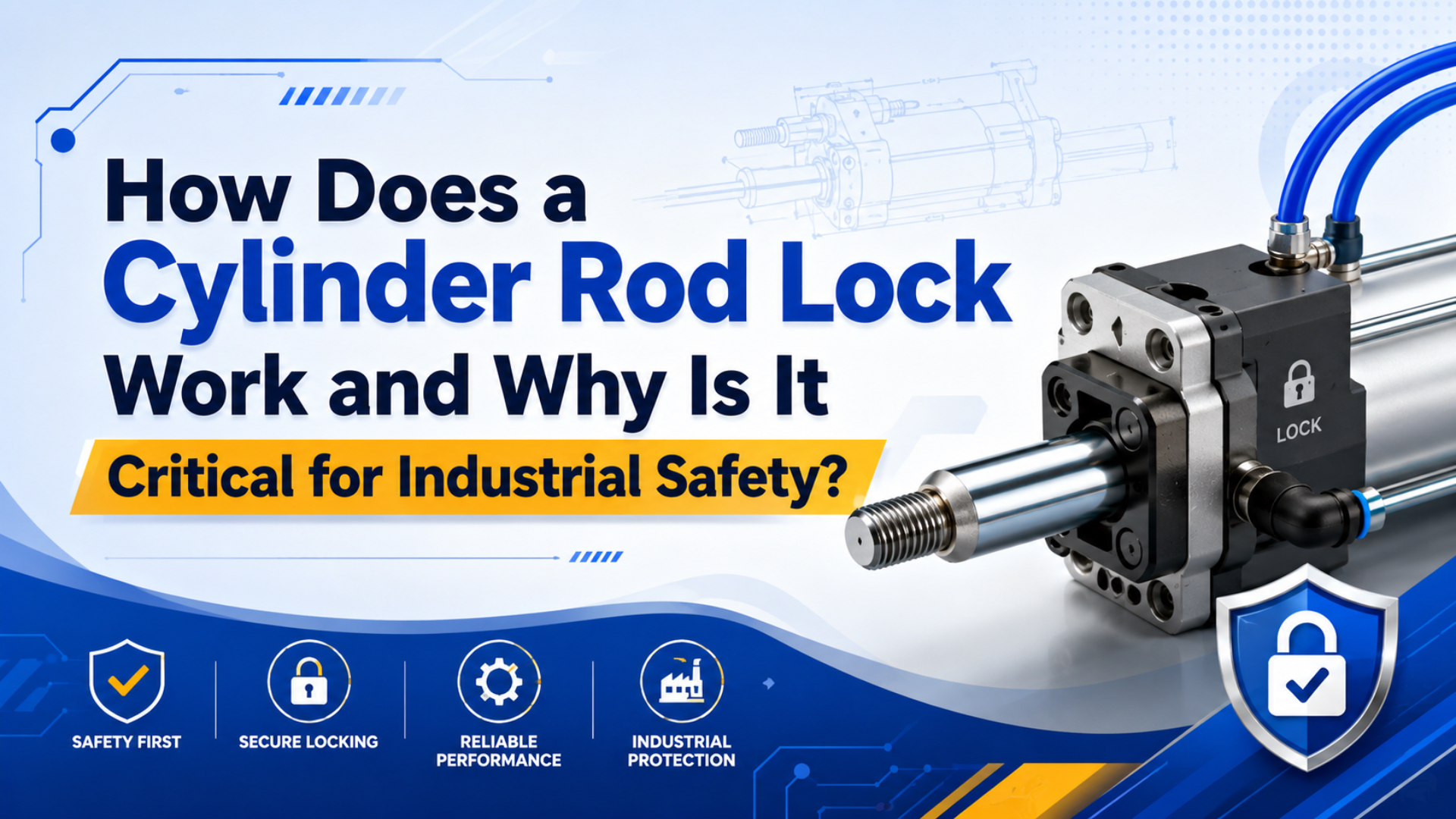
A cylinder rod lock is a mechanical holding device that clamps the piston rod when the release air disappears. It matters because the U.S. Bureau of Labor Statistics recorded 5,070 fatal work injuries in 2024, including 756 contact incidents and 844 falls, slips, and trips (BLS CFOI, 2026; BLS Table A-1, 2026).
If a vertical pneumatic axis is holding a fixture, door, guard, press platen, or lifted part, stored air alone is a weak safety argument. Air leaks. Valves shift. Tubes break. Regulators sag. A rod lock gives the machine a separate mechanical state: the rod is either free to move or physically clamped.
Cylinder rod locks are spring-engaged, air-released devices that grip a pneumatic cylinder rod after pressure loss, helping prevent drift, unintended motion, and dropped loads. They don’t replace risk assessment, guarding, or lockout/tagout. They do give the actuator a positive mechanical hold when compressed air can no longer be trusted.
Key Takeaways
- BLS counted 756 fatal contact incidents in 2024, so vertical load-holding deserves mechanical review, not guesswork.
- A typical pneumatic rod lock is spring-engaged and air-released, then clamps automatically when pressure is lost.
- Size the lock from worst-case load, direction, speed, rod diameter, release pressure, and the machine safety function.
The practical mistake is treating a rod lock as a stronger valve. It isn’t. A valve manages air. A rod lock manages the rod. Once you separate those jobs, the safety design becomes easier to audit and easier to explain to maintenance teams.
What does a cylinder rod lock do when air pressure is lost?
A cylinder rod lock answers one problem: hold the rod after release pressure disappears. Hennig’s AMLOK RLI pneumatic rod lock lists spring-engaged, pneumatic-released operation, about 100 ms response time, and 200 to 2,450 lbf holding force across its ISO 15552 range (Hennig, 2026).
In normal operation, air pressure keeps the internal lock released. The cylinder extends and retracts like a standard pneumatic actuator. When the release signal drops, springs drive the clamping mechanism into the rod, and the lock changes from an air-controlled device to a mechanical connection.
That sequence is why rod locks are often described as fail-safe. The safe condition depends on stored spring force, not on continued air pressure. What happens if the main air line breaks? The lock should engage instead of waiting for a controller to recover.
The lock can be wedge, collet, brake-style, or integrated into a cylinder package. The exact contact geometry changes by manufacturer, but the safety question stays the same: can the device hold the rod under the worst load case without damaging the rod or releasing unexpectedly?
Why is a rod lock different from a check valve or closed-center valve?
OSHA says pneumatic, hydraulic, mechanical, electrical, chemical, and thermal sources can all become hazardous energy during servicing and maintenance; its lockout/tagout standard is written to prevent unexpected energization or release of stored energy (OSHA, 2026). A rod lock is different because it physically restrains the rod.
A pilot-operated check valve can trap air in a cylinder port. A closed-center valve can block flow. Both can help position holding in some circuits. Neither creates the same direct mechanical grip on the rod, and both remain vulnerable to leakage, seal bypass, thermal pressure changes, and circuit mistakes.
The difference matters most when gravity is involved. A vertical cylinder can look stable while compressed air remains in both chambers. If a seal leaks or a tube vents, the load may move. A rod lock gives the design a second question to answer: even if pressure is gone, is the rod still clamped?
In our experience, the early warning sign is a maintenance note that says “axis slowly creeps down overnight.” That is not only a nuisance. It tells you the pneumatic circuit is already depending on trapped air, seal friction, or valve sealing to do a job that should probably be reviewed mechanically.
That doesn’t mean every cylinder needs a rod lock. Horizontal pushers, low-energy stops, and guarded transfer motions may only need normal pneumatic controls. But for raised masses, overhead gates, press tooling, vertical slides, and personnel access zones, a valve-only hold deserves a hard second look.
Where are cylinder rod locks most critical?
BLS recorded 353 manufacturing fatalities in 2024, including 104 contact incidents and 52 falls, slips, and trips in manufacturing alone (BLS Table A-1, 2026). That risk profile is why rod locks are most critical where a pneumatic failure can drop, crush, trap, or unexpectedly release a load.
Start with vertical or inclined axes. Lift tables, inspection doors, vertical clamps, raised fixtures, furnace doors, machine guards, transfer nests, and press-adjacent stops all deserve review. If gravity helps the load move after air loss, don’t treat the cylinder as self-holding.
Next, look at people. Does an operator reach below the load? Can maintenance enter the envelope? Could a dropped part block an exit or pin a fixture? Those questions matter more than cylinder bore size. A small actuator in the wrong place can still injure someone.
Hazardous material applications add another layer. If a cylinder opens a chemical gate, food-process hatch, clean-room door, or waste-system valve, a dropped or drifting actuator can become a containment issue. In those cases, the rod lock is not just about the machine. It helps protect the process boundary.
Sizing a Cylinder Rod Lock Safely
The published holding-force range for one ISO 15552 pneumatic rod-lock family is 200 to 2,450 lbf, while the same page lists about 100 ms response time (Hennig, 2026). Safe sizing starts by proving the selected lock exceeds the real load, not the average load.
Use the worst credible case. Include the load, tooling, fixture, product, friction direction, cylinder orientation, acceleration, shock, and any pressure force acting with gravity. If the cylinder can push in the same direction as the load while the lock is engaged, include that force too.
Required holding force =
  static load
+ cylinder force in the hazardous direction
+ dynamic allowance
+ safety margin from the risk assessment
What margin is enough? It depends on the machine, applicable standard, and manufacturer rating method. A purchasing rule such as “double the load” is not a safety validation. For personnel exposure, the risk assessment must define the required performance level, diagnostic coverage, and test interval.
Match the lock to the rod diameter and rod surface, not only to the cylinder bore. A clamp that fits a nominal bore series may still reject a special rod, coating, scraper, stainless option, or nonstandard tolerance. Ask the supplier to confirm rod material, hardness, surface finish, and whether the device marks the rod during engagement.
What installation details decide whether the lock actually works?
ISO 4414:2010 is the current ISO pneumatic-fluid-power safety standard, confirmed in 2021, and covers design, construction, modification, assembly, installation, adjustment, maintenance, and reliable operation of pneumatic systems (ISO, 2026). Rod-lock installation should be documented as part of that pneumatic safety design.
The lock has to be aligned with the rod. Side load is the quiet failure maker. If the lock body is cocked, the rod can wear, stick, or clamp unevenly. If the mount flexes, the holding force you bought on paper may not survive a real stop.
Use a release valve and plumbing arrangement that vents the lock quickly when the safety function demands engagement. Long tubing, small fittings, clogged silencers, and shared manifolds can all slow the pressure drop at the lock. Does the lock really see the same loss of pressure that the risk assessment assumes?
The mounting hardware also matters. A rod lock that can hold the rod still needs a structure that can hold the load. Check bolt grade, thread engagement, bracket stiffness, stop faces, and machine-frame load paths. A compact clamp on a weak bracket is a false sense of security.
For safety-related use, add status feedback where the risk assessment calls for it. A switch that confirms “lock engaged” or “lock released” can prevent restart with the lock half engaged. It also gives maintenance a useful fault signal instead of another mysterious axis alarm.
Testing and Maintenance Requirements
OSHA 29 CFR 1910.147 requires employers to use procedures that prevent unexpected energization, startup, or release of stored energy during servicing and maintenance (OSHA 1910.147, 2026). Rod-lock testing should prove the machine reaches a controlled, mechanically held state before anyone trusts it.
Test in layers. First, verify no-load engagement and release. Then test with representative load. Finally, validate the hazardous case under the conditions allowed by your safety procedure. Keep people out of the danger zone during testing, because that is exactly when bad assumptions show themselves.
I like a simple commissioning record:
| Test item | What to record | Why it matters |
|---|---|---|
| Release pressure | Pressure at which the lock fully opens | Prevents dragging or rod scoring |
| Engagement time | Time from signal loss to clamp state | Confirms stop-distance assumptions |
| Holding test | Load, direction, duration, and result | Proves the selected rating in context |
| Feedback state | Sensor status during engage and release | Prevents false restart logic |
| Manual release | Procedure, tool, and access control | Avoids unsafe recovery improvisation |
Maintenance should look for rod scoring, air leaks, slow engagement, contaminated exhaust paths, loose mounts, and inconsistent feedback. A lock that only works when it is clean, warm, and recently adjusted is not a reliable safety control.
Field check: if the cylinder drifts before the lock engages, document the drift distance and load. That measurement is often more useful than a generic response-time number, because it captures tubing volume, valve exhaust, load direction, and real machine friction in one test.
What should you include in an RFQ for a cylinder rod lock?
ISO 13849-1:2023 covers methodology for safety-related control-system parts in high-demand and continuous modes, including pneumatic and mechanical technologies (ISO 13849-1, 2026). A good RFQ should tell the supplier whether the rod lock is for positioning, drift prevention, or a safety function.
Send the cylinder bore, rod diameter, stroke, mounting style, operating pressure, release pressure, load weight, load direction, speed, environment, cycle rate, and required feedback. Add drawings if the lock must fit between an existing cylinder cap and a tight machine frame.
Be plain about the hazard. “Vertical door over operator access” is better than “need rod lock for 63 mm cylinder.” Suppliers can only help if they know whether the device is holding a fixture during production, stopping drift during inspection, or supporting a safety-rated access function.
Ask these questions before you buy:
- Is the lock spring-engaged and air-released?
- What is the rated holding force for my exact rod size?
- Is the rating static holding, emergency stopping, or braking?
- What release pressure and air volume are required?
- What rod material, hardness, and finish are acceptable?
- Are lock-engaged and lock-released sensors available?
- What manual release method exists, and how is it protected?
- Does the manufacturer approve this use when personal injury is possible?
That last question is uncomfortable. Ask it anyway. Some rod locks are sold for position holding, not personnel safety. Hennig’s RLI page, for example, specifically directs users toward other safety-device options when personal injury potential exists (Hennig, 2026).
What are common mistakes when applying rod locks?
OSHA’s lockout/tagout fact sheet says compliance with the hazardous-energy standard prevents an estimated 120 fatalities and 50,000 injuries each year in U.S. workplaces (OSHA Fact Sheet, 2023). The common mistake is assuming a component can replace a written energy-control method.
The second mistake is using a rod lock as a brake. Many rod locks are designed to hold a stopped rod, not repeatedly decelerate a moving mass. If the application requires braking, emergency stopping, or high-speed capture, get written confirmation from the supplier and validate heat, wear, and stopping distance.
The third mistake is ignoring restart. A machine can be safe when pressure is lost and unsafe when air returns. If the lock releases before the cylinder chambers are balanced, the load can jump. Sequence the restart so pressure, command state, lock feedback, and operator position all make sense.
Finally, don’t hide the manual release. It should be accessible to authorized staff and controlled by procedure. It should not invite someone to stand under the load with a wrench because production is waiting.
FAQs About Cylinder Rod Locks
The latest BLS CFOI release says a U.S. worker died every 104 minutes from a work-related injury in 2024 (BLS CFOI, 2026). These FAQ answers focus on when a rod lock materially changes pneumatic cylinder risk, not on catalog selection alone.
How does a cylinder rod lock work?
A cylinder rod lock uses spring force to clamp the piston rod when release air is removed. During normal running, compressed air holds the lock open. When pressure is lost, the springs engage the locking elements so the rod is physically restrained instead of depending on trapped air.
Is a rod lock the same as lockout/tagout?
No. A rod lock is a machine component. Lockout/tagout is an energy-control procedure required for servicing and maintenance when unexpected energy release could injure workers. A rod lock may support a safer machine state, but it doesn’t replace OSHA 29 CFR 1910.147 procedures, training, or verification.
Can a rod lock hold a vertical load after air failure?
Yes, if the lock is rated for the rod size, load direction, dynamic conditions, and safety function. The rating must exceed the worst-case load. Don’t rely on static product weight alone, because cylinder force, acceleration, shock, and mounting deflection can all raise the actual demand.
Do rod locks work in both directions?
Some rod locks hold in both directions, and some are application-limited. Confirm directionality with the manufacturer. A vertical lift, suspended load, or bidirectional actuator may need different hardware than a simple drift-prevention clamp on a horizontal cylinder.
How often should a rod lock be tested?
Use the test interval from the machine risk assessment, supplier instructions, and site safety procedure. At minimum, commissioning should record engagement, release, holding, feedback, and manual-release behavior. For safety-related applications, periodic proof testing should verify the same conditions that protect workers.
Final selection advice
BLS reviewed more than 25,500 source documents to verify 2024 fatal occupational injury data (BLS CFOI, 2026). Bring the same evidence mindset to rod locks: document the hazard, prove the load case, verify the installation, and test the safety state before production depends on it.
A cylinder rod lock is most valuable when a pneumatic actuator must hold position after pressure loss. It is least valuable when it becomes a catalog checkbox with no load calculation, no feedback, no test record, and no recovery procedure.
So ask the blunt question: if the air disappears right now, what physically stops the load? If the answer is “the rod lock, tested at this load, in this direction, with this feedback,” the design is becoming defensible. If the answer is “the valve should hold,” keep working.
Related internal resources for this topic include pneumatic cylinder basics, pneumatic cylinder sizing, solenoid valve selection, air preparation units, pneumatic cylinders, and engineering RFQ support.
Sources
- U.S. Bureau of Labor Statistics, “National Census of Fatal Occupational Injuries in 2024”, 2026. https://www.bls.gov/news.release/pdf/cfoi.pdf
- U.S. Bureau of Labor Statistics, “Table A-1. Fatal occupational injuries by industry and event or exposure, all United States, 2024”, 2026. https://www.bls.gov/iif/fatal-injuries-tables/fatal-occupational-injuries-table-a-1-2024.htm
- OSHA, “Control of Hazardous Energy (Lockout/Tagout)”, 2026. https://www.osha.gov/control-hazardous-energy/
- OSHA, “29 CFR 1910.147 - The control of hazardous energy (lockout/tagout)”, 2026. https://www.osha.gov/laws-regs/regulations/standardnumber/1910/1910.147
- OSHA, “Lockout/Tagout Fact Sheet”, 2023. https://www.osha.gov/sites/default/files/publications/OSHAFS3529.pdf
- ISO, “ISO 4414:2010 Pneumatic fluid power - General rules and safety requirements for systems and their components”, 2026. https://www.iso.org/standard/44790.html
- ISO, “ISO 13849-1:2023 Safety of machinery - Safety-related parts of control systems”, 2026. https://www.iso.org/standard/73481.html
- Hennig, “RLI Pneumatic Rod Lock (ISO 15552 Metric)”, 2026. https://hennigworldwide.com/amlok-rli
- Enfield Technologies, “S2 Rod Lock Cylinder Positioning”, 2026. https://www.enfieldtech.com/portfolio/Position/position-control-with-rod-lock-cylinder