

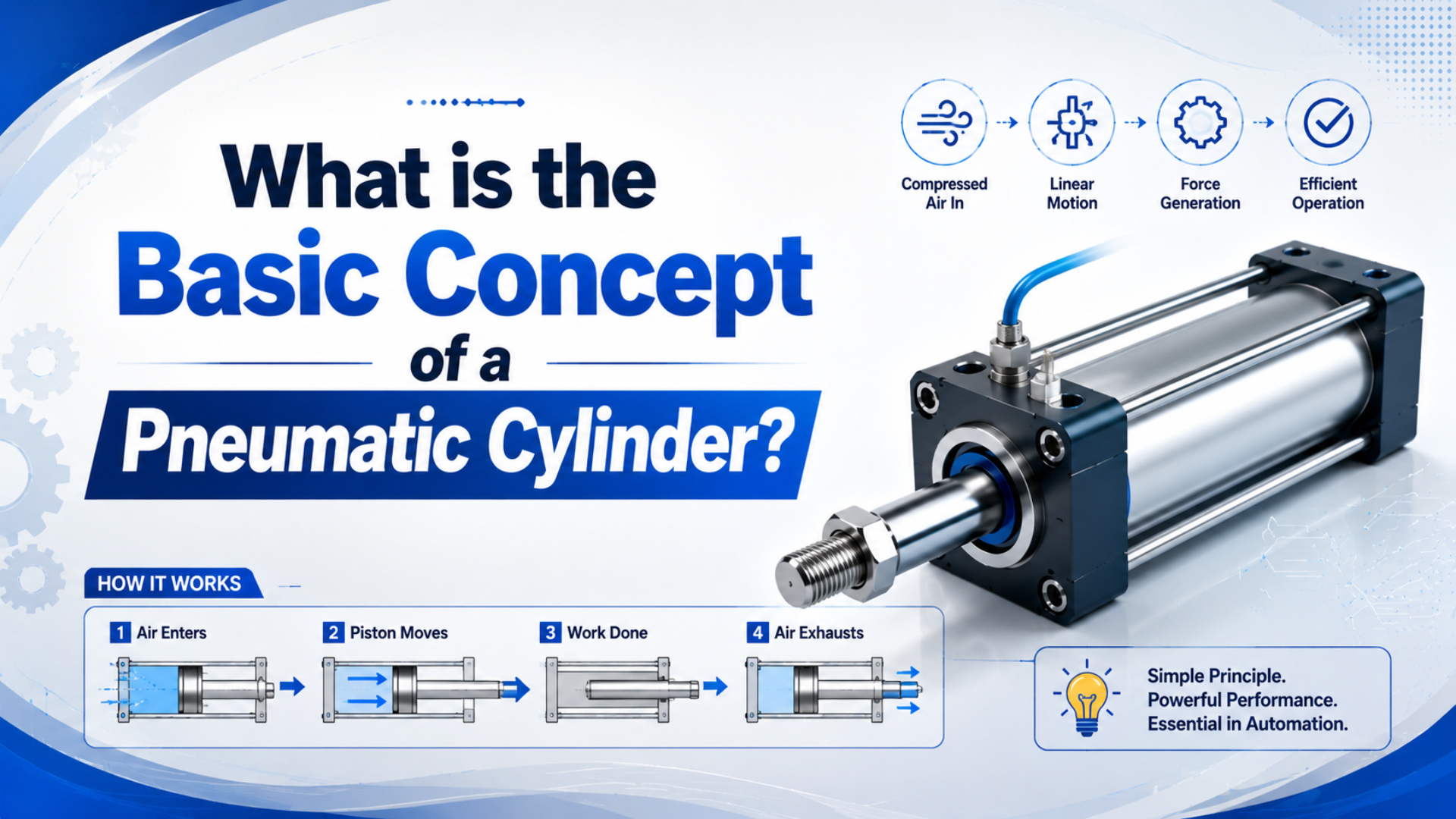
At its most basic, a pneumatic cylinder uses compressed air on a piston area to create straight-line force. Cylinder body geometry guides that motion, the rod or carriage transfers it, and valves decide which chamber receives air.
That is the classroom answer. Factory reality is richer. In practice, a pneumatic cylinder only works well when bore, stroke, pressure, valve flow, mounting, load direction, cushioning, and environment all match the application.
Key Takeaways
- NASA describes pressure force as pressure times area, which is the force logic behind pneumatic cylinder sizing.
- Parker lists ISO 15552 P1F-T cylinders in 32-125 mm bores, with extend force from 483 to 7363 N at 6 bar.
- Single-acting, double-acting, guided, compact, and rodless cylinders solve different load, space, and control problems.
What Is the Basic Concept of a Pneumatic Cylinder?
In basic terms, a pneumatic cylinder is a linear actuator that uses compressed air to create motion; NASA states that pressure force equals pressure times surface area, and the piston face is the working area in a cylinder (NASA Glenn, 2026). Conceptually, it is pressure, area, force, and guided motion.
Think of the cylinder as an air-powered translator. Air circuit pressure enters the active chamber. Piston area receives that pressure. Rod, carriage, or guided slide sends the force to a load. Valve position decides direction. Exhaust path controls how fast the opposite chamber empties.
The working sequence is:
compressed air -> cylinder chamber -> piston area -> force -> linear motionThat sequence stays true for most air cylinders. Geometry changes the details. Single-rod cylinders have different push and pull areas. Rodless cylinders move a carriage instead of a rod. Guided cylinders add rails so the cylinder does not carry side load alone.
The word “basic” can hide the real selection problem. Principle is easy, but load path decides whether the cylinder survives. Pressure creates force; mounting and guidance decide where that force goes.
How Does a Pneumatic Cylinder Work?
Pneumatic cylinders work by filling one chamber with compressed air while the opposite side exhausts; AutomationDirect explains that cylinder force is based on required force and available pressure, with bore size selected from that relationship (AutomationDirect video, 2026). Direction comes from valve switching.
In extension, air enters the cap-end chamber and pushes the piston toward the rod end. The rod extends and moves the machine element. In retraction, air enters the rod-end chamber and the cap-end chamber exhausts. On a double-acting cylinder, air powers both directions.
Speed is not only pressure. It depends on flow rate, valve size, port size, tubing length, exhaust restriction, load, lubrication, and cushioning. Enough theoretical force can still produce slow motion if the air path cannot fill and exhaust the chambers.
Main Components of a Pneumatic Cylinder
Standard pneumatic cylinders share a barrel, piston, rod, seals, end caps, ports, and mounting interfaces; Parker’s P1F-T ISO 15552 product range lists 32-125 mm bores and operating force values at 6 bar (Parker P1F-T, 2026). Each part has a different job in pressure containment and load transfer.
The barrel contains the air pressure and guides the piston. End caps close the cylinder and provide port connections. The piston separates the chambers, carries the piston seal, and receives air pressure. The rod transfers force outside the body.
Seals do the quiet work. Piston seals separate the chambers. Rod seals hold pressure around the moving rod. Wipers keep contamination from entering the cylinder. Wear bands or guide rings help keep the piston from scraping the barrel.
Mounting hardware decides how the cylinder reacts to load. Clevis mounts let the cylinder pivot. Flanges create fixed face mounts. Foot mounts sit on a base. Trunnions handle pivoting around a side axis. Wrong mounting can bend rods even when force math is correct.
| Component | Main role | Common failure clue |
|---|---|---|
| Barrel | Contains pressure and guides piston travel | Scoring, corrosion, internal leakage |
| Piston and seal | Converts pressure into force | Weak motion, bypass leakage, drifting |
| Rod and rod seal | Transfers force and holds pressure at the rod end | Oil mist, air leak, scratched rod |
| Ports and cushions | Control air entry, exhaust, and end-of-stroke impact | Slow motion, hard impact, unstable speed |
What Types of Pneumatic Cylinders Exist?
Pneumatic cylinder types are usually grouped by actuation method and load support; AutomationDirect notes that double-acting cylinders use air for both extend and retract, while single-acting spring cylinders have return-force limits (AutomationDirect Library, 2016). The right type depends on control, space, and load direction.
Single-acting cylinders use air in one direction and a spring or external load for return. These suit simple push, clamp, or release tasks, but spring force changes during travel and limits the return stroke.
Double-acting cylinders use air in both directions. This is the default choice when the machine needs powered extension and retraction, better speed control, or repeatable movement under load.
Rodless cylinders move a carriage along the cylinder body instead of extending a rod. Long-stroke layouts often benefit because a rod would need too much clearance. Selection checks shift toward carriage load, guide moment, coupling style, and sealing strip protection.
Guided cylinders and slide units add external or integrated guidance. Use them when the load applies side force, twisting moment, or offset weight. A standard round cylinder should not be used as a linear guide.
Compact cylinders reduce body length. Stainless or special-environment cylinders handle washdown, corrosion, heat, or cleanliness requirements. These options should come from catalog ratings, not guesswork.
How Do You Calculate Cylinder Force and Speed?
Cylinder force starts with F = P x A; NASA gives pressure force as pressure times area, and AutomationDirect recommends adding 25% force margin to account for friction, pressure drop, and related losses (NASA Glenn, 2026; AutomationDirect, 2026). Speed starts with air flow and chamber volume.
Use these metric shortcuts carefully:
1 bar = 0.1 N/mm2
Piston area = pi*bore^2/4
Theoretical force = pressure x effective area
At 6 bar, a 32 mm bore has about 804 mm2 piston area, so theoretical extension force is about 482 N before losses. Parker’s P1F-T data lists 483 N extend stroke force at 6 bar for the 32 mm bore, which is the same order of calculation (Parker P1F-T, 2026).
Speed is a volume problem. A larger bore or longer stroke needs more air per cycle. A valve, fitting, muffler, or tube that is too small can starve the cylinder even when the regulator reads enough pressure at rest.
When a cylinder “has no power,” I check pressure during motion before changing bore size. A blocked muffler or undersized valve can make a correctly sized cylinder behave like the bore is too small.
Where Are Pneumatic Cylinders Used?
Pneumatic cylinders are common in manufacturing because they provide simple linear motion; OSHA’s machine-guarding guidance also reminds designers that moving machine parts and functions need safeguarding when they can injure operators (OSHA, 2026). Applications should be selected with motion, force, and safety together.
Typical uses include clamping, pushing, lifting, indexing, ejecting, sorting, stopping, pressing, and opening machine guards or doors. In packaging, cylinders move guides, pushers, cutters, and seal jaws. In assembly, they position parts, clamp fixtures, and eject finished pieces.
Process equipment uses cylinders for valve actuation and repeatable mechanical movement. Food, washdown, clean-room, and corrosive environments need catalog-rated materials and seals. Do not treat “stainless” or “food grade” as a blanket answer without checking the actual specification.
Pneumatic cylinders are not the best answer for every axis. Electric actuators fit motion that needs many programmable stops, high-position feedback, quiet operation, or fine velocity profiles. Hydraulics fit cases where force density is the main problem.
What Should You Check Before Selecting a Pneumatic Cylinder?
AutomationDirect’s sizing guidance begins with required force and available air pressure, then applies extra margin for losses; Parker catalogs add bore, stroke, pressure, cushioning, and mounting data (AutomationDirect, 2026; Parker P1F catalog, 2024). A clean RFQ needs both calculation inputs and machine context.
Send the load force, moving mass, stroke, available pressure during motion, cycle rate, desired speed, mounting orientation, valve type, tubing size, and stop method. If the load is offset from the rod centerline, include the distance and direction.
Also send environment details. Dust, weld spatter, washdown, oil mist, low temperature, high temperature, food contact, and corrosive chemicals can change seal, rod, barrel, and mounting choices.
For replacement work, photos help. Send the current model number, bore, stroke, mounting style, sensor type, port position, rod end, and failure symptoms. A correct replacement is not only the same bore and stroke.
My quick triage order is force, stroke, pressure under motion, load direction, and stop method. Those five details usually reveal whether the problem is bore size, air supply, side load, or impact energy.
Conclusion
A pneumatic cylinder converts compressed air into linear motion by applying pressure to a piston area; Parker’s 32 mm ISO cylinder force value of 483 N at 6 bar is a practical example of that concept (Parker P1F-T, 2026). The basic idea is simple, but reliable selection is not only formula work.
Start with the concept: pressure acts on area and creates force. Then add the machine reality: flow controls speed, mounting controls load path, seals control leakage, and environment controls material choices.
If you keep those layers separate, pneumatic cylinders become easier to size, explain, troubleshoot, and replace. If you collapse them into one “air cylinder” guess, the machine will eventually teach the lesson at the worst possible time.
FAQs About Pneumatic Cylinders
Pneumatic cylinder questions usually start with one formula and then branch into type, speed, mounting, and safety; NASA, AutomationDirect, Parker, and OSHA each cover one part of that selection picture (NASA Glenn, 2026; AutomationDirect, 2016; Parker, 2026; OSHA, 2026). These short answers keep the concept grounded.
What is a pneumatic cylinder?
A pneumatic cylinder is an actuator that uses compressed air to create linear motion. Air pressure acts on a piston area inside the cylinder. That force moves a rod, carriage, or guided slide so the machine can clamp, push, lift, index, eject, or position a load.
How does a pneumatic cylinder create force?
The basic force relationship is F = P x A: pressure times effective piston area. NASA describes pressure force as pressure multiplied by area. In a cylinder, the active piston face is the area. Real usable force is lower after friction, pressure drop, and load effects.
What is the difference between single-acting and double-acting cylinders?
A single-acting cylinder uses compressed air in one direction and a spring or external load for return. A double-acting cylinder uses compressed air for both extension and retraction. Double-acting designs usually provide better control, but they use air in both directions.
Why is bore size important?
Bore size sets piston area, and piston area determines theoretical force at a given pressure. A 32 mm bore at 6 bar gives about 483 N theoretical extension force in Parker’s ISO 15552 P1F-T range. Larger bores increase force and air consumption at the same time.
What controls pneumatic cylinder speed?
Cylinder speed depends on air flow, chamber volume, load, exhaust restriction, valve capacity, tubing size, port size, mufflers, and cushioning. More pressure can help force, but it does not solve every speed problem. A restricted exhaust or small valve can still slow the cylinder.
When should I use a rodless cylinder?
Use a rodless cylinder when the stroke is long or the machine does not have room for an extending rod. Rodless designs move a carriage along the cylinder body. They still need load, guide moment, coupling, sealing, speed, and stop-energy checks before selection.
Sources
-
NASA Glenn Research Center: Air Pressure, pressure force relationship used to explain pneumatic cylinder force. Retrieved 2026-06-04.
-
NASA Glenn Research Center: Aerodynamic Forces, pressure times area statement for force over a surface. Retrieved 2026-06-04.
-
AutomationDirect: How to Select a Pneumatic Cylinder, video explaining cylinder selection by force, pressure, and bore size. Retrieved 2026-06-04.
-
AutomationDirect Library: Pneumatic System Design Considerations, cylinder sizing, piston area, air pressure, single-acting and double-acting selection notes. Retrieved 2026-06-04.
-
Parker: ISO 15552 Pneumatic Cylinders, P1F-T Series, bore sizes and extend-force values at 6 bar. Retrieved 2026-06-04.
-
Parker: P1F ISO Cylinders Technical Catalogue, catalog force, bore, pressure, mounting, and cylinder specification data. Retrieved 2026-06-04.
-
OSHA: Machine Guarding eTool, General Requirements, safety context for moving machine parts and functions. Retrieved 2026-06-04.