
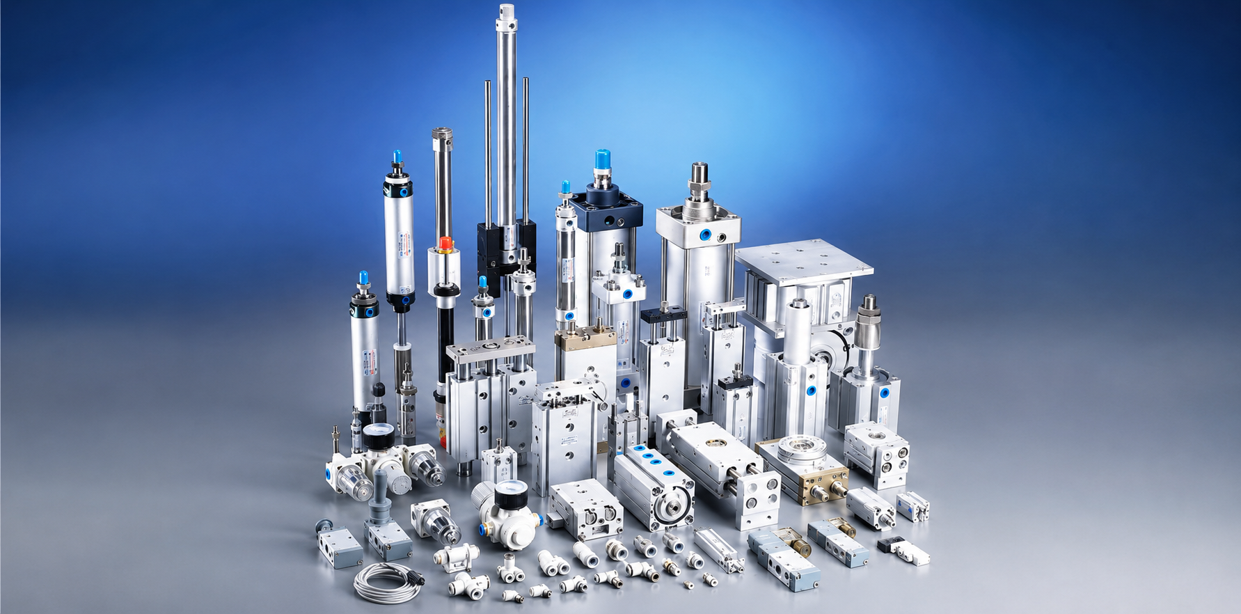
Identify the product family.
Actuator, valve, FRL unit, fitting, tubing, muffler, or replacement component.
Pneumatic FAQ & selection guide
Bepto Pneumatic is the pneumatic product line of Bepto Industrial. Use this guide to clarify cylinders, valves, FRL units, fittings, air pressure, maintenance, and troubleshooting before sending a technical inquiry.
Question topics
Choose the topic that best matches your current decision point. Each topic narrows the FAQ to the answers most useful for product selection, replacement matching, and practical maintenance review.
Pneumatics is the use of compressed air to transmit energy and create motion. In automated equipment, that air is prepared, regulated, directed by valves, and converted into linear, rotary, gripping, clamping, or blowing action by pneumatic components.
A compressor creates pressurized air, air preparation equipment removes contaminants and stabilizes pressure, valves route the air, and actuators convert air energy into machine motion. The final result depends on pressure, flow, tubing size, valve capacity, actuator size, load, and exhaust control.
Pneumatic actuation is clean, fast, simple, and cost-effective for many factory motions. Hydraulic actuation is usually chosen for very high force. Electric actuation is often selected for precise positioning, programmable motion profiles, or applications where compressed air is not available.
Pneumatic systems are widely used because they are fast, clean, overload tolerant, and straightforward to maintain. Their limits include air compressibility, lower force density than hydraulics, possible exhaust noise, leakage energy loss, and the need for clean, dry, stable compressed air.
Pneumatic datasheets often use bar, psi, kPa, and MPa. As a quick reference, 1 bar is about 14.5 psi, 100 kPa, or 0.1 MPa. Always convert pressure units before comparing cylinder force, regulator range, valve rating, or compressor output.
Pressure is the available force potential in the compressed air line. Flow is how much air volume can move through the circuit over time. Cylinder force is mainly tied to pressure and piston area, while cylinder speed is strongly affected by flow, ports, tubing, valves, and exhaust restriction.
Air consumption is the amount of compressed air a device uses during operation, usually linked to cylinder volume, pressure, cycle rate, leakage, and blow-off time. It matters because compressed air is costly to generate and undersized air supply can cause unstable motion.
Pneumatic components are common in packaging, automotive equipment, electronics assembly, food and beverage machinery, material handling, robotics, medical device production, printing, woodworking, and general machine automation where fast, repeatable motion is needed.
Common pneumatic cylinder types include single-acting, double-acting, compact, standard round body, tie-rod, guided, slide table, rodless, double-rod, gripper, stopper, and rotary actuator designs. The right type depends on force, stroke, guidance, load direction, mounting space, and repeatability.
Use a single-acting cylinder when motion is required in one powered direction and a spring or external force can return it. Use a double-acting cylinder when you need powered extension and retraction, better control in both directions, or longer strokes than spring return designs usually allow.
Cylinder force is estimated by multiplying air pressure by piston area, then allowing margin for friction, load changes, and pressure drop. For retraction on a single-rod cylinder, subtract the rod area from the piston area because the rod reduces the effective air side.
A practical cylinder selection usually includes extra margin above the calculated load because friction, acceleration, side load, pressure fluctuation, and seal drag reduce real output. The required margin depends on the machine duty, mounting, speed, vertical load risk, and available pressure.
Stroke length affects machine reach, cylinder volume, air consumption, cycle time, rod buckling risk, mounting stiffness, and guidance needs. Long strokes may require rodless cylinders, guide units, external linear guides, or intermediate support to keep motion stable.
A rodless cylinder is useful when the application needs long linear travel but does not have room for a piston rod extending outside the cylinder body. It is often used for transfer, pushing, positioning, and space-limited automation where stroke length is large compared with machine footprint.
A guided cylinder is better when the load can create side force, twisting, or poor alignment. Integrated guide rods or linear guides help resist moments, reduce rod wear, improve non-rotation, and keep the moving plate stable for pushing, lifting, stopping, or locating tasks.
A compact cylinder provides linear motion in a shorter body than many standard cylinders. It is useful in fixtures, clamp stations, small machines, and dense automation layouts where available length is limited but the application still needs simple push, pull, lift, or hold motion.
A pneumatic rotary actuator converts compressed air into limited-angle rotary motion. It is commonly used for turning parts, indexing stations, opening and closing small mechanisms, clamping, diverters, valve actuation, and compact machine motions where linkage-based rotation would be bulky.
Cylinder cushioning slows the piston near the end of stroke so the moving load does not hit the end cap harshly. It helps reduce shock, noise, vibration, seal stress, and mechanical damage, especially in higher speed or higher load applications.
Cylinder speed is usually controlled by regulating exhaust flow with meter-out flow controls, not by choosing an undersized directional valve. Valve capacity, tube size, port size, load, pressure stability, and muffler restriction all affect how smoothly the cylinder moves.
On a single-rod double-acting cylinder, the rod occupies part of the piston area on the retract side. With the same air pressure, the smaller effective area produces lower retract force than extend force, so both directions should be checked during sizing.
Many pneumatic cylinders can include a magnet inside the piston. Reed or electronic sensors mounted in the cylinder slot detect that magnetic field and send position signals to a controller. Sensor type, voltage, wiring, and mounting position must match the control system.
Side loading pushes the piston rod sideways instead of along its intended axis. This can wear bushings and seals, create stick-slip motion, increase friction, cause leakage, and shorten cylinder life. Use proper alignment, floating joints, guides, or guided cylinders when side force is expected.
Choose mounting by looking at load direction, alignment, available space, stroke, service access, and whether the cylinder must pivot. Common options include foot, flange, clevis, trunnion, direct mount, and bracket mounting. Poor mounting can create bending loads and early wear.
Useful replacement details include bore, stroke, rod diameter, mounting style, port size, thread type, body style, overall length, sensor type, cushioning, operating pressure, and photos of the nameplate and installation. Matching only the visible stroke is usually not enough.
Cylinder drift can come from internal seal leakage, valve leakage, trapped air exhausting through a worn valve, load forces exceeding holding capability, or an unsuitable circuit for vertical loads. Holding a safety-related load requires a proper mechanical or safety-rated design review.
A pneumatic solenoid valve uses an electrical coil to shift an internal valve element and control compressed air. It can start, stop, vent, or redirect air to cylinders, grippers, rotary actuators, blow-off nozzles, vacuum devices, and other pneumatic equipment.
The first number is the number of ports and the second number is the number of valve positions. A 3/2 valve has three ports and two positions. A 5/2 valve is common for double-acting cylinders, while a 5/3 valve adds a center position.
A normally closed valve blocks flow in its de-energized state and opens when actuated. A normally open valve allows flow in its de-energized state and closes when actuated. The correct choice depends on the safe default behavior of the machine.
A single-solenoid valve usually returns by spring or air pilot when power is removed. A double-solenoid valve can remain in its last shifted position until the opposite coil is energized. Choose based on control logic, safe state, cycle behavior, and machine restart requirements.
A direct acting solenoid valve shifts by coil force and can work at low or zero differential pressure, usually at smaller flow sizes. A pilot operated valve uses air pressure to assist shifting, so it can handle larger flow but needs sufficient pilot pressure and clean air.
Cv is a flow coefficient that helps compare how much flow a valve can pass under defined conditions. For pneumatic circuits, too little valve capacity can cause slow or erratic actuator motion, while excessive flow without speed control can contribute to harsh end-of-stroke impact.
Match the coil voltage and current type to the control system, such as 24 VDC, 110 VAC, or 220 VAC. Also check connector style, duty cycle, coil power, surge protection needs, environment, and whether the machine control output can drive the coil safely.
Likely causes include low voltage, incorrect coil type, insufficient pilot pressure, dirty air, blocked pilot passages, excessive pressure drop, loose electrical connections, or a valve that is not sized for the circuit. Check air supply and electrical conditions before replacing parts.
A valve manifold groups multiple valves on one base so air supply, exhaust, wiring, and maintenance are cleaner. It is useful when a machine has several actuators near each other, needs compact plumbing, or benefits from modular valve replacement.
Air must leave the opposite side of a cylinder for the piston to move. Restricted exhaust ports, small mufflers, undersized fittings, or poor tubing layout can slow the cylinder, while unrestricted exhaust can make motion too fast unless controlled by proper flow controls.
A quick exhaust valve vents cylinder air close to the actuator instead of routing all exhaust back through the directional valve. It can increase cylinder speed and reduce response time, but it should be used carefully where noise, cushioning, or controlled deceleration matters.
A pneumatic valve may fail to shift because of no electrical signal, wrong voltage, burned coil, insufficient pilot pressure, blocked exhaust, contamination, sticky seals, excessive back pressure, or poor wiring. Confirm signal, supply pressure, manual override behavior, and air quality first.
A closed center valve blocks ports in the center state, an exhaust center vents actuator ports, and a pressure center supplies pressure to actuator ports. The right center condition depends on desired stop behavior, load movement, pressure retention, and safety requirements.
The manual override lets a technician shift the valve during setup or troubleshooting without energizing the coil from the controller. It is useful for commissioning, but the machine should be in a safe state before using it because actuators may move.
An FRL unit combines filter, regulator, and lubricator functions. The filter removes particles and liquid water, the regulator stabilizes downstream pressure, and the lubricator adds oil mist only when the component design and application require lubricated air.
A pneumatic air filter removes solid particles and separates liquid water from the compressed air stream. Depending on filter type and rating, filtration can help protect valves, regulators, cylinders, fittings, and tools from wear, sticking, corrosion, and unexpected downtime.
Choose filter micron rating based on downstream component requirements, plant air quality, flow demand, and maintenance interval. General machine filtration often uses a coarse particulate filter, while precision valves, instrumentation, or special processes may need finer filtration or coalescing filtration.
Select a regulator by required pressure range, flow capacity, port size, response stability, gauge option, relieving or non-relieving behavior, and downstream demand. A regulator that is too small can create pressure drop during high flow and cause weak or inconsistent actuator motion.
No. Many modern pneumatic valves and cylinders are pre-lubricated or designed for non-lube service. Add a lubricator only when the product specification or application requires it, and avoid mixing lubrication policies because starting oil mist and later stopping it can create reliability problems.
An air dryer is needed when moisture control is important for reliability, corrosion prevention, freezing prevention, instrumentation, paint or packaging quality, or clean process requirements. Filters remove liquid water, but a dryer reduces water vapor and helps control pressure dew point.
Pressure dew point is the temperature at which water vapor in compressed air will condense at system pressure. Lower pressure dew point means drier air. It is important when lines pass through cold areas, when instruments are sensitive, or when moisture can damage components.
ISO 8573-1 classifies compressed air quality by solid particles, water, and oil content. It helps engineers specify how clean and dry air should be for a machine or process. Component selection should follow the required air quality class and site maintenance reality.
Water appears because atmospheric moisture enters the compressor intake and condenses as air cools in the receiver, piping, and downstream equipment. Check compressor aftercooling, receiver drains, filter drains, dryer performance, piping slope, and whether the air demand exceeds treatment capacity.
Drain frequency depends on humidity, compressor runtime, air demand, receiver size, dryer condition, and filter location. Manual drains need routine checks, while automatic drains reduce missed maintenance. Never allow bowls or receivers to stay full of condensate during production.
Pressure drop can come from undersized tubing, long pipe runs, clogged filters, restricted fittings, small valves, blocked mufflers, excessive simultaneous demand, leaks, or regulators set too close to required working pressure. Measure pressure at the machine while it is cycling.
A pressure relief valve helps protect equipment by venting excess pressure when upstream pressure rises above a set value. It is part of over-pressure protection, but final safety selection should follow applicable standards, component ratings, and the machine risk assessment.
A pneumatic lockout valve is used to isolate and exhaust compressed air during service so stored pneumatic energy can be controlled. It supports lockout procedures, but machine safety depends on the full circuit, residual pressure release, vertical load control, and site procedures.
Oil-free air means oil carryover is controlled to a level required by the process or component. It does not mean the air is automatically dry or particle-free. Oil-free applications still need filtration, drying, materials review, and careful lubricant policy for downstream components.
Air quality depends on whether the air contacts product, packaging, or only machine actuators. Food, packaging, electronics, and clean processes may require stricter particle, water, and oil control. Confirm process requirements, applicable standards, and component material compatibility before selecting equipment.
Regulator creep can be caused by seat contamination, worn seals, incorrect installation, damaged valve parts, or demand conditions outside the regulator range. Isolate the downstream circuit, check gauge accuracy, inspect air cleanliness, and replace the regulator if it cannot hold stable pressure.
Choose fittings and tubing by tube outside diameter, thread type, pressure rating, temperature range, flow demand, bend radius, material compatibility, vibration, washdown exposure, and installation space. Also check whether the circuit needs push-in, threaded, barb, metal, plastic, or stainless fittings.
A push-in fitting grips the tube with a collet or gripping ring and seals around the tube with an internal O-ring. The tube must be cut square, inserted fully, and matched to the correct outside diameter to prevent leaks or tube pullout.
Most push-in pneumatic fittings are selected by tube outside diameter, such as 4 mm, 6 mm, 8 mm, 10 mm, or 1/4 inch OD. Hose barb and some flexible hose applications may use inside diameter, so confirm the connection style before ordering.
G threads are parallel BSPP threads that normally seal with a face seal or O-ring. R and NPT threads are tapered pipe threads that seal through thread engagement and sealant. Metric threads are common on compact components and must match pitch and sealing method.
Use sealant according to the fitting thread and manufacturer instructions. Tapered threads often require sealant, while many parallel threads seal with an O-ring or bonded washer. Keep tape fragments and excess sealant out of the air path because they can damage valves.
Common causes include wrong tube size, scratched tube surface, oval or crushed tube, angled cuts, incomplete insertion, worn O-ring, damaged collet, side load, contaminated seal, or thread leakage. Re-cut the tube square and inspect both the tube and fitting.
Polyurethane tubing is flexible and useful for moving assemblies. Nylon tubing is tougher and handles higher pressure or longer straight runs well. Polyethylene tubing is economical and chemically resistant in some applications. Final selection depends on pressure, temperature, flexibility, environment, and fitting compatibility.
A tube bent too tightly can kink, restrict flow, weaken the tube wall, or pull sideways on fittings. Respecting bend radius keeps air flow stable, reduces leaks, and prevents hidden restrictions that can make cylinders slow or valves unreliable.
Choose metal fittings when the application has higher mechanical stress, heat, vibration, threaded durability needs, or harsh handling. Stainless steel fittings may be preferred for washdown, corrosion resistance, food-related equipment, outdoor exposure, or aggressive environments when compatible with the rest of the system.
A pneumatic muffler reduces exhaust noise from valves and actuator ports. It can also reduce contamination entering open exhaust ports. Select it so exhaust flow remains adequate; a clogged or undersized muffler can slow cylinders and create back pressure.
A pneumatic speed controller restricts air flow in one direction while allowing freer flow in the opposite direction. It is commonly installed near cylinder ports to tune extension or retraction speed, especially with meter-out control for smoother actuator movement.
Depress the release collar evenly, push the tube slightly inward to unload the gripping teeth, then pull the tube straight out. If the tube end is scored or deformed, cut it back square before reinstalling, or replace the fitting if the collet is damaged.
Start at the air source and move downstream: compressor pressure, receiver, dryer, FRL, regulator setting, filter condition, leaks, tubing, fittings, valve signal, valve shifting, actuator movement, load, and exhaust path. This avoids replacing components before confirming supply conditions.
Use listening, soapy water, pressure decay checks, flow monitoring, or ultrasonic leak detection depending on plant size and noise level. Common leak points include fittings, tubing cuts, threaded ports, valve exhausts, cylinder seals, filter bowls, quick couplers, and unused branches.
Slow or weak cylinder motion can be caused by low pressure, low flow, undersized valves, small tubing, clogged filters, blocked mufflers, restricted exhaust, internal seal leakage, air leaks, excessive load, side loading, poor lubrication where required, or a sticky valve.
Simultaneous actuator demand can exceed the capacity of the regulator, tubing, valve manifold, compressor, receiver, or branch piping. Measure pressure during the actual cycle, not only at idle, and check for leaks or restrictions that only appear under flow.
Loud exhaust usually comes from fast venting through valve or actuator exhaust ports. A correctly sized muffler can reduce noise, but it must not create excessive back pressure. If noise increases suddenly, check for missing mufflers, blocked silencers, or abnormal valve behavior.
Contamination can show up as sticky valves, slow cylinder movement, seal wear, pressure instability, water in bowls, rust-colored residue, clogged mufflers, damaged O-rings, or repeat failures after replacement. Solve the air quality problem before replacing the same component again.
Replacement interval depends on air quality, filter rating, flow rate, operating hours, pressure drop, and site standards. A rising pressure drop, dirty element, water carryover, or unstable downstream pressure can indicate that service is due even before a calendar interval ends.
Freezing happens when moisture remains in compressed air and line temperature drops below the dew point. Prevention may require drying, proper drains, insulated or heated routing, avoiding low points that collect condensate, and confirming that air treatment matches the coldest operating condition.
Fix leaks, reduce pressure to the lowest practical setting, avoid inappropriate blow-off use, size valves and tubing correctly, keep filters clean, shorten unnecessary tube runs, use efficient nozzles, monitor air consumption, and turn off isolated branches when equipment is not running.
A practical checklist includes pressure readings, leak checks, filter bowl drains, regulator settings, dryer condition, tubing wear, fitting security, muffler blockage, valve response, cylinder rod condition, abnormal noise, lubrication policy, safety valve condition, and documentation of recurring faults.
End-of-stroke slamming can be caused by excessive speed, oversized flow, insufficient cushioning, heavy load inertia, missing shock absorbers, wrong flow control adjustment, quick exhaust used without deceleration, low back pressure, or a cushion needle that is opened too far.
Use clean and dry air, stay within rated pressure and temperature, avoid side loading, keep tubing supported, prevent contamination, maintain filters and drains, use compatible materials, control speed and shock, and replace worn seals or damaged fittings before failure spreads.
Send product family, quantity, application, pressure, flow or speed target, dimensions, bore and stroke if known, voltage, port thread, tube size, environment, existing model number, drawings, photos, and required documents. More context helps Bepto Pneumatic review the request faster.
Start with photos from several angles, dimensions, port and tube sizes, mounting pattern, stroke, voltage, pressure rating, material, and machine function. For cylinders, measure bore and stroke. For valves, identify port count, position count, coil voltage, and actuation method.
Match the valve to cylinder type, required direction control, flow demand, speed, pressure, voltage, port size, exhaust behavior, and safe default state. A double-acting cylinder commonly uses a 5-port directional valve, while single-acting cylinders often use a 3-port valve.
Start with the motion requirement. If the machine needs push, pull, clamp, lift, or rotate, begin with actuators. Then select valves for control, FRL equipment for air quality and pressure, fittings and tubing for routing, and accessories for sensing, noise, and speed.
Useful values include pressure conversion, cylinder force, air consumption, flow conversion, and Cv estimates. Calculator results are starting points, not final approvals, because real machines also include friction, pressure drop, acceleration, temperature, mounting, and safety requirements.
Important details include temperature, humidity, washdown, dust, oil mist, welding spatter, outdoor exposure, food-contact zones, chemicals, vibration, cleanroom requirements, and available maintenance access. These conditions influence materials, seals, lubrication, tubing, fitting style, and air preparation.
An undersized cylinder may not produce enough force, especially after pressure losses and friction. An undersized valve or tube can restrict flow, slow the actuator, create unstable motion, or require higher system pressure that increases energy use and component stress.
Consider a shock absorber when load inertia is high, speed is high, stroke-end impact remains harsh, cycle conditions change, or built-in cushioning cannot absorb enough energy. Shock absorber selection should account for moving mass, velocity, cycle rate, stroke, and mounting.
Common mistakes include ignoring pressure drop, using only port size to judge valve capacity, undersizing tubing, forgetting exhaust flow, allowing side loads on cylinders, mixing thread standards, skipping air preparation, overlooking environment, and not defining the required safe state.
Compare operating pressure, proof pressure, temperature range, flow or Cv, bore, stroke, port size, thread standard, voltage, response time, seal material, lubrication requirement, mounting options, sensor compatibility, body material, service life notes, and recommended air quality.
Compressed air is convenient and clean at the point of use, but it takes electrical energy to compress, dry, filter, distribute, and regulate it. Leaks, excessive pressure, and inappropriate blow-off use can turn a small pneumatic circuit into a major energy cost.
Clean and dry air means solid particles, liquid water, oil mist, and condensate are reduced to a level suitable for the valves, cylinders, grippers, and instruments being used. The right level depends on product design, duty cycle, environment, and any specified air quality class.
Start at the air supply, then follow air preparation, shutoff or soft-start valves, directional valves, flow controls, actuators, exhaust ports, sensors, and safety devices. Port labels and valve positions show how air moves in each machine state.
Common pneumatic valve port numbering uses 1 for pressure supply, 2 and 4 for working ports to the actuator, and 3 and 5 for exhaust. Always confirm the marking on the actual valve body because compact valves and manifolds may show labels differently.
Any unit is acceptable if the entire selection is converted consistently. Problems appear when cylinder force, regulator range, valve flow, and compressor pressure are compared in mixed units without conversion, especially between bar, MPa, and psi.
Duty cycle describes how often and how long a component operates. A slow clamp used a few times per hour has different wear, heat, air consumption, and service needs than a high-speed actuator cycling several times per second.
No. Higher pressure can increase cylinder force, but it also raises energy use, leakage loss, component stress, and impact force. The better approach is to size the actuator and flow path correctly, then run at the lowest stable pressure that meets the motion requirement.
Common search-driven problems include air leaks, slow cylinders, weak force, pressure drop, noisy exhaust, sticky solenoid valves, water in air lines, tubing popping out, wrong thread selection, and uncertainty about 3/2, 5/2, and 5/3 valve functions.
Start with the required load force, add allowance for friction and machine losses, divide by available working pressure, and choose a piston area that provides a practical margin. Then check stroke, speed, mounting, side load, cushioning, and air consumption.
Choose a stroke long enough to complete the machine motion without bottoming hard at either end. Include tooling clearance, overtravel allowance, sensor position, cushion adjustment space, and any stroke adjustment or stop mechanism required by the machine.
No. The cylinder normally needs a magnetic piston and a compatible sensor groove or mounting band. If the existing cylinder has no magnet, external limit switches, proximity sensors, or a replacement cylinder with a magnetic piston may be needed.
Pneumatic cylinder rods are meant to transmit axial force. Side load can wear the rod bearing and seals, bend the rod, cause sticking, and create leakage. Use guides, slides, external bearings, or guided cylinders when the load is not well aligned.
Yes, but vertical loads need extra attention because gravity affects extension, retraction, holding, and safe stopping. Review load weight, air loss behavior, locking needs, center valve function, speed control direction, and any requirement to prevent dropping.
Retract force is lower because the rod takes up part of the piston area on the rod side. With the same pressure, less effective area means less available retract force, so both extend and retract directions should be checked during sizing.
Adjust cushioning gradually while the machine is running at the real load and speed. The goal is smooth deceleration without slamming, bouncing, or excessive delay. If cushioning cannot absorb the energy, use lower speed or external shock absorption.
A stainless rod is useful where corrosion, washdown, chemicals, outdoor exposure, or appearance matters. Confirm the rest of the cylinder construction as well, because a stainless rod alone does not make the whole actuator washdown or chemical resistant.
Use a pneumatic gripper when the part has edges, holes, porous surfaces, rough texture, or geometry that vacuum cannot hold reliably. Vacuum cups are often better for flat sheets, cartons, panels, and parts with accessible sealing surfaces.
Possible causes include overload, impact, guide binding, contamination, insufficient lubrication where required, incorrect speed control, or a magnetic coupling that has separated after a blockage. Depressurize and follow the manufacturer's reset procedure before restarting.
A 3/2 valve has three ports and two positions, often for single-acting cylinders or air signals. A 5/2 valve controls double-acting cylinders with two positions. A 5/3 valve adds a center position for blocked, exhausted, or pressurized center behavior.
No. Port size is only one clue. Compare flow capacity, Cv or effective area, pressure range, response time, manifold restriction, tubing size, exhaust path, and actuator air demand. Two valves with the same port can perform very differently.
Match the coil to the machine control power and confirm AC or DC type, connector style, allowable voltage tolerance, power consumption, duty cycle, and available protection. A wrong coil voltage can prevent shifting or damage the coil.
A click means the coil may be energizing, but the spool may still fail to move because of low supply pressure, low voltage under load, stuck spool, contamination, blocked pilot air, incorrect manual override position, or undersized air supply.
Some warmth is normal during continuous duty, but excessive heat can come from wrong voltage, poor cooling, overvoltage, a coil rated for intermittent use, a stuck armature, incorrect frequency, or a valve that remains energized longer than intended.
Manual override lets a technician shift the valve during setup or troubleshooting without an electrical signal. It should be used carefully because it can move actuators unexpectedly, and it should be returned to the correct position before automatic operation.
A direct-acting valve uses the coil force to move the sealing element directly and can often work at very low pressure. A pilot-operated valve uses pilot pressure to move the main spool, allowing larger flow with a smaller coil but usually requiring minimum operating pressure.
Closed center can trap air, exhaust center can vent actuator ports, and pressure center can pressurize both actuator ports. The right choice depends on safe stopping, vertical load behavior, manual movement needs, and the machine risk assessment.
Exhaust leakage can come from valve spool seal wear, dirt, damaged internal seals, incorrect assembly, or internal leakage from the cylinder connected to the valve. Isolate the actuator and valve carefully to identify which component is leaking.
A DIN connector is a removable electrical plug used on many solenoid coils. It simplifies wiring and replacement, and may include LED indication or surge suppression. Confirm connector size, pin layout, voltage, and protection rating before ordering.
FRL stands for filter, regulator, and lubricator. The filter removes particles and liquid water, the regulator sets downstream pressure, and the lubricator adds oil mist only when the downstream equipment actually requires it.
The correct micron rating depends on the component and air quality requirement. General machine air may use coarser filtration, while precision valves, instruments, or clean applications may need finer filtration and oil removal. Follow the component datasheet first.
Pressure drops when air flows through restrictions such as filter elements, regulators, lubricators, small ports, clogged bowls, undersized units, or dirty elements. The drop is usually highest when machine demand and flow rate are highest.
Compressed air cools as it moves through the system, and water vapor can condense into liquid. A filter bowl catching water means moisture is present upstream; check compressor aftercooling, receiver drains, dryer performance, pipe slope, and local point-of-use drains.
A refrigerated dryer is common for general plant air where a moderate pressure dew point is acceptable. A desiccant dryer is used when much drier air is needed, such as cold environments, instruments, or processes sensitive to moisture.
Many machines benefit from a local regulator because it stabilizes the pressure seen by valves and actuators. Local regulation also lets the machine run at the lowest practical pressure instead of relying only on the plant header setting.
Yes. Over-lubrication can contaminate work areas, collect dirt, affect seals, and make downstream equipment messy. Many modern pneumatic components are designed for non-lubricated air, so add a lubricator only when the component or application requires it.
Automatic drains reduce the chance that condensate is forgotten in filters, receivers, and dryers. Manual drains can work when maintenance is disciplined, but missed draining can carry water downstream and create valve, cylinder, and fitting problems.
Push-in fittings typically use a gripping collet or claw to hold the tube and an internal seal to make the air-tight connection. The tube end must be cut square, clean, and fully inserted to seal reliably.
Polyurethane tubing is flexible and easy to route, making it common for moving or compact machine areas. Nylon tubing is usually stiffer and can be better for longer runs, higher dimensional stability, or some harsher environments. Check pressure, temperature, and chemical compatibility.
Avoid mixing sizes unless the fitting is specifically rated for both. Close-looking sizes such as 6 mm and 1/4 inch are not identical, and the wrong tube OD can leak, pull out, or damage the fitting seal and gripping mechanism.
NPT and BSPT/R are tapered pipe threads that seal differently and are not normally interchangeable. BSPP/G threads are parallel and usually need a sealing face, gasket, or O-ring. Identify the thread standard before ordering fittings or adapters.
Depressurize the line, push the release collar squarely toward the fitting body, and pull the tube straight out. If the tube end is scratched, grooved, oval, or cut at an angle, trim it square before reconnecting.
Larger tubing can reduce restriction and pressure drop, but speed also depends on valve flow, port size, exhaust path, flow controls, actuator volume, and load. Oversized tubing may waste air volume if the actuator is small or the run is long.
Tubing can degrade from UV exposure, heat, oil, chemicals, ozone, bending stress, abrasion, or age. Replace damaged tube and review material selection, routing, support, bend radius, and exposure to the surrounding process.
Use sealant only where the thread style requires it and follow the fitting manufacturer's instructions. Keep tape or paste away from the first thread and internal air path because loose sealant can travel downstream and contaminate valves.
Vacuum level describes how strong the pressure difference is, while vacuum flow describes how much air can be evacuated or handled over time. Porous products need more flow, while sealed smooth products often need less flow but a stable vacuum level.
A vacuum ejector uses compressed air through a nozzle to create a low-pressure zone that pulls air from the suction port. It is compact and easy to install, but compressed-air consumption should be reviewed for cycle time and energy cost.
Match the cup to part weight, surface texture, porosity, curvature, temperature, oil or dust exposure, available contact area, cycle speed, and safety factor. Test with real parts because surface leakage often decides success.
Common causes include worn cup lips, dirt, porous material, poor cup position, part flexing, low vacuum flow, undersized ejector, leaking tube, clogged filter, fast acceleration, or not enough safety margin for the product weight.
A vacuum switch is useful when the control system must confirm that a part was picked before moving. It can reduce mis-picks and dropped parts, but the setpoint should be tuned for the real part surface and leakage condition.
They can, but porous materials leak air through the surface, so the system often needs higher vacuum flow, larger cups, foam cups, multiple cups, or a different gripping method. Confirm with sample parts before final design.
Replace cups when lips are cut, hardened, permanently deformed, contaminated, or no longer recover shape. Loss of holding force, increased cycle rejects, and frequent vacuum alarms are signs that cup condition should be checked.
Faster release may require a blow-off pulse, shorter suction lines, smaller internal volume, a valve closer to the cup, or a dedicated ejector with release control. Avoid excessive blow-off that moves or damages the product.
A reed switch is a magnetic sensor that changes state when the cylinder piston magnet reaches its sensing position. It is simple and common, but it must match the cylinder groove, voltage, current, and PLC input requirements.
PNP sensors switch positive voltage to the PLC input, while NPN sensors switch the input toward 0V. The correct choice depends on the PLC input wiring standard used on the machine, so do not mix them without checking the control design.
Check sensor position, piston magnet, groove compatibility, wiring, voltage, PNP/NPN type, load current, cable damage, and whether the cylinder has stopped at the expected end position. Move the sensor slowly while watching the indicator LED.
A prewired cable is simple and compact. A quick connector makes replacement easier and can reduce wiring time on modular machines. Review vibration, washdown, cable flexing, connector protection rating, and spare part strategy.
Place the sensor where the piston magnet reliably triggers at the required machine position. Many end-of-stroke applications mount near the end cap, but final position should be adjusted during commissioning and verified at real speed.
Flicker can be caused by weak magnetic field, poor sensor placement, loose mounting, vibration, unstable power, electrical noise, damaged cable, wrong input type, or a piston stopping near the edge of the sensing range.
Leaks can waste a large share of compressed-air production and create pressure instability that makes machines appear undersupplied. A leak program should include detection, repair, retesting, and tracking instead of simply raising compressor pressure.
Common causes include undersized tubing, long hose runs, small quick couplers, clogged filters, undersized FRLs, restrictive valves, leaking fittings, blocked mufflers, and using components above their practical flow range.
A receiver or local reservoir helps when demand is intermittent and peak flow exceeds what the supply line can deliver momentarily. It can stabilize pressure, but it should not hide chronic leaks, undersized piping, or poor air preparation.
A soft-start valve gradually pressurizes the downstream circuit during startup instead of applying full pressure instantly. It helps reduce sudden actuator movement and shock, but it must be reviewed as part of the machine safety concept.
A dump valve removes downstream pneumatic energy by exhausting air from the machine circuit. It is often used for shutdown or safety-related functions, but the overall safety performance depends on the circuit, controls, monitoring, and risk assessment.
Yes if the cylinder still has enough force and speed margin under real load. Lowering pressure without checking bore size, friction, pressure drop, vertical loads, and cycle timing can cause slow movement or unreliable operation.
Open tubes or oversized nozzles can consume large air flow continuously. Use engineered nozzles, lower pressure, pulsed air, mechanical alternatives, or vacuum where suitable, and shut off blow-off when the machine is idle.
Usually not as the first step. Measure pressure at the machine during the actual cycle, then check restrictions, leaks, filters, regulators, tubing, valves, and local storage. Raising plant pressure can increase energy use across every leak and open demand.
Washdown applications may need corrosion-resistant materials, sealed sensors, suitable tubing, protective covers, water-resistant cylinders, and compatible seals. Confirm cleaning chemicals, spray direction, temperature, pressure, and any food-contact requirements.
Only within their rated temperature range. High heat can harden seals, weaken tubing, damage sensors, and shorten lubrication life. Use high-temperature seals, metal fittings, remote valves, shielding, or cooler mounting locations when needed.
Review flame-resistant or spatter-resistant tubing, metal fittings, protective covers, routing away from sparks, and shields. Standard polyurethane tubing can be damaged by hot spatter, causing leaks or sudden tube failure.
Cleanroom applications may require low particle generation, compatible lubricants or lubrication-free components, controlled exhaust, clean tubing, suitable materials, and air quality documentation. Exhaust air and component wear particles should be reviewed early.
They can be used outdoors if the selected components handle temperature, UV, rain, dust, corrosion, freezing moisture, and enclosure needs. Protect regulators, sensors, coils, and tubing from weather and drain water before freezing conditions.
Chemicals can swell, soften, crack, or embrittle tubing and seals. Identify the exact chemical, concentration, temperature, exposure time, and cleaning method, then select compatible tube, seal, body, and fitting materials.
Start with audible inspection and soap solution for accessible joints, then use ultrasonic leak detection for noisy plants or hidden leaks. Check fittings, tube cuts, valve exhausts, cylinder seals, regulators, drain valves, and unused ports.
Valves can stick from dried lubricant, contamination, corrosion, swollen seals, water carryover, or spool deposits. Clean dry air, correct materials, periodic operation, and replacing damaged seals help prevent repeat sticking.
Cycle drift can come from changing supply pressure, warming components, clogged filters, condensation, leaks, load variation, regulator creep, valve response changes, or exhaust mufflers becoming restricted during operation.
Useful spares often include common tube sizes, push-in fittings, mufflers, filter elements, drain parts, solenoid coils, connectors, cylinder sensors, seal kits, flow controls, and the most common cylinders or valves used on critical machines.
Bepto Pneumatic can review old model numbers, photos, dimensions, port sizes, mounting details, and application notes to suggest a practical replacement option. Exact interchange should be confirmed against datasheets and installation constraints.
The best RFQs include product family, model or drawing, quantity, pressure, voltage, port thread, tube OD, material preference, environment, delivery location, target date, and whether datasheets, CAD files, samples, or certificates are needed.
Common document requests include datasheets, dimensional drawings, CAD files, material notes, RoHS or REACH declarations where applicable, operating instructions, packing details, and product photos for approval before bulk purchase.
Ask for review when the machine has high speed, heavy loads, vertical motion, safety concerns, harsh environment, repeated failures, air consumption problems, uncertain thread standards, missing model numbers, or several components that must work together.
Try a broader keyword, switch to all questions, or send the application details for review.
From answer to action
Actuator, valve, FRL unit, fitting, tubing, muffler, or replacement component.
Pressure, flow, bore, stroke, voltage, port thread, tube size, environment, model number, or drawing.
Bepto Pneumatic can connect the question to product selection, replacement matching, documents, or quotation follow-up.
Source notes
Primary references for pneumatic safety, compressed-air quality, and cleaning questions.
Still choosing?
You do not need a perfect model number to start. A photo, drawing, pressure value, tube size, cylinder stroke, voltage, or replacement reference is enough to begin a practical product review.