
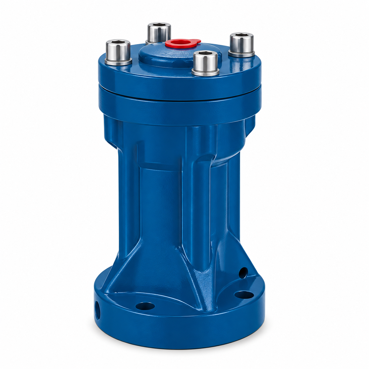
Model specifications
Series 01- Series
- SK Pneumatic Impact Hammer
Technical specifications
Operating data- Operating pressure: 3-7 kgf/cm²; see individual model limits
- Action: Intermittent impact
- Control valve: 3/2-way solenoid valve
- Impact timing: Adjustable with an external controller
- Models: SK-30 / SK-30LP / SK-40 / SK-40LP / SK-60 / SK-60LP / SK-80 / SK-80LP / SK-100 / SK-100LP
SK performance
| Model | operating pressure (kgf/cm²) | Air consumption per impact (L) | Impact impulse (kg·m/s) | Weight (kg) |
| SK-30 | 3-7 | 0.028 | ≈0.75 | 1.1 |
| SK-30LP | 3-7 | 0.028 | ≈1.1 | 1.2 |
| SK-40 | 3-7 | 0.082 | ≈2.2 | 2.2 |
| SK-40LP | 3-7 | 0.082 | ≈3.3 | 2.5 |
| SK-60 | 3-7 | 0.228 | ≈7.4 | 5.1 |
| SK-60LP | 3-7 | 0.228 | ≈11.1 | 5.7 |
| SK-80 | 4-5 | 0.455 | ≈16.4 | 11.1 |
| SK-80LP | 4-5 | 0.455 | ≈24.6 | 12.0 |
| SK-100 | 5-7 | 1.012 | ≈30.0 | 37.5 |
| SK-100LP | 5-7 | 1.012 | ≈45.0 | 36.4 |
Use a 3/2-way solenoid valve to admit and exhaust air. Set the impact interval and valve-on time with the controller.
Supply clean, dry, filtered air. Contamination accelerates seal and valve wear.
The illustrated control arrangement uses AC 220 V, 50 Hz and 8 mm or 10 mm tubing with a matching inlet connector.
The controller valve-on time is adjustable from 0.1 to 9.9 seconds. Set the interval to suit the material and installation.
Inspect the hammer and renew its grease after approximately two months of service.
R identifies the compressed-air inlet and G the exhaust port. All dimensions are in millimetres except the stated port threads.
SK 30-80 dimensions
| Model | A (mm) | B (mm) | C (mm) | D (mm) | E (mm) | G (in) | H (mm) | L (mm) | S (mm) | T (mm) | Y (mm) | R (in) |
| SK-30 | 75 | 10 | 82 | 13 | 9 | 1/8 | 132 | 68 | 6 | 50 | 27 | 1/4 |
| SK-40 | 90 | 12 | 97 | 18 | 11 | 1/4 | 162 | 78 | 10 | 60 | 34 | 1/4 |
| SK-60 | 121 | 13 | 143 | 19 | 15 | 1/4 | 215 | 110 | 10 | 60 | 48 | 1/4 |
| SK-80 | 160 | 17 | 170 | 20 | 17 | 3/8 | 260 | 140 | 14 | 90 | 70 | 3/8 |
Weld the mounting base securely to the vessel and tighten the hammer to the base with bolts and nuts. Check the mounting regularly.
Add a reinforcing plate between the mounting base and a thin vessel wall.
SK 100 dimensions
| Model | A (mm) | B (mm) | C (mm) | D (mm) | E (mm) | G (in) | H (mm) | L (mm) | S (mm) | T (mm) | Y (mm) | R (in) |
| SK-100 | 200 | 18 | 200 | 23 | 17 | 3/8 | 318 | 160 | 18 | 90 | 70 | 3/8 |
Weld the mounting base securely to the vessel and tighten the hammer to the base with bolts and nuts. Check the mounting regularly.
Add a reinforcing plate between the mounting base and a thin vessel wall.
SK LP 30-80 dimensions
| Model | A (mm) | B (mm) | C (mm) | D (mm) | E (mm) | G (in) | H (mm) | L (mm) | S (mm) | T (mm) | R (in) | Z (mm) | M (mm) | P (mm) |
| SK-30LP | 75 | 10 | 82 | 13 | 9 | 1/8 | 132 | 68 | 100 | 50 | 1/4 | 20 | 25 | 25 |
| SK-40LP | 90 | 22 | 97 | 18 | 11 | 1/4 | 162 | 78 | 150 | 60 | 1/4 | 25 | 25 | 35 |
| SK-60LP | 121 | 13 | 143 | 19 | 15 | 1/4 | 215 | 110 | 200 | 60 | 1/4 | 40 | 25 | 35 |
| SK-80LP | 160 | 17 | 170 | 20 | 17 | 3/8 | 260 | 140 | 200 | 60 | 3/8 | 50 | 25 | 35 |
Secure the bracket to a fixed support as shown in the installation drawing. Confirm the striking direction and contact position before operation.
SK LP 100 dimensions
| Model | A (mm) | B (mm) | C (mm) | D (mm) | E (mm) | G (in) | H (mm) | L (mm) | S (mm) | T (mm) | R (in) | Z (mm) | M (mm) | P (mm) |
| SK-100LP | 200 | 18 | 200 | 3 | 17 | 3/8 | 318 | 160 | 200 | 60 | 3/8 | 50 | 15 | 45 |
Secure the bracket to a fixed support as shown in the installation drawing. Confirm the striking direction and contact position before operation.
SK selection guide
| Parameter | Selection guidance |
| Hopper geometry | The selection chart is based on a conical hopper with an approximately 60° wall angle. |
| D | Hopper diameter in millimetres. |
| t | Thickness of the conical hopper wall in millimetres. |
| Model | The vertical regions identify hammer sizes 30, 40, 60, 80 and 100. |
| Quantity | The horizontal regions indicate 1, 2, 3 or 4 hammers. |
| Selection example | For a 1500 mm diameter hopper with a 3 mm wall, the SK chart indicates two SK-60 hammers. |
| Material properties | Hopper shape, bulk-material properties and material condition can change the required model and quantity. |
SK LP selection guide
| Parameter | Selection guidance |
| Hopper geometry | The selection chart is based on a conical hopper with an approximately 60° wall angle. |
| D | Hopper diameter in millimetres. |
| t | Thickness of the conical hopper wall in millimetres. |
| Model | The vertical regions identify hammer sizes 30, 40, 60, 80 and 100. |
| Quantity | The horizontal regions indicate 1, 2, 3 or 4 hammers. |
| Selection example | For a 1500 mm diameter hopper with a 3 mm wall, the SK LP chart indicates two SK-40LP hammers. |
| Material properties | Hopper shape, bulk-material properties and material condition can change the required model and quantity. |
Hammer operating cycle
| Stage | Operation |
| YL1 | With the air supply off, magnetic attraction holds the piston in its starting position. |
| YL2 | The 3/2-way solenoid valve admits compressed air and pressure builds above the piston. |
| YL3 | Air pressure overcomes the magnetic holding force. The piston accelerates and delivers an impact to the mounting base. |
| YL4 | The valve exhausts the chamber. The return spring raises the piston until magnetic attraction holds it again. |
Diagram key: 1 = piston; 2 = magnetic retaining plate; 3 = impact base; 4 = return spring. The other callouts identify the 3-way valve, piston ring, O-ring and magnet.
Hammer installation: hopper
| application | Mounting guidance |
| Hopper | Position the hammer approximately one-quarter to one-third of the sloping wall length above the outlet. |
Hammer installation: blocked pipe
| application | Mounting guidance |
| Blocked pipe | Position the hammer near the midpoint of the affected pipe section. |
Hammer installation: poorly flowing material
| application | Mounting guidance |
| Poorly flowing material | Use staggered hammers around the hopper; the illustrated positions are one-quarter and one-third of the sloping wall length above the outlet. |
Hammer installation: rotating container
| application | Mounting guidance |
| Rotating container | Use an external mounting arrangement that transfers impact to the rotating container. |