

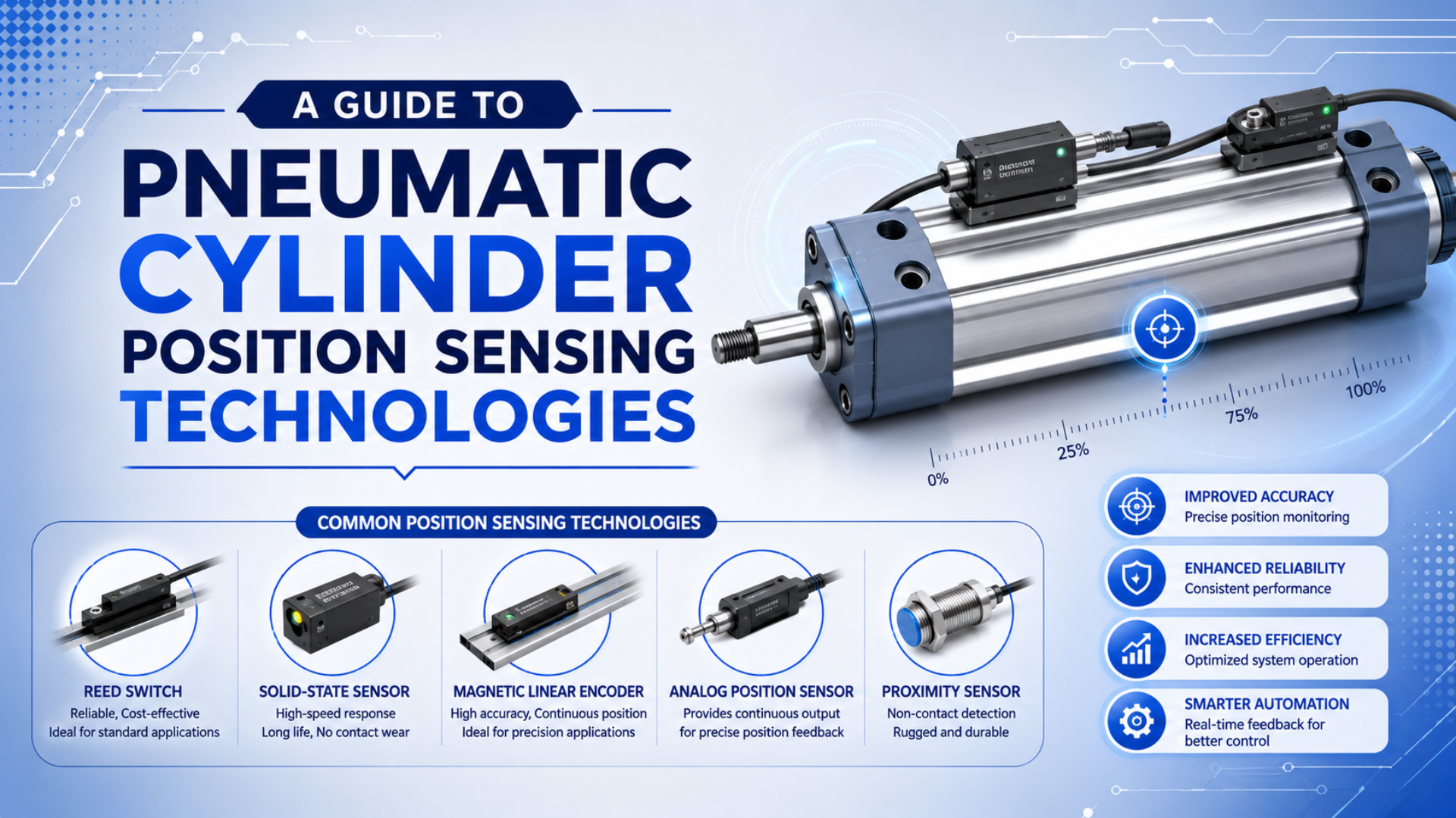
Pneumatic cylinder position sensing is the use of switches, proximity sensors, transducers, or encoders to tell a controller where a pneumatic actuator is during its stroke. The sensor may only prove “extended” or “retracted.” It may also report a zone, a measured analog position, or a digital position value for closed-loop control.
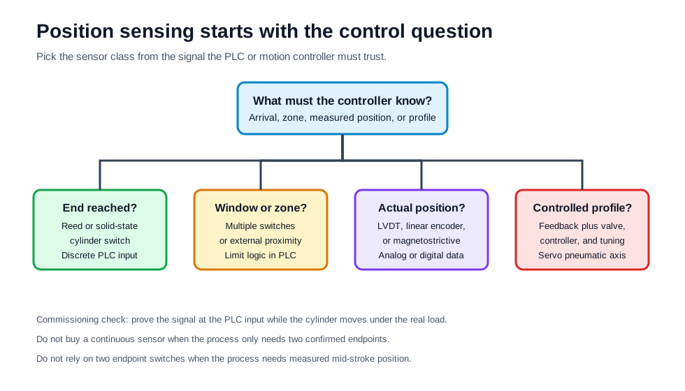
The practical choice starts with the control question. Do you need a safe endpoint confirmation, a mid-stroke window, actual continuous position, or a feedback signal for a servo pneumatic axis? Those four jobs use different sensors, different PLC inputs, and different commissioning tests. A low-cost reed switch can be perfect for a clamp. It is the wrong answer for a cutting head that must stop at several recipe positions.
Key Takeaways
- Use reed or solid-state cylinder switches when the PLC only needs endpoint or simple zone confirmation.
- Use LVDTs, magnetostrictive sensors, potentiometers, or linear encoders when the controller needs measured position across the stroke.
- TE Connectivity describes LVDTs that can measure very small movement and positions up to +/-30 inches, but machine accuracy still depends on mounting, load, air behavior, and test method.
- Treat position feedback as part of a system: actuator, guide, valve, sensor, cable, PLC input, and acceptance test.
What Does Pneumatic Cylinder Position Sensing Need to Prove?
Pneumatic cylinder position sensing needs to prove one of four things: the actuator reached an endpoint, the actuator entered a defined zone, the moving member sits at a measured position, or the axis followed a controlled motion profile. The first two are discrete sensing jobs. The last two need continuous feedback or a higher-resolution position device. That distinction prevents most bad sensor purchases because a switch cannot become an encoder after the machine is built.
If the cylinder only moves between two mechanical stops, a pair of cylinder switches is often enough. The PLC asks, “Did the cylinder reach the extend switch before the timeout?” If the process needs a selected stop point, the question changes. Now the controller asks, “Where is the carriage right now?” For a review of the basic cylinder cycle, see the guide on how a pneumatic cylinder works in automation.
Endpoint sensing means a discrete signal that confirms a final or near-final position. It normally feeds a standard PLC digital input.
Continuous position feedback is a measured signal across a stroke. It can be analog, incremental, absolute, or networked, depending on the device and controller.
In our experience, the expensive mistake is buying “a more accurate sensor” before defining what accuracy means. A sensor may resolve a small movement, but the machine may still miss the workpiece because the guide flexes, the cylinder seals stick, or the load shifts. Define the process result first. Then choose the sensor.
At a Glance: Sensor Choices
The table below is a starting point, not a catalog substitute. It separates the sensor job from the output signal. Use it before asking for part numbers.
| Control need | Typical sensor choice | PLC or controller input | Best fit | Watch point |
|---|---|---|---|---|
| Extend/retract proof | Reed switch or solid-state cylinder switch | Discrete PNP/NPN | Two-position cylinders and clamps | Magnet strength, slot fit, cable routing |
| Zone detection | Multiple cylinder switches or external proximity sensors | Several discrete inputs | Pick windows, transfer confirmation, indexing | Switch spacing and PLC logic |
| Short-stroke measured position | LVDT or potentiometer | Analog voltage/current | Press, clamp, gauge, or test fixture feedback | Mechanical linkage and signal conditioning |
| Long-stroke measured position | Magnetostrictive sensor or linear encoder | Analog, SSI, IO, or encoder input | Guided slides, rodless axes, adjustable stops | Mounting straightness and environmental protection |
| Motion profile control | Feedback sensor plus proportional valve and controller | Motion, analog, or high-speed interface | Servo pneumatic positioning | Tuning, air supply, load, and acceptance test |
Which Sensor Types Fit End-Position and Zone Detection?
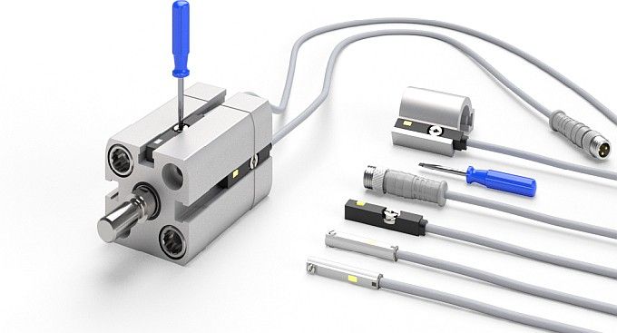
Magnetic cylinder switches fit many endpoint and zone detection tasks because the piston magnet moves with the cylinder and triggers a sensor mounted in the body slot or along the barrel. SICK groups magnetic cylinder sensors under position sensors for pneumatic cylinder detection (SICK Magnetic Cylinder Sensors, 2026). That category covers the common automation need: a compact sensor that tells the PLC the piston passed a known location.
Reed Switches
Reed switches are simple magnetic switches. A piston magnet closes the reed contact when it comes into range. They are low-cost, easy to understand, and useful for basic extend/retract feedback. They also have limits. Contacts can bounce. Response can vary with magnet strength and mounting position. They are not a good way to measure continuous motion.
Use reed switches when the machine has two stable end positions, modest cycle speed, and standard PLC digital inputs. For example, a packaging stop gate may only need “gate up” and “gate down” confirmation before the conveyor restarts.
Solid-State Cylinder Switches
Solid-state switches use electronic sensing rather than a mechanical reed contact. They often fit higher cycle counts, cleaner switching, and compact sensor slots. Some models include LED indication or short-circuit protection. However, the output type must match the PLC input. A PNP sensor wired to an NPN input will not become reliable because the mechanical mount is correct.
In our experience, many “bad sensor” calls are wiring calls. Confirm voltage, PNP or NPN, normally open or normally closed, connector pinout, and input common before moving the switch.
External Proximity Sensors
External proximity sensors sense a flag, bracket, carriage, or target instead of the piston magnet. They are useful when the cylinder body has no sensor slot, the piston magnet is weak, or the real process datum is not the piston. That last point matters. Sometimes the PLC should confirm the guided slide or gripper jaw, not the internal piston.
External sensors add brackets and alignment work. The benefit is control over the target. If the fixture position matters more than piston position, sense the fixture.
When Do You Need Continuous Position Feedback?
You need continuous position feedback when endpoint switches cannot answer the process question. If the cylinder must stop at recipe positions, record a measured displacement, follow a speed profile, or prove a final position that is not a hard stop, use a position transducer or encoder. TE Connectivity explains that an LVDT converts rectilinear motion into an electrical signal and can support very small displacement measurement as well as positions up to +/-30 inches in some configurations (TE Connectivity LVDT Tutorial, 2026).
The key is to separate sensor capability from machine result. A high-resolution sensor can report motion that the pneumatic system cannot repeat under load. Air compresses, seals create friction, and the carriage can deflect. Therefore, the RFQ should state both the sensor signal and the acceptance test. “Analog position over 500 mm stroke” is incomplete. “Hold the loaded carriage within +/-0.5 mm for 2 seconds at 6 bar supply” is testable.
Potentiometers
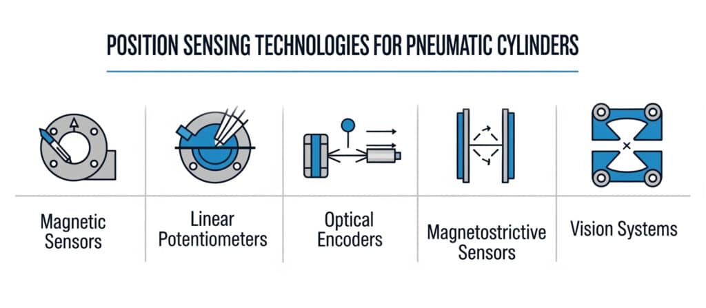
Linear potentiometers produce a voltage related to position. They are easy to interface with many analog inputs and can be cost-effective for short to moderate strokes. The tradeoff is mechanical wear and linkage quality. If vibration, dust, washdown, or long life is the priority, check the mechanical construction carefully.
LVDTs
LVDTs are non-contact inductive displacement sensors with a movable core. They are common in measurement, test, press, clamp, and short-stroke feedback tasks. TE notes that AC LVDTs need external signal conditioning while DC LVDTs include electronics. That choice affects panel wiring, noise behavior, and spare-parts planning.
Magnetostrictive Sensors
Magnetostrictive sensors can provide absolute position without a sliding electrical contact. They are often considered when the stroke is longer, the environment is industrial, and the controller needs a repeatable position value after power-up. Match the active stroke, mounting method, output type, and update behavior before quoting.
Linear Encoders
Linear encoders fit guided axes that need measured carriage position rather than only piston position. HEIDENHAIN separates linear encoders into sealed and exposed types, which is a useful design distinction because contamination, coolant, dust, and alignment tolerance affect the choice (HEIDENHAIN Linear Encoders, 2026). A clean lab axis and a sawdust transfer line should not use the same feedback plan.
How Should the PLC Interface Shape the Sensor Choice?
The PLC interface should shape the sensor choice before the purchase order. A sensor that fits the cylinder but not the controller creates field rewiring, converter boxes, or hidden timing faults. Check voltage, output type, input card, scan time, analog resolution, shielding, cable length, and diagnostic needs. For a basic two-position cylinder, a digital input is enough. For measured position, the controller needs analog, encoder, serial, or networked data that the program can scale and validate.
Discrete sensors usually raise four questions. Is the output PNP or NPN? Is it normally open or normally closed? Does it run on the available 24 VDC supply? Does the input card share the same common? Those details sound small until a machine ships to a plant that uses the opposite input convention.
Analog feedback raises different questions. Is the signal 0-10 V, 4-20 mA, or another range? What happens at wire break? Does the input have enough resolution for the tolerance target? Is the cable shield grounded correctly? A noisy analog signal can look like cylinder drift when the real fault is electrical noise.
Encoder-style feedback adds timing questions. Does the controller accept incremental pulses, absolute data, or a fieldbus object? Does the scan or motion task read the position fast enough? Does the machine need position after power-up without homing? These questions belong in the controls review, not at the end of commissioning.
For proportional or servo pneumatic positioning, read this guide together with the article on servo control pneumatic systems and positioning accuracy. A sensor alone does not close the loop. The valve, controller, tuning, air supply, and mechanics decide whether feedback becomes usable motion.
Which Position Sensors Work Best with Rodless Cylinders?
Rodless cylinders need the same sensing decision, but the moving member is usually a carriage rather than a rod end. For simple end confirmation, magnetic switches mounted along the cylinder body may be enough if the cylinder design supports them. For long-stroke positioning, the more useful feedback point is often the carriage, guide, or tooling plate. That is why rodless axes often use external linear encoders, magnetostrictive sensors, or multiple zone sensors on the machine frame.
A rodless cylinder also makes sensor mounting more visible. Long strokes magnify cable management problems. Carriage motion can cross washdown spray, dust, guarding, or operator access areas. If the sensor cable flexes every cycle, plan the carrier, connector, and strain relief at the same time as the cylinder.
In our experience, the best rodless-cylinder sensing plan starts from the payload. If the process datum is the tooling plate, sense the tooling plate or the guided carriage. If the process only needs end-of-stroke confirmation, do not add a linear encoder to make the design look more technical. The right sensor is the lowest-complexity device that proves the required state under load.
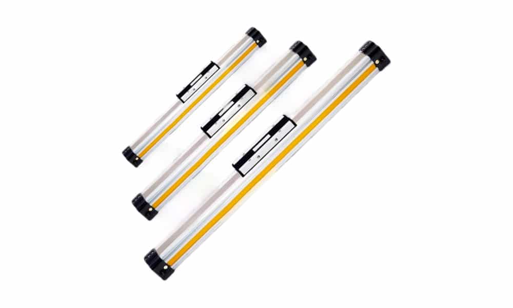
For broader mechanical tradeoffs, the rodless cylinder advantages guide explains why long stroke length, compact footprint, and carriage loading change the sensor plan.
How Do Environment, EMI, and Mounting Change the Answer?
Environment changes the answer because sensors fail in different ways. Magnetic switches can suffer from weak actuation or stray magnetic influence. Analog feedback can pick up electrical noise. Optical or exposed encoder systems can struggle with dirt, oil mist, coolant, or chips. Potentiometers can wear. Cable jackets can crack under washdown chemicals or repeated flexing. The sensor data sheet matters, but the installation around the sensor matters just as much.
Use the environment list below during design review:
- Temperature: Check sensor rating, cable jacket, connector, and any amplifier electronics.
- Moisture and washdown: Check IP rating, connector sealing, cable entry direction, and water traps.
- Dust and chips: Avoid exposed optical paths unless guarding and cleaning are planned.
- Magnetic fields: Keep magnetic cylinder switches away from strong external fields where possible.
- Vibration: Lock sensor brackets and protect connectors from cyclic movement.
- EMI: Separate analog and encoder cables from solenoid coils, drives, welders, and power wiring.
- Mechanical datum: Sense the part of the machine that actually defines process position.
That last item is often missed. Piston position is not always tooling position. A loose coupling, worn guide, flexible bracket, or long overhung load can make the piston signal look perfect while the workpiece is wrong.
Pressure and flow behavior also affect what the sensor appears to report. If the cylinder slows or rebounds, the sensor may be blamed when the real fault is pressure drop, exhaust restriction, or cushion setting. Start with the troubleshooting guide on pressure drop in pneumatic systems when timing changes across the shift.
What Should Engineers Test During Commissioning?
Commissioning should prove the sensor signal at the controller under real motion, not only on a bench. Watch the input status, analog value, or encoder count while the cylinder moves at production speed and load. Then compare the controller value with the mechanical result. NIST’s work on single-axis positioning system evaluation is a useful reminder that position claims need a measurement method, not only a target number (NIST Single-Axis Positioning Systems, 2020).
Use this commissioning checklist:
- Confirm sensor part number, output type, cable pinout, and supply voltage.
- Move the sensor slowly through its switching or measuring range.
- Verify the signal at the PLC input, not only at the sensor LED.
- Run the cylinder at production speed and load.
- Record extend time, retract time, in-position delay, and missed-signal faults.
- Check that analog or encoder values scale correctly at both ends of stroke.
- Test the machine after power cycling, air dump, E-stop, and recovery.
- Pull gently on the cable and connector while watching for signal dropout.
- Confirm fault logic for impossible states, such as both end sensors active.
- Document final sensor location before the machine leaves the shop.
If timing matters, use the response-time article on measuring pneumatic solenoid valve response beside the sensor test. A slow valve, undersized exhaust, or sticky seal can create a late signal even when the sensor is healthy.
Pneumatic Cylinder Position Sensor RFQ Checklist
Send the data below before asking for a sensor quote. It will save a round of emails and reduce the chance that the part fits the cylinder but not the machine.
| RFQ item | What to send | Why it matters |
|---|---|---|
| Cylinder type | Tie-rod, round body, compact, guided, or rodless | Defines sensor mounting options |
| Bore and stroke | Example: 50 mm bore, 600 mm stroke | Sets magnet distance and feedback range |
| Required signal | End, zone, analog position, encoder, or servo feedback | Chooses the sensor class |
| Controller input | PNP, NPN, 0-10 V, 4-20 mA, encoder, or network | Avoids interface mismatch |
| Process tolerance | Example: confirm zone within 5 mm, or hold position within 0.5 mm | Defines acceptance, not just resolution |
| Speed and cycle rate | Stroke time and cycles per minute | Affects response and cable duty |
| Load and guide | Moving mass, side load, orientation, external guide | Separates piston position from tooling position |
| Environment | Temperature, washdown, dust, oil, weld area, cleanroom | Defines housing, cable, and protection needs |
| Cable route | Fixed, flexing, drag chain, connector type | Prevents intermittent faults |
| Failure behavior | Safe state on wire break or missed signal | Shapes normally open/closed and diagnostics |
For project review, send these details with photos or drawings through contact. The engineering context on about us explains how Bepto reviews actuator, valve, sensor, and air-system fit as one package.
Common Selection Mistakes
The first mistake is overbuying continuous feedback for a two-position job. If a hard stop defines the process and the PLC only needs arrival proof, a pair of well-mounted switches may be more reliable than an analog sensor that nobody scales or monitors correctly.
The second mistake is underbuying for mid-stroke control. Two end switches cannot verify a recipe stop in the middle of the stroke. Multiple zone switches can confirm windows, but they still do not provide a continuous position value.
The third mistake is treating sensor resolution as machine accuracy. A sensor may report small movement while the cylinder, guide, load, valve, and air supply create a larger process error. Therefore, specify the loaded acceptance test before selecting feedback.
The fourth mistake is sensing the wrong part. If the tooling plate defines the process, sensing the piston magnet may only confirm that the piston moved. It may not confirm that the tooling reached the datum.
The fifth mistake is ignoring wiring until startup. Sensor output type, shield grounding, connector pinout, input common, and cable flex rating should be reviewed with the mechanical design. Otherwise, commissioning becomes a wiring investigation.
Conclusion
Pneumatic cylinder position sensing is not one technology. It is a decision about what the controller needs to know and how much evidence the process requires. Use magnetic or solid-state switches for endpoint and zone confirmation. Use LVDTs, magnetostrictive sensors, potentiometers, or linear encoders when the controller needs measured position. Use feedback plus a valve and controller when the axis must follow a motion profile.
The best sensor is the one that proves the required machine state under real load. Define the signal, datum, interface, environment, and test method first. Then choose the sensor.
FAQs About Pneumatic Cylinder Position Sensing Technologies
These answers keep the selection boundary clear: a switch confirms state, a transducer measures position, and a servo pneumatic system uses feedback for control.
What is the best position sensor for a pneumatic cylinder?
The best position sensor depends on the control job. Use reed or solid-state switches for simple extend and retract confirmation. Use an LVDT, magnetostrictive sensor, potentiometer, or linear encoder when the controller needs measured position across the stroke. For servo pneumatic positioning, the sensor must be paired with a suitable valve, controller, tuning method, and acceptance test.
Are reed switches enough for mid-stroke positioning?
Reed switches can confirm a fixed mid-stroke zone if the tolerance is loose and the switch can be mounted at that location. They are not enough for continuous mid-stroke positioning or recipe-based stopping. If the cylinder must stop at many positions, use continuous feedback and a control strategy designed for positioning.
What is the difference between a cylinder switch and a linear encoder?
A cylinder switch gives a discrete on/off signal when the piston magnet or target reaches the sensing zone. A linear encoder reports measured position along an axis. The switch answers “has it arrived?” The encoder answers “where is it now?”
Can position sensors be retrofitted to existing pneumatic cylinders?
Yes, many can be retrofitted, but the method depends on the cylinder body, piston magnet, stroke, mounting space, and controller input. Slotted cylinders may accept magnetic switches. Older cylinders may need external proximity sensors or a feedback device mounted to the guided mechanism.
How do I avoid false cylinder sensor signals?
Avoid false signals by matching the output type to the PLC input, securing the bracket, protecting the cable, separating sensor wiring from noisy power wiring, and testing the signal during real motion. Also check the mechanical datum. A perfect piston signal can still be wrong if the tooling is loose.
What should I send for a pneumatic cylinder sensor RFQ?
Send cylinder type, bore, stroke, required signal, controller input, tolerance, speed, load, environment, cable route, and failure-state requirements. Photos or drawings help. The supplier needs to know whether you need endpoint proof, zone confirmation, measured position, or closed-loop feedback.
External Technical References
- TE Connectivity: Understanding LVDTs, LVDT operating concept, measurement range, and signal-conditioning notes. Retrieved 2026-07-08.
- HEIDENHAIN Linear Encoders, sealed and exposed linear encoder product categories. Retrieved 2026-07-08.
- SICK Magnetic Cylinder Sensors, magnetic cylinder sensor category for pneumatic position detection. Retrieved 2026-07-08.
- NIST: Development of a New Standard for the Performance Evaluation of Single Axis Linear Positioning Systems, context for position accuracy and evaluation method. Retrieved 2026-07-08.