

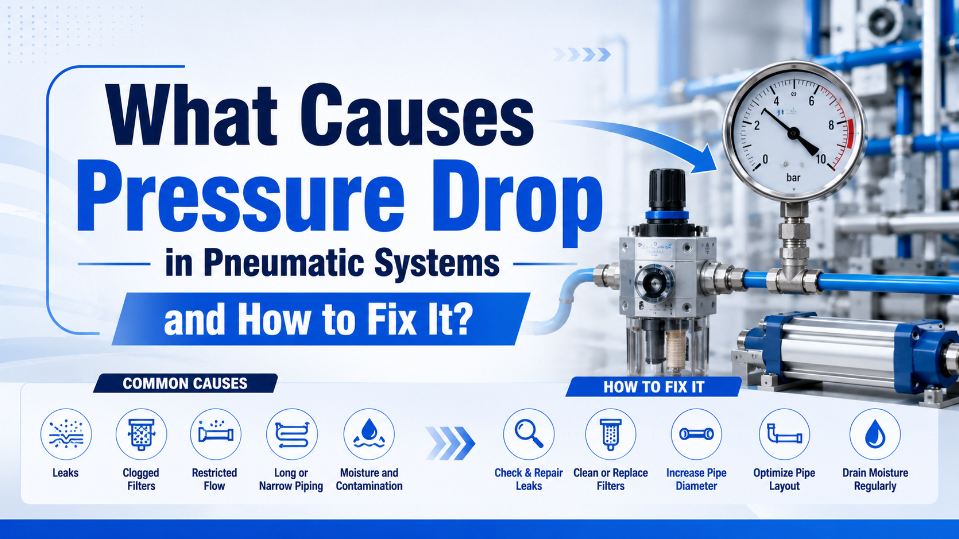
Pressure drop in pneumatic systems is the loss of air pressure between the compressor discharge and the point where work happens. It occurs when compressed air flows through pipe, tubing, filters, regulators, valves, fittings, mufflers, leaks, and actuator ports that resist flow.
The fix is not to raise compressor pressure first. Measure pressure while the machine is moving, locate the largest loss, clean or resize the restriction, repair leaks, and then lower system pressure back to the minimum value that keeps the actuator reliable.
Key Takeaways
- CAGI says a well-designed compressed air system should stay within 10% pressure drop from compressor discharge to point of use.
- DOE reports leaks can waste 20-30% of compressor output in poorly maintained compressed air systems.
- Static gauge readings are not enough. Measure dynamic pressure before and after filters, regulators, valves, tubing, and actuators during the fault cycle.
The useful troubleshooting question is not “What is my compressor pressure?” It is “What pressure reaches the actuator during the fastest or heaviest part of the cycle?” Those are often different numbers.
What Causes Pressure Drop in Pneumatic Systems?
Pressure drop is the pressure lost between two points while compressed air flows through resistance. CAGI’s pressure-drop brief says losses occur through piping, fittings, filters, dryers, and components, and that well-designed systems should have no more than 10% drop between compressor discharge and point of use (CAGI Pressure Drop Technical Brief, 2026).
The common causes are simple, but they hide in different places:
| Cause | What happens under flow | Field symptom |
|---|---|---|
| Undersized tube or pipe | Velocity rises and friction loss increases | Cylinder slows during fast cycles |
| Too many fittings or sharp bends | Equivalent length increases | Good static pressure, weak dynamic pressure |
| Dirty filter element | Differential pressure rises across the filter | Pressure recovers after filter change |
| Undersized regulator or FRL | Set pressure holds at rest but sags under demand | Gauge droops when the valve opens |
| Low-Cv valve or small manifold | Valve cannot pass peak flow without loss | Slow extension or weak clamp force |
| Restrictive exhaust muffler | Return air cannot leave fast enough | Retraction is slow or jerky |
| Leaks | Compressor flow is consumed before useful work | Header pressure falls during production |
| Water, oil, corrosion, or debris | Effective passage size shrinks | Symptoms get worse over time |
The mistake is treating every pressure drop as a compressor problem. For example, a compressor can supply 7 bar while a cylinder receives 5.5 bar during motion because a filter, quick disconnect, hose, or valve between them is doing the damage.
For related flow theory, keep this article separate from the air flow to pressure guide. That guide explains why flow cannot be converted directly into pressure. This one is about finding and fixing the loss path.
In our experience, the biggest field wins usually come from boring measurements: compare pressure upstream and downstream of each suspected part while the actuator moves. Static readings miss the problem.
Where Should You Measure Pressure Drop First?
Dynamic pressure is the pressure recorded while the actuator, valve, or tool is actually consuming air. Measure pressure drop at the compressor outlet, after the dryer, after the main filter, at the header, before and after the local FRL, at the valve inlet, at the valve outlet, and at the actuator port. DOE says excessive pressure drop causes poor performance and extra energy use, so local measurement matters (DOE Sourcebook, 2022).
Start at the machine, not in the compressor room. If the fault is a weak clamp or a slow rodless cylinder, the actuator port is the truth point. The header gauge only tells you the system average.
Use two gauges or pressure sensors when possible:
- Put one sensor upstream of the suspected restriction.
- Put the second sensor downstream, as close to the actuator or valve as practical.
- Cycle the machine at the speed and load that creates the fault.
- Record the minimum pressure during motion, not only the resting value.
- Move the sensors one component at a time until the largest drop appears.
| Measurement pair | What it reveals | First action if drop is high |
|---|---|---|
| Dryer inlet vs outlet | Dryer or separator restriction | Service dryer, drains, separator |
| Filter inlet vs outlet | Loaded filter element | Replace filter element |
| Regulator inlet vs outlet | Regulator flow capacity | Resize regulator or reduce branch demand |
| Valve inlet vs outlet | Valve Cv or manifold restriction | Select higher-Cv valve or manifold |
| Tube start vs actuator port | Tubing, fittings, quick disconnects | Increase tube ID or remove restrictions |
| Cylinder inlet vs exhaust | Supply or exhaust choking | Check speed controls and mufflers |
This sequence also separates pressure drop from pressure fluctuation. Drop is a loss between two points. Fluctuation is a time-varying sag or pulse at one point.
The Highest-Risk Restriction Points
Equivalent length is the straight-pipe length added to represent elbows, tees, quick disconnects, reducers, and other local restrictions. The highest-risk restriction points are dirty filters, undersized hoses, small quick disconnects, low-Cv valves, restrictive manifolds, and long point-of-use tubing. CAGI recommends air velocity through piping at 20 ft/s or lower and replacing filters when differential pressure exceeds 5-7 psig (CAGI Pressure Drop Technical Brief, 2026).
Look for these parts first when a machine is slow only under load:
- Filters and coalescing elements: A loaded element can look clean from the outside. Use differential pressure, not calendar time alone.
- Regulators and FRL units: A pressure regulator may hold a setpoint at rest but sag when a valve bank opens.
- Quick disconnects: Small couplers are convenient but can become the narrowest passage in a high-flow branch.
- Long polyurethane tubing: Tube ID matters more than the outside size printed on the tube.
- Valve islands and manifolds: Common passages can starve simultaneous valves even when each valve looks correctly sized.
- Mufflers and meter-out controls: Exhaust restrictions slow return strokes and can be mistaken for supply pressure loss.
- Water and oil contamination: Condensate, rust, and oil film reduce effective area and add unpredictable losses.
When reviewing pneumatic fittings, do not count pieces only. Count effective restrictions. A straight large-bore fitting may be harmless in one branch, while a small quick-connect pair can dominate the pressure loss at a fast actuator.
The most suspicious component is the one that sees peak flow, not the one with the biggest thread size. Port size, tube ID, internal passage, and Cv can all disagree.
How Does Pressure Drop Affect Pneumatic Cylinders and Rodless Cylinders?
Pressure drop reduces cylinder force because pneumatic force is pressure times effective piston area. If point-of-use pressure falls 10%, available theoretical force falls about 10% before friction, load angle, seal drag, and guide load are considered. That is why CAGI’s 10% system-drop target is a useful limit (CAGI Pressure Drop Technical Brief, 2026).
A cylinder can fail in three different ways when pressure falls:
| Symptom | Likely mechanism | What to check |
|---|---|---|
| Slow extension | Supply path cannot feed chamber fast enough | Valve Cv, tube ID, fittings, regulator |
| Weak clamp force | Actuator pressure is below design pressure | Port pressure during clamp, bore sizing |
| Jerky motion | Pressure sag changes through the stroke | Flow controls, load, seals, pressure log |
| Slow retraction | Exhaust path is restricted | Muffler, meter-out control, valve exhaust |
| Incomplete stroke | Force margin is gone at the load peak | Load, friction, guide binding, pressure drop |
Rodless cylinders are especially sensitive because long strokes, guide loads, and moving carriage friction can expose marginal pressure. For instance, a long transfer axis may look acceptable during manual jogging but lose timing when the full automatic sequence opens several valves together.
Use the working pressure guide for force margin and pressure setpoint decisions. Use this guide when the setpoint is correct but pressure fails to reach the actuator under flow.
If the issue appears only at higher speed, compare supply pressure with speed demand. A fast stroke requires more flow. More flow through the same restriction produces more pressure drop.
How Do You Calculate Pressure Drop Without Guessing?
Calculate pressure drop by combining measured flow demand, line length, inside diameter, equivalent fitting length, working pressure, and component flow data. ISO 6358 defines steady-state flow-rate characteristics for pneumatic components, while practical field work often starts with manufacturer Cv curves and measured pressure differences (ISO 6358-1, 2013).
For tubing and pipe, use the variables that actually control loss:
Pressure drop inputs:
flow demand
pipe or tube inside diameter
straight length
equivalent fitting length
working pressure
air temperature
roughness and contamination
The strong relationship is diameter. A small increase in inside diameter can reduce line loss sharply because friction formulas penalize small passages. That is why replacing a long small tube can beat raising compressor pressure.
For valves, fittings, and manifolds, use Cv or the manufacturer’s pressure-flow chart. A simplified Cv relationship is:
Q = Cv x sqrt(DeltaP x SG)

Q      = flow rate
Cv     = flow coefficient
DeltaP = pressure drop across the component
SG = specific gravity referenceKeep this calculation boundary clear: formulas estimate clean, steady conditions. Real machines pulse. Measure after calculating, especially on high-speed pneumatic cylinders and valve banks.
Fix Pressure Drop in the Right Order
Fix leaks, filters, tubing, fittings, valves, and local storage before increasing compressor pressure. DOE’s compressed-air guidance reports that leaks can account for 20-30% of compressor output in poorly maintained systems, and CAGI warns that raising pressure or adding compressors should not be the first response (DOE Sourcebook, 2022; CAGI Pressure Drop Technical Brief, 2026).
Use this order:
- Document the fault cycle: Record machine state, actuator stroke, load, speed setting, and simultaneous air users.
- Measure dynamic pressure: Log upstream and downstream pressure while the fault occurs.
- Replace loaded filters: Follow differential-pressure limits and replace suspect elements.
- Repair audible and ultrasonic leaks: Leaks reduce available flow and lower system pressure.
- Remove needless restrictions: Reduce quick disconnects, sharp bends, reducers, and undersized fittings.
- Increase tube or hose ID where needed: Confirm with velocity and pressure-drop checks.
- Resize low-Cv valves and manifolds: Match peak flow, not only port thread.
- Add local receiver storage for intermittent demand: Place storage near the high-flow event.
- Retune regulators and speed controls: Set pressure and flow after restrictions are fixed.
- Only then review compressor pressure or capacity: Do not buy supply capacity to hide a local bottleneck.
This order saves energy. If you raise header pressure first, every leak and unregulated branch consumes more air. If you fix the bottleneck first, the weak station often recovers without making the whole plant more expensive.
For energy-specific work, use the broader pneumatic energy efficiency guide. For this article, the narrower goal is pressure-drop correction.
RFQ and Maintenance Checklist
For a maintenance or replacement request, include the measured pressure drop, flow demand, tube ID, length, fitting count, valve Cv, filter size, regulator model, actuator bore, stroke, load, and cycle rate. CAGI recommends adding taps for pressure monitoring, and that one small design detail makes future diagnosis faster (CAGI Pressure Drop Technical Brief, 2026).
Send this information when asking for a component review or technical support:
| Data point | Why it matters |
|---|---|
| Compressor discharge pressure | Establishes upstream supply |
| Header pressure during fault | Shows whether the issue is plant-wide |
| FRL inlet and outlet pressure | Identifies filter or regulator drop |
| Valve inlet and outlet pressure | Tests valve Cv and manifold limits |
| Actuator port pressure during motion | Shows the useful pressure at work |
| Flow demand or cycle rate | Connects pressure drop to peak air use |
| Tube ID and total length | Drives friction and response time |
| Fittings and quick disconnect count | Adds equivalent length and local loss |
| Actuator bore, stroke, and load | Confirms force margin |
| Temperature, water, and oil observations | Flags contamination and freeze risk |
When we review a slow actuator case, photos help less than numbers. A gauge video during the fault cycle, a tube ID measurement, and the valve model usually shorten the diagnosis more than a long description.
FAQs About Pressure Drop in Pneumatic Systems
FAQ diagnosis should start with measured point-of-use pressure under flow. CAGI’s 10% pressure-drop target and DOE’s 20-30% leak-waste range give practical thresholds, but the machine-specific answer comes from upstream and downstream pressure readings during the fault cycle (CAGI, 2026; DOE Sourcebook, 2022).
What is acceptable pressure drop in a pneumatic system?
CAGI says well-designed compressed air systems should have no more than 10% pressure drop between compressor discharge and any point of use. Critical actuators may need a tighter local limit if force margin is small, cycle time is short, or several valves open at once.
Can pressure drop make a pneumatic cylinder slower?
Yes. A cylinder needs pressure for force and flow for speed. When pressure drops during motion, the cylinder may lose force margin and fill more slowly. Check valve Cv, tube ID, fitting restrictions, regulator flow capacity, and exhaust mufflers before replacing the actuator.
Why does pressure look normal until the machine runs?
At rest, little air flows, so restrictions create little loss. When the valve opens, flow demand rises and the same restriction creates pressure drop. That is why static gauges can look normal while dynamic point-of-use pressure falls during the production cycle.
Should I raise compressor pressure to fix pressure drop?
Not first. Raising compressor pressure can hide a restriction and increase air waste through leaks or unregulated demand. Measure pressure drop across filters, regulators, valves, tubing, fittings, and exhaust parts first. Fix the largest local loss, then reset system pressure.
Which component should I check first?
Start with the component that sees the highest flow during the fault: local filter, regulator, valve, manifold, tube, quick disconnect, or muffler. If the whole header sags, check leaks, storage, compressor controls, and simultaneous demand. Use two gauges to avoid guessing.
How often should pressure drop be checked?
Check critical machines during planned maintenance and anytime cycle time, clamp force, or actuator motion changes. Filters should be checked by differential pressure, and CAGI identifies 5-7 psig differential pressure as a replacement trigger for filter elements in compressed-air systems.
Is pressure drop the same as a leak?
No. A leak wastes compressed air and can cause system pressure to fall, but pressure drop is the loss between two points while air flows through resistance. A system can have high pressure drop with no major leak if tubing, filters, valves, or fittings are undersized.
Sources
- CAGI: Pressure Drop Technical Brief, pressure-drop causes, 10% target, 20 ft/s velocity guidance, and 5-7 psig filter guidance. Retrieved 2026-07-08.
- DOE: Improving Compressed Air System Performance, Third Edition, pressure drop, leaks, storage, artificial demand, and troubleshooting. Retrieved 2026-07-08.
- ISO: ISO 6358-1:2013 Pneumatic fluid power, steady-state pneumatic component flow characteristics. Retrieved 2026-07-08.
- AutomationDirect: Cylinder Speed, cylinder speed and valve pressure-drop context. Retrieved 2026-07-08.
- AutomationDirect video: Air Prep Basics, FRL conditioning context. Retrieved 2026-07-08.