

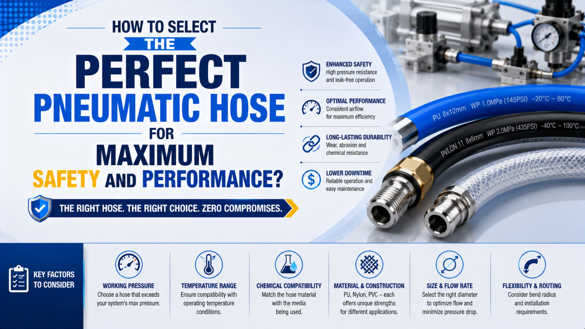
The right pneumatic hose is the one whose complete installed assembly meets the application’s pressure, temperature, media, flow, motion, connection, and inspection requirements. Start with measured duty, then select a product series and matching ends. A color, polymer name, or burst-pressure figure can’t approve the hose by itself.
ISO 2398:2024 covers three types, three classes, and two categories of textile-reinforced rubber hose for compressed air, with scope extending to 2.5 MPa (25 bar) and, depending on classification, from -40°C to +70°C (ISO 2398:2024, 2024). Those are standard boundaries, not universal ratings for every hose.
Key Takeaways
- Select from working pressure, never burst pressure.
- ISO 2398:2024 reaches 25 bar, but the exact hose classification still governs.
- Check ID and every coupler as part of the airflow path.
- Approve chemical exposure and repeated motion from product-specific evidence.

A hose becomes a usable assembly only after its end fittings, couplers, routing, protection, and inspection criteria are specified.
Treat hose selection as seven approval gates. If one gate remains undocumented, the purchasing description isn’t complete.
Seven Inputs Define the Correct Pneumatic Hose
ISO 5774:2023 specifies four types of textile-reinforced thermoplastic hose for compressed-air applications from -10°C to +60°C (ISO 5774:2023, 2023). That narrower published temperature scope illustrates the first rule: select an exact construction against seven application inputs, not a generic label such as “thermoplastic hose.”
Build the specification from the machine outward:
| Selection input | Record before choosing a hose | Evidence to request |
|---|---|---|
| Pressure | normal, maximum regulated pressure, credible transient, vacuum if applicable | working-pressure curve at the real temperature |
| Temperature | conveyed-air temperature, ambient range, radiant or contact heat, cold start | product temperature limits and derating |
| Media | compressed-air quality, compressor oil, water, cleaners, coolant, ozone, UV | compatibility statement for tube, reinforcement, cover, and seals |
| Flow | peak demand, hose length, acceptable point-of-use pressure | ID, flow or pressure-drop data, coupler restriction |
| Motion | static bend, repeated flex, torsion, drag, vibration, reel use | minimum bend radius and model-specific dynamic-duty evidence |
| Connections | barb, crimp, reusable end, quick-disconnect, port thread | approved hose-and-end combination and assembly method |
| Maintenance | inspection interval, access, isolation, removal criteria | documented inspection and replacement plan |
A selection table is a screening record, not a substitute for the supplier’s exact datasheet. For fixed machine plumbing, also compare flexible hose with purpose-designed pneumatic tubing and fitting combinations. They solve different routing and motion problems.
The safest RFQ names a hose series, size, ends, assembled length, operating envelope, motion class, and required documentation. “Blue PU air hose, 10 mm” leaves most failure variables uncontrolled.
Working Pressure, Temperature, and Burst Pressure
ISO 2398:2024 allows a maximum working-pressure scope of 25 bar for covered reinforced-rubber classifications. By contrast, SMC’s TU polyurethane tubing lists 0.8 MPa at 20°C, 0.65 MPa at 40°C, and 0.5 MPa at 60°C (SMC TU/TIUB, accessed 2026). Use the lowest temperature-adjusted assembly limit.
The controlling limit can belong to the hose, an end fitting, a crimp, a clamp, a quick coupler, a swivel, or a port adapter. Express that assembly rule as:
Here, is the actual ambient and conveyed-air temperature, is the internal and external media exposure, and every value is the manufacturer’s allowable working pressure after applicable derating. The result is a screening ceiling, not permission to operate without the machine’s safety analysis.
Burst pressure isn’t an operating target. The SMC TU catalog separates its burst-pressure curve from maximum operating-pressure values, and OSHA requires that manufacturer safe operating pressure not be exceeded for hoses and related components in its pneumatic-tool rule. Select from the published working or operating limit, not the burst curve.
Pressure peaks matter too. Measure them at a representative point and operating state. A regulator gauge viewed while the machine is idle won’t reveal a downstream pressure collapse during simultaneous actuator motion, nor will it show a fast transient near a closing valve.
For machinery, establish the maximum credible pressure from the supply architecture and fault analysis. The separate working-pressure guide explains why component rating, regulator setting, and dynamic actuator pressure aren’t interchangeable.
Which Hose ID Preserves Cylinder Speed and Point-of-Use Pressure?
OSHA’s construction rule applies an extra source or branch-line safety-device requirement to pneumatic power-tool hoses exceeding 1/2-inch ID, and separately prohibits exceeding manufacturer safe operating pressure (29 CFR 1926.302(b)). The threshold is scope-specific, but it shows why hose ID affects both airflow and safety provisions.
Size from peak demand, not compressor nameplate flow. The air path includes:
- upstream pipe or manifold;
- isolation and preparation components;
- valve and port passages;
- quick couplers and adapters;
- hose ID and length;
- tool, nozzle, or actuator port;
- exhaust restrictions during actuator return.
The total loss is the sum of component losses at the same operating condition:
Each is the measured or supplier-published pressure drop across one component at the stated inlet pressure, temperature, and flow convention. Don’t insert liquid-service Cv equations into a compressed-air decision without a valid compressible-flow model and documented reference conditions.
The hose with the largest ID isn’t automatically best. A larger, heavier line can increase moving mass, minimum bend radius, and strain at the end fitting. Select the smallest ID that passes the pressure-at-demand test with the complete connection path, then verify that its mechanical behavior still fits the machine.
Measure pressure upstream and at the point of use during the worst repeatable demand. If the loss is excessive, test one change at a time: shorten the line, increase ID, remove an undersized coupler, enlarge a restrictive branch, or move a valve closer to the actuator. The pressure-drop troubleshooting guide helps separate supply, line, valve, and exhaust causes.
If the required passage is still unknown, use the Tube ID Calculator as a preliminary area and velocity screen.
How Do Bend Radius, Repeated Flex, and Torsion Change Selection?
SMC’s TU/TIUB polyurethane tubing catalog lists minimum bend radii from 4 to 45 mm across its metric and inch sizes, measured at 20°C (SMC TU/TIUB, accessed 2026). That range within one family shows why a universal bend multiplier or lifetime claim can’t replace exact size and motion data.
Minimum bend radius is a geometric limit under specified conditions. It doesn’t, by itself, promise a number of flex cycles. Separate the duty:
- Static routing: the hose is installed once and sees limited movement.
- Occasional repositioning: operators or maintenance move the hose intermittently.
- Repeated flex: a machine bends the same zone every cycle.
- Torsion: end points rotate the hose around its axis.
- Drag-chain or robotic motion: several bending planes, acceleration, abrasion, and controlled length interact.
- Reel service: winding, payout, tension, and connector loads repeat.
For repeated motion, give the supplier the moving geometry, bend plane, speed, acceleration, cycle rate, pressure, temperature, travel, unsupported mass, and desired service interval. Ask for evidence from the exact hose and end configuration. A laboratory result from another construction isn’t a transferable life rating.
Route the hose so bending starts away from the fitting, not at the ferrule or barb shoulder. Prevent twist during installation; add a swivel only when its pressure, flow, media, and motion ratings suit the duty. Clamps should control movement without crushing the hose or forcing a hinge at the clamp edge.
SMC measures the TU/TIUB minimum bend radius by closing a U-shaped sample at 20°C until it breaks or is crushed. That method is product-specific and static. It doesn’t establish life under repeated flex, torsion, pressure cycling, or a different temperature, so dynamic service still needs separate evidence.
How Should Chemical and Environmental Compatibility Be Verified?
ISO 8031:2020 specifies test methods for conductive, antistatic, and non-conductive rubber and plastics hoses, including continuity or discontinuity between metal end fittings (ISO 8031:2020, 2020). Electrical behavior is one environment-specific property; chemical compatibility still requires separate evidence for every exposed layer and seal.
Map the exposure paths before selecting material:
- Inside the tube: compressed-air moisture, compressor lubricant carryover, cleaning agents introduced upstream, or another process gas.
- Outside the cover: washdown chemicals, cutting fluid, coolant mist, oils, ozone, UV, welding spatter, dust, and microbial or food-zone cleaning conditions.
- At the ends: fitting plating, body material, seals, clamps, ferrules, thread sealant, and dissimilar-metal contact.
A generic “PU versus EPDM versus NBR” chart is only a shortlist. Polymer grade, compound formulation, reinforcement, cover, concentration, exposure duration, temperature, mechanical stress, permeation, and acceptance criterion can change the result.
For a chemical-exposure RFQ, identify each chemical by exact name or safety-data-sheet reference, concentration, temperature, contact type, duration, and cleaning cycle. Ask the hose manufacturer to confirm compatibility for the inner tube, reinforcement, cover, and end seals. Where uncertainty remains, conduct a controlled application test and define acceptable changes in mass, dimensions, hardness, strength, leakage, or appearance before starting it.
Compressed-air cleanliness is a separate question. The ISO 8573-1 air-quality guide explains particle, water, and oil classes; it doesn’t certify a hose compound for a chemical exposure or hygienic zone.
Compatibility has two directions. The environment can damage the hose, and the hose can release extractables, particles, or permeated media into the process. Critical applications need both questions answered.
How Should Ends and Quick Couplers Be Matched to the Hose?
OSHA requires pneumatic power tools in construction to be secured to the hose or whip by a positive means that prevents accidental disconnection (29 CFR 1926.302(b)(1)). That rule isn’t a universal machine-design prescription, but it highlights the connection as a safety boundary, not a convenient accessory.
Approve the connection as a system:
- hose ID, OD, wall, reinforcement, and hardness;
- barb, stem, ferrule, clamp, or reusable-end geometry;
- assembly tooling, insertion depth, crimp diameter, or clamp specification;
- proof or acceptance test when required;
- coupler body size, actual flow data, pressure rating, temperature, seals, and shutoff behavior;
- thread standard and sealing method;
- mechanical retention and any application-required restraint.
Don’t mix hose and ends solely because the nominal sizes match. A ferrule can over-compress one wall construction and under-compress another. A generic worm-drive clamp isn’t an automatic substitute for a specified crimp, band, or interlocking system.
Quick-coupler nominal size also doesn’t reveal the effective passage. Compare the exact coupled pair, including plug profile, and request compressed-air flow or pressure-drop data at stated reference conditions. A larger body can still contain a restrictive valve or incompatible plug.
For detailed OD-, ID-, hardness-, and connection-method checks, use the hose-to-fitting compatibility guide. In corrosive washdown or chemical plants, the corrosion-resistant fitting guide adds body, plating, seal, and mixed-metal checks.
Installation and Inspection Rules Belong in the Specification
ISO 8331:2016 is a 13-page published guideline for selecting, storing, using, and maintaining rubber and plastics hoses and hose assemblies (ISO 8331:2016, 2016). Selection is incomplete until the installation, storage, inspection, isolation, removal, and replacement rules are documented for the actual service.
Before installation, verify the hose marking and ends against the approved bill of material. Inspect for shipping damage, contamination, flattened sections, cracks, cuts, blisters, exposed reinforcement, damaged sealing surfaces, corrosion, and incorrect crimp or clamp position. Keep caps in place until the clean assembly is ready to connect.
During routing:
- stay at or above the product’s minimum bend radius;
- prevent torsion and avoid pulling the hose taut;
- allow length for machine travel and pressure-related movement where the manufacturer identifies it;
- protect against edges, hot surfaces, spatter, traffic, snagging, crushing, and abrasion;
- support the assembly without concentrating load at an end fitting;
- keep disconnects accessible and prevent trip or aisle hazards.
The hose organization and workplace-safety guide covers reels, routing zones, aisle control, and line identification in more detail.
Set inspection frequency from risk and service severity. CCOHS tells pneumatic-tool users to check hoses regularly for cuts, bulges, abrasions, or other damage and to tag and replace defective hoses immediately (CCOHS, updated 2025). For production machinery, translate that principle into a documented interval and removal criteria based on motion, exposure, access, and failure consequence.
Depressurize and control stored energy before maintenance. Don’t search for leaks with bare hands, retighten a live connection, tape over cover damage, or assume that an outer sleeve restores pressure integrity. If a hose has kinked, pulled at an end, exposed reinforcement, blistered, cracked, become abraded beyond the manufacturer’s limit, or failed inspection, isolate it and apply the approved replacement process.
What Should Be Recorded on the RFQ and Acceptance Sheet?
CCOHS’s pneumatic-tool guidance calls for the correct hose and fitting diameter and rating, and states a minimum working pressure of 1035 kPa (150 psig) or 150% of maximum system pressure, whichever is higher, within that tool-safety context (CCOHS, updated 2025). Don’t transfer that multiplier blindly; record the governing application rule and exact product rating.
A procurement-ready specification should include:
| RFQ field | Required entry |
|---|---|
| Function | machine circuit, portable tool, reel, robot, drag chain, washdown, or other duty |
| Hose | manufacturer, series, size, construction, color if identification is needed |
| Pressure | normal, maximum, transient basis, vacuum, applicable design rule |
| Temperature | media and ambient minimum/maximum, hot-surface or radiant exposure |
| Media | air quality plus every internal and external chemical |
| Flow | peak demand, length, required point-of-use pressure, reference conditions |
| Motion | bend geometry, travel, speed, acceleration, torsion, cycles, abrasion |
| Ends | exact end, ferrule/clamp, coupler/plug, seal, thread, assembly method |
| Safety | isolation, restraint or safety device where required, guarding and route protection |
| Verification | certificates, marking, dimensional check, leakage/pressure test, flow test |
| Maintenance | inspection interval, retirement criteria, approved replacement |
For acceptance, compare the delivered layline and end part numbers with the order, verify assembled length and orientation, inspect workmanship, and perform the specified leak or pressure test under controlled conditions. If flow performance is critical, record point-of-use pressure during the agreed demand cycle. That creates a baseline for troubleshooting later.
In our experience, the most useful acceptance record is simple: one approved assembly part number, one operating envelope, one test condition, and one replacement rule. That record makes a future substitution visible before a visually similar hose enters service.
Pneumatic Hose FAQs: What Should Buyers Ask?
ISO 2398:2024 covers reinforced rubber compressed-air hose up to 25 bar, whereas ISO 5774:2023 defines four thermoplastic hose types over a -10°C to +60°C scope. The difference answers the first buyer question: no material family or standard number replaces the exact construction, classification, size, ends, and service conditions.
Can I select a pneumatic hose from burst pressure?
No. Select from the manufacturer’s allowable working pressure for the exact hose and end assembly at the real temperature and media condition. Parker explicitly describes burst pressure as a manufacturing-test value, not permission to operate above maximum working pressure. Include credible transients and the machine’s safety requirements before approving the rating.
Is the published minimum bend radius enough for repeated flexing?
No. Minimum bend radius is a geometric product limit under stated conditions, not a universal cycle-life promise. For repeated motion, provide the supplier with bend geometry, travel, rate, acceleration, pressure, temperature, torsion, abrasion, and required service interval. Request evidence for the exact hose size and end configuration.
Can one chemical compatibility chart approve the hose?
No. A chart can shortlist materials, but final approval must cover the exact inner tube compound, reinforcement, cover, end materials, and seals. State chemical identity, concentration, temperature, duration, and whether exposure is internal, external, intermittent, or continuous. Critical uncertainty needs a defined application test before release.
Should the quick coupler be the same nominal size as the hose?
Nominal size alone isn’t enough. Match the plug profile, seals, working-pressure and temperature ratings, media, shutoff behavior, mechanical retention, and effective airflow of the coupled pair. Check published compressed-air pressure-drop data, then measure point-of-use pressure during peak demand because the hose, ends, valve, and coupler act together.
Sources and technical references
- ISO 2398:2024, Rubber hoses, textile-reinforced, for compressed air. Accessed 2026-07-27.
- ISO 5774:2023, Plastics hoses, textile-reinforced types for compressed-air applications. Accessed 2026-07-27.
- ISO 8031:2020, Determination of electrical resistance and conductivity. Accessed 2026-07-27.
- ISO 8331:2016, Guidelines for selection, storage, use and maintenance. Accessed 2026-07-27.
- OSHA 29 CFR 1926.302, Power-operated hand tools. Accessed 2026-07-27.
- CCOHS, Powered Hand Tools: Pneumatic Tools, Basic Safety. Updated 2025-08-04; accessed 2026-07-27.
- SMC, TU/TIUB Polyurethane Tubing. Accessed 2026-07-27.