

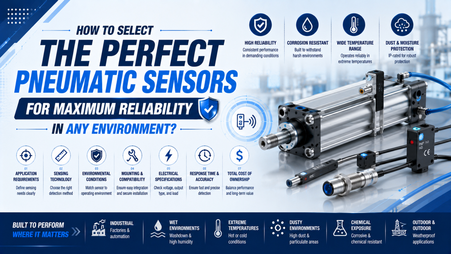
Pneumatic sensor selection is the process of matching the signal a machine must trust with a sensing principle, electrical interface, environment, installation, and acceptance test. Define whether the controller needs endpoint confirmation, measured position, a pressure threshold, or a flow value. An IP code or fast response figure alone cannot prove reliability.
Key Takeaways
- Select the measurement job before choosing a sensor family.
- Verify voltage, output topology, leakage current, connector, and PLC thresholds together.
- Treat IP, chemicals, temperature, vibration, EMC, and hazardous-area approval as separate requirements.
- Approve the sensor only after testing the installed signal under production conditions.
In this guide
- Start with the signal the machine must trust
- Match the sensor type to the measurement job
- Match the electrical interface to the PLC
- Qualify the complete operating environment
- Specify speed, accuracy, and calibration
- Commission the installed sensing chain
Start With the Signal the Machine Must Trust
An SMC auto-switch guide lists reference hysteresis of 2 mm or less for covered reed switches and 1 mm or less for covered solid-state switches, while warning that environment can change both values. Those model-specific limits show why selection must begin with the required machine signal, not a generic “sensor” label (SMC Auto Switch Guide, accessed 2026).
A sensor cannot be reliable if it measures the wrong condition. Before opening a catalog, write one sentence that completes this statement:
The controller must know ______ within ______ because ______.
“Cylinder extended within 300 ms so the conveyor can restart” is a useful requirement. “Need a reliable sensor” is not. The first statement identifies a state, timing window, and consequence. Those details guide the sensor family and the validation method.
Separate the four common sensing jobs:
| Machine question | Required signal | Typical device family | What it does not prove |
|---|---|---|---|
| Did the piston reach a defined zone? | Discrete ON/OFF | Reed or solid-state magnetic cylinder switch | Tooling position or clamp force |
| Did the moving assembly reach the process datum? | Discrete or measured external position | Inductive proximity sensor, encoder, LVDT, or other position sensor | Internal piston position unless mechanically linked |
| Is air pressure above, below, or inside a permitted band? | Discrete threshold or analog pressure | Mechanical or electronic pressure switch/sensor | Flow rate or cylinder force at the load |
| Is air flow inside the required range? | Instantaneous or accumulated flow | Thermal or other gas-compatible flow sensor | Pressure stability at a remote actuator |
For a detailed comparison of endpoint, zone, and continuous feedback, use the pneumatic cylinder position sensing guide. If the requirement is specifically about reed, Hall, or MR switch behavior, the cylinder switch operation guide covers that narrower choice.
The process datum matters more than the sensor’s mounting convenience. A switch may report that the piston magnet entered its sensing window while a loose coupling, worn guide, flexible bracket, or workpiece variation leaves the tooling out of position. If the process depends on the carriage or clamp, sense or verify that element.
Match the Sensor Type to the Measurement Job
Festo’s SDE5 family illustrates why a sensor category is not a specification: covered variants list ±0.3% full-scale repeatability, up to ±0.5% switching-output accuracy, and IP40 protection. A device may measure pressure well yet still be wrong for washdown, analog feedback, or fast fault detection (Festo SDE5 Data Sheet, 2020).
Choose a family only after defining the target and output. Then select the exact part number from the manufacturer’s compatibility and performance data.
Magnetic Cylinder Switches
A magnetic cylinder switch is a device that detects the field from a magnet built into the piston. It is compact and useful for end-position or zone confirmation, but the switch must match the cylinder, magnet, slot, bracket, and mounting orientation. A housing that fits the groove is not proof of magnetic compatibility.
Reed switches use mechanical contacts. Solid-state models use a magnetic sensing element and an electronic output. The choice affects bounce, leakage current, voltage drop, switching load, shock rating, and wiring. It does not change the fundamental limitation: a discrete switch reports a sensing zone, not continuous piston position.
External Proximity and Position Sensors
An external inductive sensor detects a metal target on a carriage, stop, jaw, or fixture. This is useful when the true process datum is outside the cylinder or when magnetic sensing is unsuitable. It requires a repeatable target, a rigid bracket, adequate sensing margin, and protection from impact or contamination.
Continuous sensors such as LVDTs, magnetostrictive devices, linear encoders, or programmable magnetic position sensors serve a different job. They provide a measured value across part of the stroke. If the controls require that level of feedback, define range, resolution, repeatability, update rate, output format, mounting error, and the machine-level acceptance tolerance.
Pressure Switches and Sensors
A pressure switch is a device that changes output at a defined pressure threshold. An analog pressure sensor reports a value instead. Those jobs may share the same housing, but they create different PLC requirements and diagnostics.
Select the pressure range so normal operation uses a meaningful part of the measuring span without exceeding proof-pressure limits. Then check whether the sensor sees clean compressed air, vacuum, a lubricated line, condensate, or another compatible medium. A product rated for compressed air is not automatically compatible with every gas or liquid.
Hysteresis also needs an application value. Too little can create repeated switching around a noisy threshold. Too much can hide a meaningful pressure change. Set the threshold and hysteresis from measured normal variation and the process fault limit, then verify both rising and falling pressure.
Flow Sensors
Flow sensors may report instantaneous flow, accumulated consumption, or a discrete limit. Specify the gas, rated range, reference condition, permitted pressure and temperature, straight-run or mounting requirements, response setting, and output.
Do not select a flow sensor only because its port thread matches the tube. An oversized range can reduce useful resolution near the operating point. An undersized body can add pressure loss or saturate its measurement. If the real question is cylinder timing rather than air consumption, investigate valve, tubing, exhaust, load, and chamber response as well. The article on transient pressure response in long-stroke cylinders explains that broader timing chain.
How Should the Electrical Interface Match the PLC?
One current SMC D-MH2 magnetic switch specifies an 18–30 VDC supply, 40 mA maximum load current, 0.5 mA maximum leakage current, and 5 ms maximum operating time. Those values belong to that model, but they expose the checks every PLC interface needs: voltage, topology, thresholds, timing, protection, and pinout (SMC D-MH2 Manual, accessed 2026).
Electrical compatibility should be checked before purchase, not during startup. Record the PLC input module and sensor output on the same review sheet.
| Interface item | What to verify | Failure when it is missed |
|---|---|---|
| Supply | Voltage range, polarity, current demand, power-up delay | No output, intermittent startup, or device damage |
| Output topology | PNP, NPN, push-pull, two-wire, relay, analog, or communication | Sensor LED changes but PLC input does not |
| Switching function | Normally open/closed, threshold, window, or latch behavior | Program logic is inverted or misses the fault state |
| Load limits | Maximum current, minimum load, inrush, inductive protection | Contact wear, output failure, or unreliable ON state |
| OFF-state behavior | Leakage current and PLC guaranteed OFF threshold | Input remains ON after the sensor releases |
| ON-state behavior | Internal voltage drop and PLC guaranteed ON threshold | Input never reaches a valid ON state |
| Connector | M8/M12 size, pinout, keying, cable exit, shield requirement | Wrong wiring, poor sealing, or service mismatch |
| Timing | Sensor response, input filter, scan/task rate, debounce | Short event is missed or one event becomes several |
Two-wire switches share current with the load. That makes leakage current and internal voltage drop especially important. Three-wire sensors separate supply and output, but PNP and NPN still need the correct input common. Analog outputs add scaling, wire-break behavior, resolution, shielding, and grounding questions.
What if the sensor LED is stable while the PLC input flickers? Start with the electrical path: connector, supply, common, output loading, cable routing, input threshold, and filter. If the LED and PLC agree but the tooling is wrong, move the investigation to the magnet, mounting, mechanics, and pneumatic motion.
Treat replacement approval as two keys. The mechanical key covers target, cylinder, magnet, slot, bracket, range, and physical fit. The electrical key covers topology, voltage, current, pinout, PLC thresholds, and timing. A replacement is equivalent only when both keys match.
Environmental Protection Is More Than an IP Number
IEC 60529 uses a two-character IP code for enclosure protection, while ISO 20653:2023 applies IP codes to road-vehicle electrical equipment and includes its own test framework. Neither standard proves chemical resistance, hygienic design, cable-flex life, EMC immunity, or safe use in an explosive atmosphere (IEC 60529, 2013; ISO 20653:2023, 2023).
Use the IP code for the ingress question it answers. Then qualify the remaining exposure paths independently.
| Exposure | Evidence to request | Why IP alone is insufficient |
|---|---|---|
| Water and dust | Exact IP code, test standard, connector state, installation limits | A rating may depend on a fitted connector, plug, or mounting orientation |
| Coolant, detergent, oil, or acid | Housing, seal, potting, cable-jacket compatibility and concentration/temperature limits | Ingress resistance does not prove chemical compatibility |
| Temperature | Ambient, medium, storage, thermal-cycle, condensation, and heat-source limits | A stainless housing does not raise the electronics or cable rating |
| Vibration and shock | Model-specific test values, bracket design, tightening torque, cable support | A sensor can move or its lead can fatigue without losing ingress protection |
| Welding and magnetic fields | Approved field-resistant model, current-path review, cable protection, installed test | Standard magnetic switches may change state or lose margin near strong fields |
| EMC and surge | Applicable product standard, named immunity tests, cable configuration, grounding instructions | “EMI protected” does not identify a disturbance or test level |
| Hazardous atmosphere | Required regional and zone/class approval for the exact model | IP is not explosion-protection certification |
| Hygiene | Cleanable geometry, material declarations, food-contact requirements, installation and sanitation validation | Washdown resistance is not hygienic design |
SMC’s current auto-switch instructions give a useful warning: covered switches may satisfy IEC IP67 specifications yet still be unsuitable for continual water splash or spray. The same document warns that coolant, cleaning solvent, oil, chemicals, temperature cycles, iron particles, and external fields can cause malfunction or material degradation (SMC D-MH2 Manual, accessed 2026).
For washdown, write the real cleaning envelope into the RFQ: spray direction, pressure, temperature, duration, frequency, chemical name, concentration, rinse, connector arrangement, and expected service life. “IP67 required” leaves most of that exposure undefined.
Welding cells need another branch of review. A cylinder magnetic switch and a weld-field-immune inductive proximity sensor do not detect the same target. The welding-environment cylinder sensor guide explains that distinction and the required installed qualification.
How Fast and Accurate Does the Sensor Need to Be?
Current SMC flow-switch tables cover rated ranges from 0.01 L/min to 12,000 L/min across several sensor families and fluids. That span makes a single “typical” accuracy or response value meaningless. Required performance must be tied to the selected model, range, fluid, reference condition, filter setting, and process event (SMC Flow Sensor Product Variations, accessed 2026).
Start from the event the controller must detect. A pressure switch used for compressor supervision may tolerate a slower filtered signal. A sensor protecting a fast fixture may not. Write the shortest event duration, permitted detection delay, acceptable false-trip rate, and the action that follows.
The complete detection delay includes more than the sensing element:
- The physical pressure, flow, magnet, or target must change at the sensing point.
- The sensor needs time to measure, filter, and change its output.
- The PLC input filter must accept the state.
- The controller must scan or update the input.
- The program must execute the relevant logic and output.
That chain explains why replacing a 5 ms sensor with a 1 ms model may not improve a machine whose input filter is 20 ms or whose pneumatic event reaches the sensor late. Measure the installed timestamps before paying for speed.
Accuracy needs the same discipline. Separate these terms:
- Accuracy: closeness to the reference value under stated conditions.
- Repeatability: closeness of repeated results under the same conditions.
- Resolution: the smallest displayed or reported increment.
- Hysteresis: difference between operate and release behavior.
- Temperature characteristic: change across the specified temperature range.
- Response time: delay defined by the manufacturer’s test and output criteria.
Festo’s SDE5 data also shows why output type matters: covered switching variants list up to ±0.5% full-scale accuracy, while covered analog variants list different accuracy figures and conditions. Do not transfer one output’s value to another configuration (Festo SDE5 Data Sheet, 2020).
Use Risk-Based Calibration and Verification
There is no defensible universal calibration interval for every pneumatic pressure or flow sensor. Start with the manufacturer’s instructions and the site’s quality requirements. Then adjust the interval using observed drift, process criticality, environmental severity, duty cycle, maintenance history, and the consequence of an incorrect reading.
Record both as-found and as-left results. If a device repeatedly remains well inside tolerance, the quality system may support a longer interval. If it drifts, gets contaminated, or experiences mechanical damage, shorten the interval and correct the cause rather than merely recalibrating more often.
For discrete cylinder switches, “calibration” is often the wrong word. The practical task is mounting-position adjustment and functional verification from both approach directions under production motion. The guide on internal piston magnet design and sensor accuracy explains why field margin and mechanical position must remain separate.
What Should Commissioning Prove Before Production?
SMC’s D-MH2 manual gives a 40 mm minimum separation for multiple magnet-equipped cylinders unless the actuator series specifies another value. That is a useful commissioning example, not a universal rule: the installed machine must still be tested with real load, speed, temperature, neighboring devices, power switching, and cable movement (SMC D-MH2 Manual, accessed 2026).
Commissioning should prove the signal at the controller and the process result at the machine. A bench test proves only part of the chain.
Before Power-Up
- Record the sensor, cylinder or process connection, bracket, cable, connector, and PLC input part numbers.
- Confirm supply voltage, topology, pinout, common, load, scaling, and software configuration.
- Check mounting torque, sensing position, cable bend radius, strain relief, sealing, and service clearance.
- Verify that the sensor’s medium and environmental ratings match the documented exposure.
- Define expected ON, OFF, analog, communication, and fault states before testing.
During Functional Testing
Cycle the machine first at controlled speed, then at production speed and load. Observe the local indicator and raw PLC input separately. For analog devices, compare the controller value with a traceable reference at several points across the working range. For discrete devices, approach the switching point from both directions and record the stable operating window.
Challenge the conditions that can reduce margin:
- Minimum and maximum permitted supply pressure
- Cold start and normal operating temperature
- Slow and fast cylinder motion
- Adjacent cylinders, solenoids, drives, welders, and normal power switching
- Cable and connector movement
- Air dump, emergency stop, power cycle, and restart
- Normal contamination or cleaning state
Could the controller distinguish a failed sensor from a valid process state? Test open circuit, short circuit, out-of-range analog values, contradictory end switches, timeout, and lost communication where the architecture supports those diagnostics. A normal process sensor does not become safety-rated merely because the PLC checks it twice.
Use four observations during troubleshooting: local sensor indication, raw controller input, pneumatic state, and tooling state. Those observations divide a vague “sensor fault” into electrical, sensing, pneumatic, or mechanical branches. The magnetic-field decay versus reed-switch failure guide applies the same evidence-first approach to cylinder switches.
RFQ and Release Checklist
Send the following before requesting a final sensor selection:
| Requirement group | Information to provide |
|---|---|
| Measurement job | Target, normal state, fault state, range, threshold, hysteresis, and required output |
| Machine dynamics | Minimum event duration, cycle rate, speed, response budget, and controller timing |
| Pneumatic conditions | Medium, pressure, flow range, temperature, air quality, pulsation, and contamination |
| Electrical interface | Supply, PNP/NPN/two-wire/analog/IO-Link, PLC input model, connector, and cable length |
| Mechanical interface | Cylinder and magnet, slot or bracket, process target, orientation, space, and service access |
| Environment | IP need, cleaning, chemicals, temperature, vibration, weld field, EMC, UV, and hazardous-area requirements |
| Acceptance | Reference equipment, test points, repetitions, pass limits, fault tests, and required records |
Keep the completed sheet with the machine documentation. It turns future replacement work from visual matching into an equivalence review.
Pneumatic Sensor Selection FAQs
IEC 60529 distinguishes six numbered solid-ingress levels after zero and nine numbered water-ingress levels after zero, but the code answers only an enclosure question. These four FAQs apply that boundary to sensor selection, response, calibration, and washdown without treating one IP number or one catalog timing value as a reliability guarantee (IEC 60529, 2013).
Should I choose a reed switch or a solid-state cylinder switch?
Choose from the exact cylinder compatibility list and electrical requirements. Reed models use mechanical contacts; solid-state models use electronic sensing and outputs. Compare load, leakage, voltage drop, response, shock, magnetic environment, slot, and PLC input. Neither family is automatically better. The approved part is the one that meets the installed requirements and acceptance test.
Is IP67 enough for a washdown application?
Not by itself. IP67 addresses defined dust and temporary-immersion tests, but it does not prove resistance to hot spray, cleaning chemicals, repeated thermal cycling, cable flex, or hygienic requirements. Check the exact manufacturer restrictions, connector condition, cleaning envelope, housing and seal materials, and installed orientation before approving a washdown sensor.
How do I know whether sensor response time is fast enough?
Compare the shortest process event with the complete detection chain: physical transport, sensor response and filtering, PLC input filter, scan or task update, program logic, and output action. Test the installed chain with production-like events. A faster catalog value provides little benefit when another stage controls the total delay.
How often should pneumatic pressure and flow sensors be calibrated?
Use the manufacturer’s instructions and the site’s quality system as the starting point. Set the interval from process risk, observed drift, duty cycle, contamination, environmental severity, and failure consequence. Record as-found and as-left data. Repeated drift calls for root-cause correction as well as a shorter verification interval.
Sources and technical references
- SMC Auto Switch Guide. Cylinder auto-switch terminology, hysteresis, operating range, electrical interface, and environmental precautions. Retrieved 2026-07-27.
- SMC D-MH2 2-in-1 Auto Switch Manual. Model-specific electrical, timing, mounting, separation, and environmental requirements. Retrieved 2026-07-27.
- Festo SDE5 Pressure Sensor Data Sheet. Model-family pressure, accuracy, output, medium, timing, and environmental data. Retrieved 2026-07-27.
- SMC Flow Sensor Product Variations. Current flow-switch family ranges, compatible fluids, outputs, and selection characteristics. Retrieved 2026-07-27.
- IEC 60529. Degrees of protection provided by enclosures, IP Code. Retrieved 2026-07-27.
- ISO 20653:2023. Road-vehicle electrical equipment IP codes and verification tests. Retrieved 2026-07-27.