

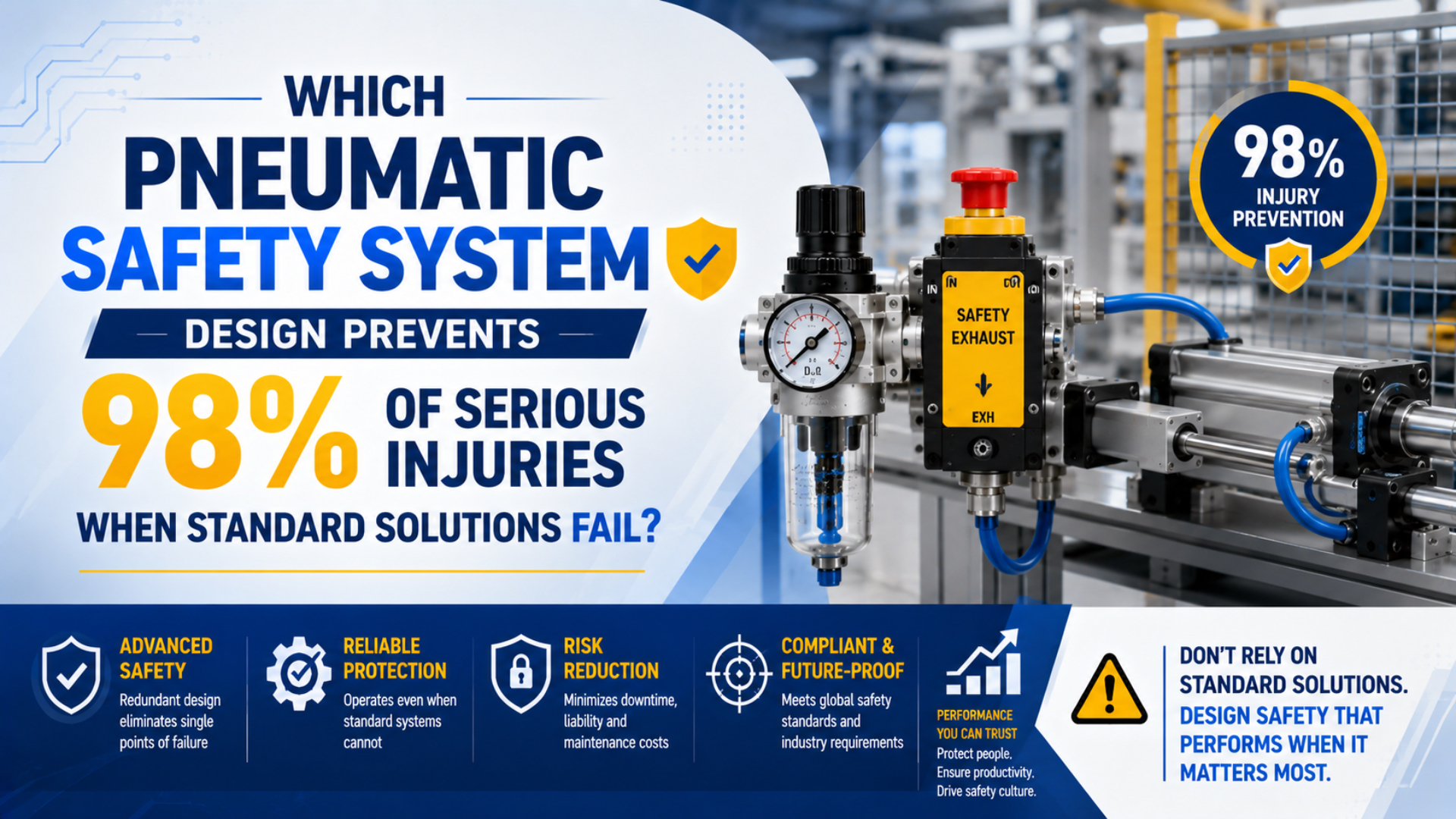
No pneumatic safety system design can substantiate a universal 98% reduction in serious injuries. A defensible design starts with the machine hazard, defines the required safe state, selects a suitable control architecture, and validates the complete safety function. Fast valves, redundancy, diagnostics, load holding, and lockout can all matter, but they solve different problems.
OSHA estimates that compliance with its lockout/tagout standard prevents 120 fatalities and 50,000 injuries each year. That figure applies to hazardous-energy control across industries, not to one pneumatic circuit or valve arrangement (OSHA Lockout/Tagout Fact Sheet, 2022).
Key Takeaways
- No standard supports a universal 98% injury-reduction promise.
- Define the safe state before selecting valves or rod locks.
- Use total stopping time, not valve response alone, for separation distance.
- Validate the installed safety function and keep maintenance LOTO separate.
Can Any Pneumatic Safety System Design Guarantee 98% Injury Prevention?
OSHA attributes an estimated 120 prevented fatalities and 50,000 prevented injuries per year to compliance with its hazardous-energy standard, but it does not assign a 98% result to pneumatic safety design. No ISO or IEC machinery-safety standard supplies that universal percentage (OSHA Lockout/Tagout Fact Sheet, 2022).
Treating a percentage as the design target hides the variables that matter. Injury risk depends on the hazard, exposure, possible severity, access, operating mode, human behavior, machine response, component reliability, and effectiveness of risk-reduction measures. A figure derived from one plant or machine would not transfer automatically to another.
Risk reduction is the process of lowering risk through inherently safe design, safeguarding and complementary protective measures, and information for use. ISO 12100 describes this as an iterative process rather than a product-selection shortcut (ISO 12100:2010).
Ask a measurable question: does the machine reach and maintain its defined safe state before a person can encounter the hazard, including after the faults the selected architecture is required to tolerate? Calculations, component data, tests, and records can answer that.
Make the resulting claim narrow. For example: “Opening Guard A causes hazardous clamp motion to stop before the calculated separation distance is crossed, and a detected output fault prevents automatic restart.” That is auditable. “Our system prevents 98% of injuries” is not.
Defining the Safety Function Before Choosing a Valve
Define each safety function before selecting a valve. ISO 12100:2010 is a 77-page machinery-safety standard, confirmed as current in 2022, that starts with hazard identification and iterative risk reduction. The function’s demand, safe state, fault behavior, and acceptance criteria belong in the specification (ISO 12100:2010).
A safety function is a specified machine response that reduces risk when a defined event occurs. “Install a monitored dump valve” is a component instruction, not a complete safety function. The specification must state what initiates the response, what hazardous behavior must stop or be prevented, and how the result will be verified.
Start with six questions:
- What motion, pressure, gravity load, vacuum, spring force, or stored energy can cause harm during operation, shutdown, power loss, maintenance, and recovery from an interruption?
- Who can be exposed, in which operating and maintenance modes?
- What physical condition constitutes the safe state?
- How quickly must that state be reached and how long must it be maintained?
- Which faults must be detected or tolerated?
- What reset and restart behavior prevents a new hazard?
Safe states can differ across one machine. A horizontal clamp may need pressure removed. A vertical axis may need its load supported before air is exhausted. A gripper may need to retain a part until a safe deposit sequence finishes. Why assume that “air off” always means “safe”?
| Hazard condition | Possible safe-state requirement | Evidence needed |
|---|---|---|
| Horizontal cylinder can crush an operator | Stop motion, block supply, reduce trapped pressure | total stopping time and residual-pressure test |
| Vertical load can fall when pressure disappears | Hold or mechanically support the load before exhausting | rated holding data and installed load test |
| Vacuum gripper can drop a part | Maintain grip or move the part to a controlled location | loss-of-supply test and load monitoring |
| Spring-return actuator moves during venting | Control or restrain the return motion | travel, force, and access-zone verification |
| Technician enters for service | Isolate energy, lock it out, dissipate or restrain stored energy | machine-specific LOTO procedure and isolation check |
The two-hand safety-control circuit guide shows how one input technology fits into this larger input, logic, output, and validation chain.
Why Is a Universal 15 to 50 ms Valve Target Unsafe?
Valve response alone cannot define a safe separation distance. ISO 13855:2024 is a 72-page standard that bases safeguard positioning on overall stopping performance. Sensor, logic, output, pressure decay, actuator motion, load behavior, and mechanical run-down all contribute to the application-specific result (ISO 13855:2024).
Valve shift time is only one interval. One valve may move in 20 ms while a large downstream volume takes much longer to depressurize. A cylinder may also continue moving because of trapped pressure, inertia, gravity, an external spring, or stored mechanical energy.
For many ISO 13855 applications, the general separation-distance relationship is:
Here, is the minimum separation distance in millimeters, is the applicable human approach-speed parameter in millimeters per second, is the complete stopping performance in seconds, and is the intrusion or reach allowance in millimeters. Exact values and conditions depend on the safeguard, approach, machine standard, and application.
Represent the complete time budget as:
Each term is a worst-case contribution from detection through final cessation of the hazardous function. Manufacturer response-time data can support the first calculations, but installed stopping performance still needs measurement. Rockwell’s 2026 safety application guidance likewise states that the final calculation must use the specific safety system and measured machine stop time (Rockwell Automation, 2026).
Measure the signal and the physical outcome on one time base:
- record the safeguard demand;
- capture safety-controller input and output transitions;
- monitor final-element feedback, when provided;
- measure pressure at the relevant actuator ports;
- record the last hazardous motion, not merely valve spool movement;
- repeat under the worst approved load, pressure, temperature, operating mode, exhaust restriction, and expected contamination state likely to slow the physical response.
If pressure decay is the safety objective, define the downstream pressure that constitutes the safe condition and the time allowed to reach it. If the objective is load holding, pressure decay may be secondary. The acceptance limit must follow the safety function.
For axes that continue moving after energy removal, the emergency-stop dynamics guide examines inertia, external loads, and the difference between de-energizing and physically stopping motion.
Selecting PL or SIL for Machinery Safety
Choose the applicable framework before calculating reliability. ISO 13849-1:2023 contains 152 pages and covers high-demand or continuous safety controls using pneumatic and other technologies; IEC 62061:2021 provides a machinery method based on SIL. Project requirements determine which method governs (ISO 13849-1:2023; IEC 62061:2021).
Performance Level, or PL, is the ISO 13849 measure used to describe a safety-related control system’s ability to perform a safety function under foreseeable conditions. Safety Integrity Level, or SIL, is the corresponding integrity concept used by IEC 62061 for machinery safety-related control systems.
Neither label belongs to a valve in isolation when the claim concerns the complete machine. Certification of a final element can supply useful failure data and architectural features, but the achieved PL or SIL also depends on the input devices, logic, interfaces, diagnostics, common-cause controls, application conditions, and validation.
Do not calculate both frameworks and publish whichever result appears more favorable. Select the method required by the project’s regulatory route, machine standard, customer specification, and engineering process. Document assumptions, subsystem boundaries, mission time, demand rate, component reliability data, fault exclusions, and diagnostic coverage.
For calculation details, the ISO 13849 pneumatic safety-circuit guide covers PLr, Category, MTTFd, DCavg, CCF, and SISTEMA. This article stays at the system decision level: what must the pneumatic output actually do, and how will the installed machine prove it?
How Should the Pneumatic Safe State Be Chosen?
Select the safe state from the hazard analysis, not from a default exhaust command. ISO 14118:2017 is an 11-page standard addressing unexpected startup from pneumatic supply, gravity, springs, and external influences, and it does not assign PL or SIL to a specific machine (ISO 14118:2017).
A pneumatic safe state is the physical condition in which the identified pneumatic and mechanically stored energies no longer create unacceptable risk. It may require one action or a coordinated sequence.
Common choices include:
- Block and exhaust: isolate supply and vent a non-load-bearing circuit.
- Hold before exhausting: engage a qualified load-holding or mechanical restraint, confirm engagement, and then vent the appropriate volume.
- Prevent pressure loss: retain pressure temporarily when loss of vacuum or gripping force would drop a part, while monitoring the stored energy.
- Controlled return: move an actuator to a verified safe position before isolating power.
- Mechanical support: block an elevated member with a restraint qualified for its mass, load direction, access conditions, and foreseeable maintenance activity so the safe condition does not depend on compressed air or a control signal.
Avoid treating “dual-pressure locking mechanism” as a universal safety-device category. Specify the actual mechanism: spring-applied rod lock, dynamic brake, pilot-operated check arrangement, counterbalance method, external mechanical block, or another validated restraint. Static holding and emergency braking are different duties.
Use the safety exhaust valve integration guide when pressure reduction is the required result. For retained loads, the pneumatic rod-lock guide explains why static holding capacity does not automatically prove dynamic stopping capability.
The latching-cylinder guide covers another retained-position approach, but its product limits still need to be evaluated within the complete safety function.
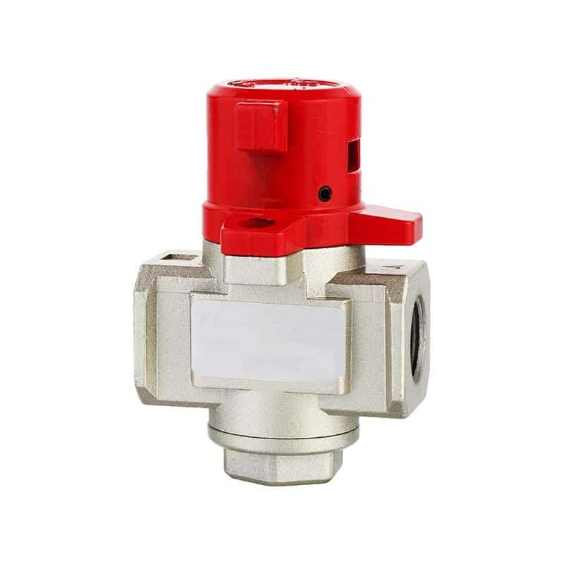
A lockable venting valve can support pneumatic energy isolation, but the complete procedure must also address trapped pressure, gravity loads, other energy sources, verification, and restart.
What Do Redundancy and Diagnostics Need to Prove?
Redundancy must survive the faults claimed in the safety analysis. ISO 13849-1:2023 applies to a 152-page methodology covering pneumatic, mechanical, electrical, hydraulic, and software elements. Two valves that share one vulnerable supply, command, or exhaust path may still fail together (ISO 13849-1:2023).
Redundancy helps only when one channel can still perform the required response after a relevant fault in the other. Diagnostics help only when they detect the faults claimed in the safety analysis and cause a defined reaction before accumulated faults defeat the function.
What could disable both channels? Contaminated air, frozen moisture, one undersized silencer, shared electrical power, incorrect maintenance, a common controller output, mechanical binding, or a mounting failure may bypass nominal channel independence. Physical separation alone doesn’t settle common-cause failure.
In our experience reviewing pneumatic safety concepts, the fastest way to expose weak redundancy is to trace energy and commands instead of counting components. We ask what supplies both channels, what prevents both from exhausting, what feedback proves the physical state, and which single maintenance error can affect them together.
Document the following in the engineering file:
- the hazard, initiating event, exact safety function, physical safe state, response-time limit, and required PLr or SIL;
- the architecture and subsystem boundaries;
- manufacturer B10d, MTTFd, failure-rate, usage, and environmental data together with every applied assumption;
- diagnostic coverage, test rate, fault response, and the physical quantity each diagnostic observes or cannot observe;
- common-cause measures, fault exclusions, and their justification;
- expected cycle rate, mission time, and maintenance constraints;
- the machine response to a detected fault, the conditions for reset, and the evidence needed before production can resume.
Spool-position feedback confirms spool position, not downstream pressure or cylinder motion. A pressure switch confirms pressure at its port, not mechanical restraint. A cylinder sensor confirms piston location, not necessarily the external load. Choose feedback that is close to the safety function’s lost physical outcome.
How Should the Installed Safety Function Be Validated?
Validation must prove the specified function on the installed machine. ISO 13849-2:2012 devotes 79 pages to validation by analysis and testing of safety functions, achieved Category, and achieved Performance Level; a component certificate alone is not system evidence (ISO 13849-2:2012).
Create the validation plan before commissioning. Tie every requirement to a method, acceptance limit, test condition, responsible person, and record. If the requirement says “rapid exhaust” without naming the measured location, pressure threshold, timing reference, and worst-case volume, it is not yet testable.
| Validation target | Measurement or inspection | Representative challenge | Acceptance evidence |
|---|---|---|---|
| Stop hazardous motion | synchronized demand and motion trace | maximum approved speed and load | measured stop time within the design limit |
| Reach safe pressure | downstream pressure-time trace | largest volume and most restrictive exhaust path | threshold reached within the specified time |
| Hold a gravity load | position or displacement over time | loss of supply and relevant single faults | movement remains within the approved limit |
| Detect an output fault | feedback and safety-controller record | one output prevented from changing state | fault detected and restart inhibited |
| Prevent unexpected restart | command, reset, and actuator observation | guard closes or supply returns | no hazardous motion before deliberate reset |
| Maintain isolation for service | energy-isolation verification | trapped or reaccumulating pressure | all energy sources isolated or restrained |
Test foreseeable faults without creating uncontrolled exposure. Use suitable fixtures, exclusion zones, calibrated instruments, supported loads, and an authorized test procedure. Some faults can be simulated by disconnecting feedback or inhibiting one channel; others require analysis because physical fault insertion would be unsafe or destructive.
One successful stop is not a validation program. Repeat measurements across supply tolerance, load range, operating mode, temperature, exhaust restriction, and the component states that produce the slowest response. Record maximum observed values and the measurement uncertainty. Would the function still pass if the next stop were slightly slower?
Revalidate after a change to the valve, silencer, tubing, controller timing, software, load, guard, cylinder, rod lock, pressure setting, or test method. Calling a replacement “like for like” does not prove identical safety data or dynamic behavior.
LOTO and the Limits of Control-System Safety
LOTO governs covered servicing where hazardous energy must be controlled. OSHA 29 CFR 1910.147 explicitly includes pneumatic energy and requires isolation, treatment of stored or residual energy, and verification before work. An emergency stop or safety PLC output cannot substitute for that process (OSHA 1910.147).
Emergency-stop and guarding functions support risk reduction during operation. LOTO controls hazardous energy during covered servicing and maintenance. Pressing an emergency-stop button usually changes the control state; it may not physically isolate electrical power, pneumatic supply, accumulators, trapped chamber pressure, gravity, or springs.
OSHA’s sequence requires preparation, orderly shutdown, isolation of energy sources, application of locks or tags, control of stored energy, and verification. Pneumatic verification may include checking a pressure indicator, operating a normal control where permitted to confirm isolation, testing for trapped pressure, and confirming that elevated members are blocked or otherwise restrained.
A lockable venting valve can be one energy-isolating device. It does not identify every energy source or prove that a blocked passage cannot reaccumulate pressure. Machine-specific procedures must define the valve position, lock location, bleed points, restraint method, verification step, and restoration sequence.
OSHA also requires periodic inspection of each energy-control procedure at least annually under 1910.147(c)(6). That interval applies to the procedure inspection, not automatically to every safety-valve proof test. Component and safety-function test intervals come from the applicable standard, manufacturer data, reliability calculation, risk assessment, and observed condition.
Pneumatic Safety System FAQs: What Should Engineers Verify?
Engineers must verify three distinct outcomes. ISO 13849-1:2023 covers high-demand and continuous safety controls, ISO 14118:2017 addresses unexpected startup from multiple energy sources, and OSHA 1910.147 governs covered servicing. Control integrity, the physical safe state, and energy isolation must work as coordinated requirements.
Must an emergency-stop valve close within 50 ms?
No universal 50 ms limit applies to every pneumatic machine. The required result comes from the risk assessment, safe-state definition, and total stopping-performance calculation. Measure the complete chain from the initiating device through logic, valve response, pressure change, actuator behavior, and cessation of hazardous motion. Compare that worst-case result with the documented acceptance limit.
Does a PL e or SIL 3 valve make the complete machine compliant?
No. A component certificate describes the component within stated conditions and architectures. The complete safety function also includes sensors, logic, interfaces, pneumatic outputs, mechanical behavior, diagnostics, common-cause controls, software, installation, and validation. Designers must verify the achieved PL or SIL for the defined system boundary rather than transfer one component’s rating to the machine.
Should every pneumatic circuit exhaust when a guard opens?
No. Exhausting pressure can create a falling-load, spring-return, vacuum-loss, or uncontrolled-motion hazard. Define the safe state for each hazardous function first. Some circuits should exhaust; others may need a rod lock, mechanical support, retained pressure with monitoring, or a controlled return. Validate the complete sequence under normal and fault conditions.
Can a rod lock replace mechanical blocking or LOTO?
Not automatically. A rod lock may hold a stationary load within specified conditions, while dynamic braking, personnel protection, and energy isolation are separate duties. Confirm the exact product rating, engagement sequence, load direction, rod condition, failure behavior, and safety documentation. During covered servicing, follow the machine-specific LOTO procedure and support hazardous gravity loads as required.
How often should a pneumatic safety function be tested?
There is no universal monthly, quarterly, or annual proof-test interval for every pneumatic safety function. Use the applicable standard, reliability calculation, manufacturer instructions, operating cycles, diagnostics, environment, and risk assessment. OSHA separately requires at least annual inspection of each energy-control procedure. Revalidate whenever a change can affect the safety function or its assumptions.
Sources and technical references
- OSHA Lockout/Tagout Fact Sheet, estimated fatalities and injuries prevented, covered energy types, and worker training. Retrieved 2026-07-27.
- OSHA 29 CFR 1910.147, hazardous-energy control, stored-energy treatment, isolation verification, and periodic procedure inspection. Retrieved 2026-07-27.
- ISO 12100:2010, machinery risk assessment and iterative risk reduction. Retrieved 2026-07-27.
- ISO 13850:2015, emergency-stop function principles. Retrieved 2026-07-27.
- ISO 13855:2024, safeguard positioning and human approach. Retrieved 2026-07-27.
- ISO 13849-1:2023, design and integration of safety-related control-system parts. Retrieved 2026-07-27.
- ISO 13849-2:2012, validation by analysis and testing. Retrieved 2026-07-27.
- IEC 62061:2021, functional safety of machinery safety-related control systems. Retrieved 2026-07-27.
- ISO 14118:2017, prevention of unexpected startup from supplied and stored energy. Retrieved 2026-07-27.
- ISO 4414:2010, pneumatic-system safety requirements across design, installation, operation, and maintenance. Retrieved 2026-07-27.
- Rockwell Automation Safety Application Technique, application-specific separation distance, complete response-chain timing, machine stop-time measurement, and an explicit warning that the final calculation must use the actual installation. Retrieved 2026-07-27.