

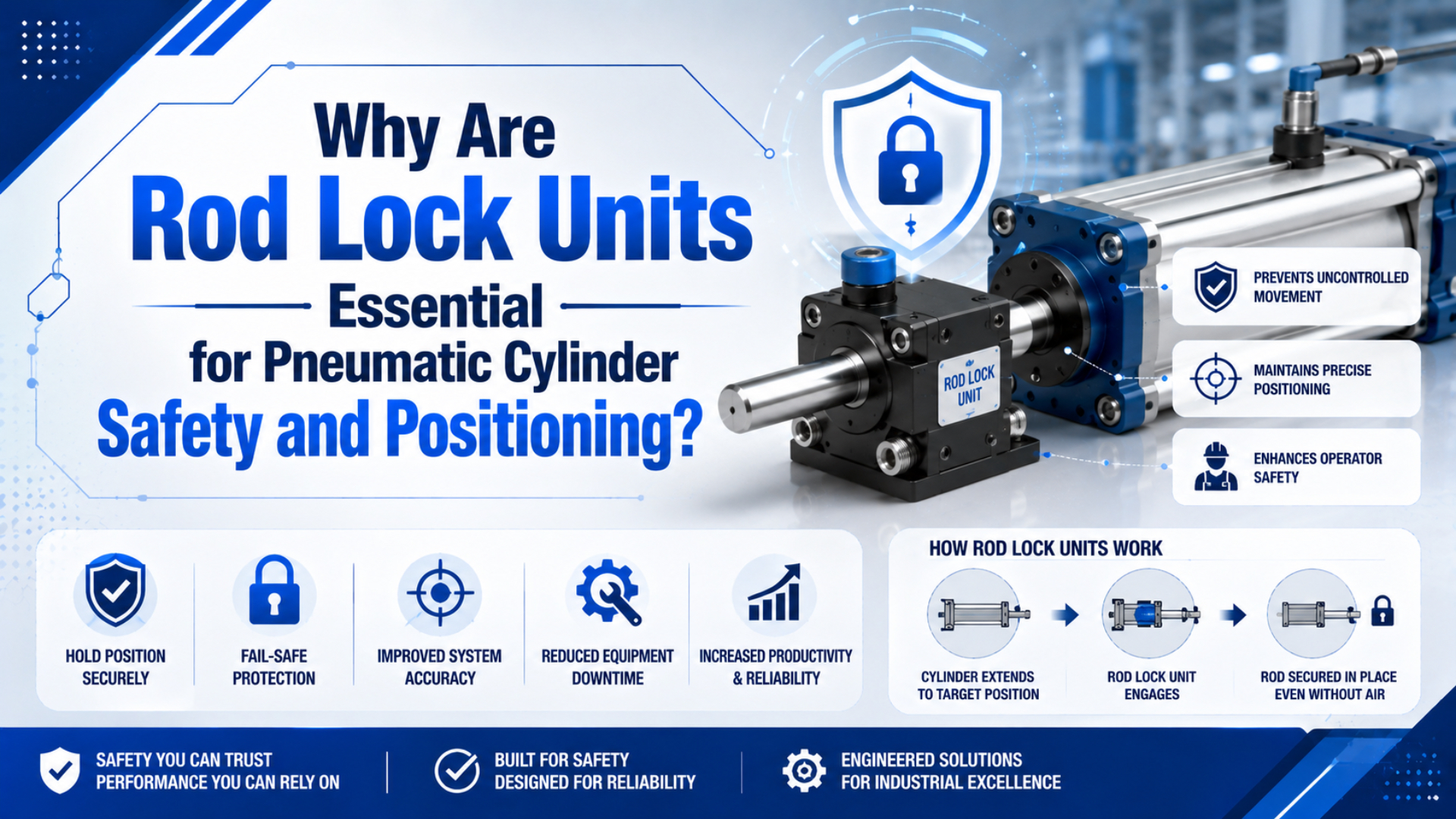
Pneumatic rod lock units are mechanical devices that resist unintended cylinder-rod movement after the release signal or air supply disappears. They add a holding state that a directional valve alone cannot provide. The important qualification is that static holding, emergency stopping, and safety-rated load retention are different duties.
A rod lock does not position the cylinder by itself. The valve, controller, sensors, and motion profile bring the rod to the target. The lock then holds that position within its permitted load, rod, pressure, and engagement conditions. A unit intended only for static clamping must not be used to arrest a moving mass.
Key Takeaways
- A spring-engaged, air-released rod lock can hold a cylinder rod after release pressure is lost.
- Static holding force does not prove that a unit can brake a moving load.
- Position repeatability depends on the complete motion sequence, not just the clamping device.
- Select from the manufacturer’s rated force and braking data, then validate the installed machine.
- A rod lock can support a safety function, but it does not replace guarding, risk assessment, or lockout/tagout.
What Do Pneumatic Rod Lock Units Actually Control?
A rod lock controls the mechanical freedom of the piston rod, not the cylinder’s direction or speed. One current Festo DFLC-63 configuration lists spring-force clamping, a 3.8 bar minimum release pressure, and 3,300 N static holding force, which shows why every performance claim must remain tied to an exact product configuration (Festo, 2026).
Most pneumatic versions use springs to apply the clamp and compressed air to release it. With adequate release pressure, the rod can move. When that pressure falls below the specified level, the springs force the clamping elements against the rod. Depending on the design, force may be transferred through wedges, rollers, locking plates, or another friction mechanism.
That function is different from four nearby concepts:
| Device or function | What it controls | What it cannot prove by itself |
|---|---|---|
| Directional valve | Airflow to the cylinder ports | That the rod cannot drift after leakage or hose failure |
| Pilot-operated check valve | Flow out of a cylinder chamber | That trapped air cannot compress, leak, or create service hazards |
| Rod lock or clamping cartridge | Mechanical movement of the rod | That moving loads may be stopped safely |
| Safety brake or certified clamping unit | Holding and, when specified, braking | That the complete machine achieves its required Performance Level |
The distinction matters most on vertical axes. Exhausting both cylinder chambers may remove pneumatic drive force while also removing the force that supported the load. A mechanical hold can prevent that drop, but only when it is selected for the actual worst-case direction and installed within its operating limits.
For a component-level explanation of spring engagement and pressure release, see how a cylinder rod lock works. This article focuses on deciding whether the lock, circuit, and validation method match the intended safety and positioning duty.
Why Is Static Holding Different from Dynamic Braking?
Static locks engage after the rod has stopped, while braking units are designed to absorb motion within stated limits. Parker’s current P1D documentation lists static lock forces from 600 to 7,000 N and dynamic-version static forces up to 8,425 N, yet it also restricts braking to a published operating graph (Parker, 2026).
The word “lock” often leads buyers to assume that any unit can stop an axis in motion. Manufacturer instructions show otherwise. Festo states that its clamping cartridges are for static holding, while dynamic braking and safety-relevant control require a clamping unit with the corresponding test certificate (Festo, 2026).
Hennig makes the same boundary visible from another direction. Its RLI pneumatic rod-lock range lists about 100 ms response time and holding forces from 200 to 2,450 lbf, but tells users to contact the factory for braking applications and points to separate safety devices where personal injury is possible (Hennig, 2026).
Use this decision rule before requesting a quotation:
| Operating event | Required component evidence |
|---|---|
| Hold after a controlled stop | Static holding-force rating at the actual rod and operating conditions |
| Clamp during normal positioning | Permitted engagement conditions, backlash or repeatability data, and release timing |
| Stop after loss of power or control | Dynamic braking curve, permitted mass and velocity, stopping distance, and thermal limits |
| Protect people from a falling or moving axis | Safety function data, applicable certificate or safety manual, integration restrictions, and machine-level validation |
Do not infer braking capability from static force. A lock may withstand a large stationary axial load and still suffer rod damage, excessive wear, or loss of holding performance if it repeatedly engages at speed.
How Do Rod Locks Improve Pneumatic Cylinder Positioning?
Rod locks improve positioning by preventing drift after the controller has reached a target, not by creating the target position. Hennig states approximately 100 ms response for its RLI series, so valve delay, pressure decay, rod velocity, controller timing, and mechanical backlash must all be included when estimating where the axis will finally clamp (Hennig, 2026).
A repeatable positioning sequence normally has four states:
- The controller commands deceleration toward the target.
- The cylinder reaches the permitted velocity and position window.
- The rod lock engages under conditions allowed by its manufacturer.
- A pressure, position, or lock-status signal confirms that the next machine step may begin.
If the chosen unit is static-only, step 2 must include a complete stop before clamping. If the unit is approved for braking, the moving mass and velocity must stay inside the product’s braking envelope. In both cases, the process sensor should verify the result that matters, such as fixture height or tool position, rather than assuming a solenoid command proves mechanical engagement.
Backlash-free or low-backlash construction can reduce movement after clamping, but it cannot remove deflection from the cylinder rod, mount, machine frame, tooling, or workpiece. For close-tolerance work, specify the permitted final-position window and measure it on the complete assembly under minimum and maximum load.
Rod locks are most useful for positioning when the axis spends meaningful time stationary, air leakage would otherwise cause drift, or the process needs a stable mechanical hold during inspection, fastening, dispensing, or loading. Continuous servo-like motion is a different problem and may need proportional control, external feedback, and a brake designed for the actual duty cycle.
How Should You Calculate the Required Holding or Braking Capacity?
Holding capacity starts with the worst force that can move the rod in the hazardous direction, not with load weight alone. Published pneumatic lock ratings span widely, from 0.9 to 10.9 kN in Hennig’s current RLI range, so rod diameter, cylinder pressure, gravity, process force, orientation, and dynamic energy must be resolved before selecting a model (Hennig, 2026).
For a stationary axis, define the demand force as:
Where:
- is the maximum force tending to move the rod in the hazardous direction, in newtons.
- is the gravity component acting along the rod axis, in newtons.
- is any pneumatic cylinder force acting in the same direction.
- covers tooling, spring, clamping, or contact forces.
- includes other credible forces defined by the risk and load analysis.
Then compare that demand with the manufacturer’s rated holding force:
Here, is the design margin required by the product instructions, applicable machinery standard, load uncertainty, wear allowance, and risk assessment. There is no universal rule that every rod lock uses the same 2:1 factor. The selected unit must also match the rod diameter, rod surface, permitted coating, temperature, contamination class, and direction of force.
For a cylinder bore calculation, determine the force acting in each direction from effective piston area and pressure. The pneumatic cylinder force calculator can support that first step, but its result is not a rod-lock selection and does not include braking energy, structural deflection, or a safety margin.
If the lock must arrest motion, also quantify kinetic energy:
In this expression, is kinetic energy in joules, is the moving mass in kilograms, and is rod velocity in metres per second immediately before engagement. Do not convert that energy into an assumed stopping distance unless the lock manufacturer provides a validated method. Use its braking graph, maximum speed, allowable energy per stop, frequency, and service-life limits.
What Circuit Sequence Prevents Release and Engagement Errors?
The rod lock needs a controlled release circuit rather than an incidental tee into any convenient air line. Parker specifies 3 bar release pressure for one static P1D lock and 4 bar for its dynamic versions, while recommending a separate control valve with high exhaust capacity for controlled operation (Parker, 2026).
A sound sequence prevents the cylinder from fighting the lock:
- Build enough cylinder pressure to support or balance the load.
- Confirm that the required support condition exists.
- Apply the specified release pressure to the rod lock.
- Confirm release where the application requires feedback.
- Command cylinder motion.
- Decelerate and stop, or enter the approved braking envelope.
- Exhaust the lock-control port through a suitably sized path.
- Confirm the held state before removing cylinder support pressure or allowing access.
Releasing the clamp before the cylinder can carry the load may cause a drop. Commanding motion while the clamp remains engaged can score the rod or overload the locking elements. A small control valve, restricted silencer, long tube, or low supply pressure can also delay engagement beyond the value stated in the component catalogue.
The rod lock and safety exhaust valve solve different problems. The exhaust valve removes pneumatic energy from a zone; the rod lock restrains a mechanical degree of freedom. A vertical axis may need both, sequenced so that exhausting the cylinder does not release the supported load. See how safety exhaust valves fit into machine guarding for the pressure-decay side of that design.
When Does a Rod Lock Become Part of a Safety Function?
A rod lock becomes safety-related when the risk assessment relies on it to prevent hazardous movement. ISO 4414:2010 addresses pneumatic-system safety, while ISO 13849-1:2023 addresses safety-related control-system design; neither standard turns an ordinary lock into a certified safety component simply because its catalogue mentions pressure-loss holding (ISO, 2021; ISO, 2023).
Start by defining the safety function in measurable terms. For example: when a guard opens, the vertical axis must stop and remain above a stated minimum height under the maximum load, with no more than a specified movement, until a controlled reset and restart sequence is completed.
The complete function may include:
- Guard switch, light curtain, emergency-stop device, or another input
- Safety relay or safety PLC logic
- Cylinder valves and rod-lock release valve
- A certified brake or clamping unit where the risk requires one
- Position, pressure, valve-state, or lock-state feedback
- Mechanical structure capable of carrying the restrained load
- Fault reaction, reset logic, diagnostics, and periodic testing
The required Performance Level applies to that complete safety-related control function. A component marked for Category 1 or PL c use does not automatically make the machine PL c. Conversely, a standard static lock may be appropriate for process positioning while a separate mechanical restraint protects people during access.
OSHA 29 CFR 1910.147 covers hazardous-energy control during servicing and includes pneumatic energy. It requires stored or residual energy to be relieved, disconnected, restrained, or otherwise rendered safe. A rod lock can be one form of restraint, but it does not replace an energy-isolation procedure, verification, or an independent blocking device where work occurs beneath a suspended load.
For the control-system calculations and documentation boundary, read how ISO 13849 applies to pneumatic safety circuits.
How Should Installation and Validation Be Planned?
Validation must test the installed axis, not just compare catalogue numbers. ISO 4414:2010 remains the current published pneumatic-system safety standard after its 2021 confirmation, while product data may specify release pressures as low as 3 bar and response near 100 ms; both facts make real pressure, timing, alignment, and load measurements necessary (ISO, 2021).
Mechanical installation checks
- Keep the cylinder rod, lock bore, and load guide coaxial through the full stroke.
- Prevent side load and mount distortion from being transferred into the locking mechanism.
- Use only the rod diameter, material, hardness, coating, and surface finish accepted by the lock manufacturer.
- Protect the rod from weld spatter, abrasive dust, corrosion, adhesive, and impact damage.
- Confirm that the cylinder mounts and machine frame can carry the restrained load without unacceptable deflection.
- Do not lubricate the clamping surface unless the product instructions expressly require it.
Pneumatic and control checks
- Measure release pressure at the lock port during the worst supply condition.
- Verify the exhaust path with the actual tube, fitting, valve, and silencer.
- Confirm that loss of electrical power and loss of air produce the intended lock state.
- Check that restart cannot command cylinder movement before confirmed release.
- Prevent automatic restart after a safety demand or supply restoration.
- Record control software, valve, sensor, and lock part-number revisions.
Load and fault tests
Test at the maximum credible load, worst cylinder position, minimum release pressure, maximum permitted speed, and least favourable mounting orientation. Demand the function by removing control power, release air, and main supply through the credible fault paths. Measure stopping movement, final position, engagement time, pressure, slip, and any rod damage.
Dynamic-capable units also need tests inside the manufacturer’s permitted mass-speed or energy envelope. Repeat the test at the expected operating frequency and temperature. If the function protects personnel, document the acceptance criteria, measuring equipment, results, fault simulations, test interval, and person responsible for validation.
What Information Belongs in a Rod Lock RFQ?
A usable RFQ identifies the duty before asking for a part number. Parker’s documented lock ranges cover 32 to 125 mm cylinder bores, while Hennig’s RLI table covers 16 to 40 mm rods and 0.9 to 10.9 kN holding force; quoting only cylinder bore leaves too many application limits unresolved (Parker, 2026; Hennig, 2026).
Send the supplier and machine integrator:
- Cylinder standard, bore, stroke, rod diameter, rod extension, and mounting arrangement
- Load mass, direction, centre of gravity, external forces, and maximum cylinder pressure
- Static holding or dynamic braking duty, including speed at engagement
- Number of engagements per cycle, cycles per hour, and annual operating profile
- Required stopping distance, final-position tolerance, and permitted backlash
- Release pressure at the lock port and available valve exhaust flow
- Temperature, contamination, washdown, corrosion, and compressed-air quality
- Hazard description, safe state, required PLr, and applicable machinery standard
- Required feedback, safety manual, certificate, declaration, B10D or PFHd data
- Inspection method, replacement criteria, proof-test interval, and spare-parts plan
For a vertical cylinder, include the balance condition during release. The supplier must know whether cylinder pressure supports the load before the lock opens and whether loss of that pressure increases or reduces the force on the locking unit. The broader vertical lifting cylinder selection guide covers mounting, guidance, cushioning, and load-control questions outside the lock itself.
Rod Lock Unit FAQs: What Should Engineers Verify?
These five questions separate component capability from machine safety. Current examples range from 0.9 to 10.9 kN holding force and from 3 to 4 bar release pressure, but those numbers cannot be transferred between product families. Use the exact datasheet, safety documentation, circuit conditions, and installed validation results for every answer (Hennig, 2026; Parker, 2026).
Can a static rod lock stop a moving pneumatic cylinder?
Not unless the manufacturer explicitly permits dynamic engagement for that exact model and operating point. Static locks are normally engaged after motion stops. For braking, verify moving mass, speed, direction, energy per stop, frequency, stopping distance, rod condition, and the manufacturer’s braking graph. Static holding force alone is not a braking rating.
Does a rod lock make a pneumatic cylinder fail-safe?
It can provide spring-applied holding after release pressure is lost, but “fail-safe” must refer to a defined machine safety function. Check credible faults, load direction, diagnostic coverage, structural strength, release sequencing, and certification limits. Some current rod-lock catalogues explicitly state that particular models are not certified for safety systems.
How much holding force should a rod lock have?
Calculate every force that can move the rod in the hazardous direction, then apply the margin required by the manufacturer, risk assessment, and applicable machinery standard. Do not use load weight alone or assume a universal 2:1 factor. Confirm the rating for the exact rod diameter, direction, surface, temperature, and contamination conditions.
Can a rod lock provide accurate intermediate positioning?
It can hold an intermediate position reached by the motion-control system. Final accuracy still depends on approach speed, valve and exhaust delay, engagement time, backlash, structural deflection, sensor resolution, and load variation. Measure the installed axis across the full operating envelope instead of copying a generic micrometre or millimetre accuracy claim.
Does a rod lock replace lockout/tagout or a mechanical support?
No. OSHA 29 CFR 1910.147 requires hazardous-energy isolation and control of stored energy during covered servicing. A rod lock may help restrain motion, but it does not by itself isolate every pneumatic or mechanical energy source. Work beneath a suspended load may require a separate, positively engaged mechanical support under the site’s verified procedure.