

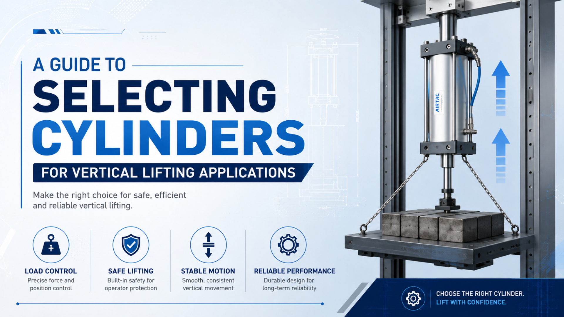
Select a cylinder for vertical lifting by calculating the worst-case upward force, checking which chamber performs the lift, sizing from the minimum pressure available at the cylinder, and separating motion control from load holding. A cylinder that can raise the mass under normal conditions isn’t automatically safe after an air-line break, valve fault, or power loss.
The basic lift-force estimate is F = m(g + a) + Ff, where m is the total moving mass, g is gravitational acceleration, a is the required upward acceleration, and Ff represents friction or other measured resistance. That demand must then be compared with usable cylinder force, mounting capacity, guide capacity, cushioning, and the machine’s risk-reduction measures.
Key Takeaways
- Calculate vertical demand from total moving mass and acceleration, then size from the lowest pressure expected at the actuator.
- Confirm whether the bore side or annular rod side lifts the load because retract force is lower.
- Treat speed control, load holding, guarding, and maintenance isolation as separate engineering functions.
- For one SMC lock-cylinder family, constant drop-prevention load is limited to 50% of rated holding force, showing why model-specific data matters.
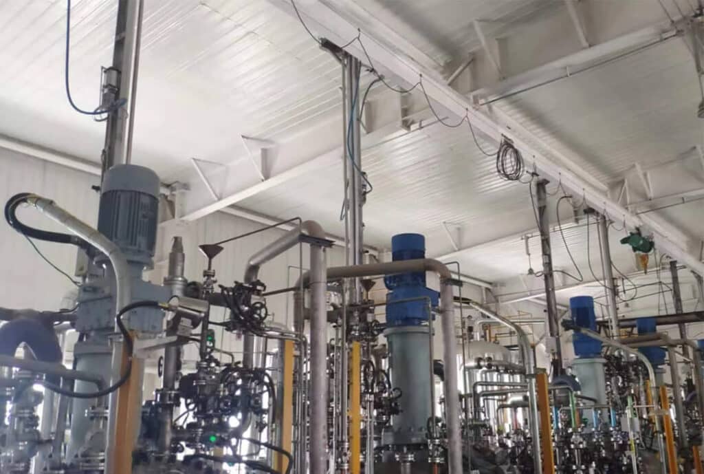
A vertical process mechanism needs a defined load path, external guidance where required, and a safe state for loss of air or electrical power.
What must be defined before selecting a vertical lifting cylinder?
ISO 4414:2010 remains current after its 2021 review and covers general rules and safety requirements for pneumatic systems (ISO, accessed 2026). Start the selection with the complete machine duty, not a bore-size guess: moving mass, direction, stroke, cycle time, pressure, mounting, access, and the required response to each foreseeable fault.
Record the payload together with every part that moves vertically. That can include a carriage, fixture, tooling, gripper, hose carrier, moving guard, coupling, and a portion of the guide assembly. Use the heaviest permitted product and the most demanding operating recipe, not the nominal part weight.
Then define the motion profile. How quickly must the load accelerate, travel, decelerate, and settle? A 100 kg assembly has a static gravitational force of about 981 N, but an upward acceleration of 1 m/s² adds another 100 N before friction and design margin. The acceleration requirement is often more useful than an arbitrary percentage added to the load.
The following inputs belong on the selection sheet:
| Input | Why it changes the selection |
|---|---|
| Total moving mass | Establishes gravitational and inertial force |
| Lift direction | Determines whether bore area or annular area produces lift |
| Minimum point-of-use pressure | Sets the usable cylinder force during the worst normal condition |
| Stroke and unsupported rod length | Affects package size, alignment, and buckling risk |
| Target speed and acceleration | Drives flow, valve, tubing, and cushioning requirements |
| External moments and side load | Determines whether a guided slide is required |
| Air-loss and power-loss state | Defines the need for a brake, lock, support, or controlled lowering method |
| Personnel access | Changes guarding, control-system, and maintenance requirements |
The useful design boundary is broader than “which cylinder lifts the weight?” The real question is whether the actuator, guides, controls, holding device, structure, and recovery procedure can manage the same mass through normal motion, stopping, fault response, and servicing.
How do you calculate the force required to lift the load?
Newton’s second law gives the upward actuator demand as F = m(g + a) before friction; using 9.81 m/s² for g, a 100 kg mass accelerating upward at 1 m/s² requires 1,081 N (NIST, accessed 2026). Add measured guide friction, seal resistance, external process force, and an application-specific margin rather than assuming one universal safety factor.
For a simplified first pass:
Required lift force = m(g + a) + friction + external process forceSuppose the moving mass is 120 kg, upward acceleration is 0.8 m/s², and measured guide plus process resistance is 150 N:
F = 120 x (9.81 + 0.8) + 150
F = 1,423 N
That is the mechanical demand during the specified acceleration, not the final catalog force. The chosen cylinder must produce enough usable force at the minimum pressure after accounting for its effective area and realistic losses. If the application can jam, collect material, ice up, or experience changing tool forces, quantify those cases separately.
Don’t hide uncertainty inside an oversized percentage. If the mass varies, state its maximum. If acceleration is unknown, obtain the motion profile. If friction hasn’t been measured, use a documented conservative estimate and validate it during commissioning.
Which cylinder area and pressure should be used for sizing?
A double-acting cylinder’s extension force uses the full bore area, while retract force uses the smaller annular area after subtracting rod area; a 63 mm bore with a 20 mm rod has about 10% less theoretical area on retraction. The exact relationship is explained in the site’s rod-area calculation guide.
Use these ideal-force equations:
Extension force = pressure x (pi x bore² / 4)
Retraction force = pressure x [pi x (bore² - rod²) / 4]
If retraction raises the load, size from the annular area. This detail can change the selected bore, especially when the rod is large or the point-of-use pressure is low. It can also change fault behavior because gravity assists extension while the controlled lift occurs on retraction.
Pressure deserves the same care. Measure or calculate the lowest pressure available at the cylinder during peak plant demand, with the valve shifting and other consumers running. Regulator set pressure isn’t proof of pressure at the actuator. Tubing, fittings, valve flow capacity, exhaust restriction, and shared supply lines all contribute to the difference. See the related guide to air-cylinder working pressure for a fuller pressure review.
Size force and flow as two linked checks. A large bore may meet force demand at low pressure, yet its larger chamber volume can require a bigger valve and tube to meet the same stroke time. Recalculate cycle flow after changing the bore.
How should stroke, mounting, guidance, and rod buckling be checked?
SMC’s current lock-cylinder literature separates maximum static holding force from permitted vertical load and lists orientation-specific limits, so catalog force alone cannot validate the installation (SMC Fine Lock Cylinders, accessed 2026). Check the complete mechanical load path: rod, bearing, mount, bracket, fasteners, carriage, guides, frame, and stops.
A standard cylinder is intended primarily to generate axial force. It shouldn’t be used as the sole linear guide when the lifted assembly creates substantial side load or overturning moment. Use external linear guides or a guided actuator so the guide system carries moments and preserves cylinder alignment. Misalignment increases seal and bearing wear and can make low-speed motion inconsistent.
Compression loading also introduces rod-buckling risk. The critical case depends on rod diameter, unsupported length, end conditions, material, and applied compression force. A longer stroke can reduce allowable compression load sharply, so verify the manufacturer’s buckling chart or use an engineering calculation before approving a long vertical push arrangement.
Mounting choice changes alignment and load transfer:
- Flange mounts suit a rigid, well-aligned axial load path.
- Foot mounts need a stiff base and careful alignment to avoid bending.
- Clevis and trunnion mounts allow pivoting where the mechanism follows an arc.
- Guided slides are preferable when the load introduces moments or needs high lateral stiffness.
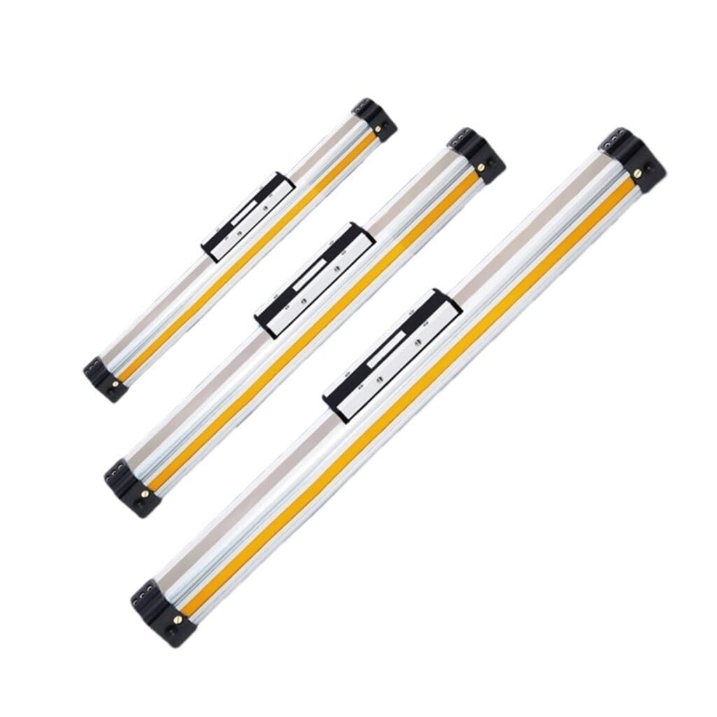
A rodless cylinder can shorten the installation envelope, but vertical use still requires verified carriage loads, moments, guidance, holding strategy, and fault behavior from the selected model’s documentation.
Which cylinder configuration fits the vertical axis?
SMC’s CLK2 lock-cylinder specifications list 40, 50, and 63 mm bores, spring locking, one-direction locking options, and 50 to 500 mm/s piston speed for that specific series (SMC CLK2, accessed 2026). Those limits illustrate why the configuration must be chosen from its documented load, direction, speed, and lock behavior.
For most controlled vertical axes, a double-acting cylinder is the starting point because pressure can drive both directions. It doesn’t become load-holding equipment merely because both ports are connected to a valve. Internal leakage, external leakage, pressure decay, or a shifted valve can still allow motion.
A single-acting cylinder may suit a task where the defined safe motion matches its spring or gravity return, but the phrase “spring return” doesn’t prove a safe state. Check the available spring force across the full stroke, the mass direction, exhaust path, failure position, and whether a person can enter the travel zone. The site’s single-acting versus double-acting guide covers the underlying actuator differences.
Use this decision table as a screening tool:
| Requirement | Configuration to evaluate | Verification still required |
|---|---|---|
| Guided compact lift | Guided cylinder or pneumatic slide | Moment capacity, guide life, holding method |
| Long stroke with limited envelope | Rodless cylinder | Carriage moments, vertical rating, seal behavior, brake/support |
| High axial force with simple motion | Double-acting rod cylinder | Buckling, mount stiffness, guide alignment |
| Load must remain raised after air loss | Cylinder plus rated mechanical holding device | Capacity, direction, engagement state, feedback, proof test |
| Load must stop while moving | Purpose-rated brake or stopping system | Kinetic energy, stopping distance, cycle rate, wear |
The cylinder family is only one layer. A compact rodless layout may save space, while a guided slide may simplify moment control. The safer choice is the configuration whose load ratings and failure behavior match the machine, not the one with the largest theoretical thrust.
How do you control vertical speed and end-of-stroke energy?
The SMC CLK2 series publishes a 50 to 500 mm/s piston-speed range, but that range belongs to one product family rather than all vertical cylinders (SMC CLK2, accessed 2026). Set the target speed from the process, then verify cylinder, valve, tubing, cushioning, brake, and guide limits for the actual moving mass.
Meter-out flow control is commonly used to create exhaust backpressure and stabilize pneumatic-cylinder speed. Vertical axes need extra care because gravity can drive one direction. A flow control can regulate normal descent, but it isn’t a positive load-holding device and shouldn’t be credited as one after a tube or fitting fails. The meter-in versus meter-out guide explains the circuit distinction.
End-of-stroke energy comes from the moving mass and velocity. Cushioning must absorb that energy within the cylinder’s published limit, or the design needs an external shock absorber, lower speed, longer deceleration, or a different actuator. Start commissioning at low speed, then tune each direction independently while monitoring pressure and impact.
Ask a practical question: if the load overshoots because exhaust flow changes, where does the energy go? The answer should point to a rated cushion, stop, or shock absorber, not to the end cap as an accidental brake.
What prevents the load from falling after air or power is lost?
For SMC’s CL1 large-bore lock-up family, a constant stationary load used for drop prevention must be no more than one-half of rated holding force, and locked speed is limited to 200 mm/s (SMC Fine Lock Cylinders, accessed 2026). Other products use different limits. Always follow the exact device’s orientation, direction, static-load, kinetic-energy, and release-pressure data.
Separate four functions that are often confused:
- Motion control commands extension, retraction, speed, and stopping during normal production.
- Load holding physically restrains a stopped load when pressure or power is lost.
- Emergency stopping arrests a moving load within a validated distance and energy limit.
- Maintenance support and isolation prevents hazardous movement while people service the machine.
A pilot-operated check valve may trap pressure near a cylinder port and reduce drift in an intact circuit. It doesn’t automatically protect against every downstream leak, seal bypass, structural failure, or maintenance intervention. A rod lock clamps the rod, but many locks are intended to hold a stopped load rather than brake a moving one. Read the dedicated cylinder rod-lock guide before specifying one.
For personnel-accessible hazards, use a machine risk assessment to define the safety function and required performance. ISO 13849-1:2023 provides a methodology for safety-related control-system parts, including pneumatic and mechanical technologies, but it doesn’t prescribe one performance level for every vertical lift (ISO, accessed 2026).
The most defensible architecture doesn’t ask trapped air to perform every job. It assigns normal motion to the pneumatic circuit, gravity restraint to a rated mechanical method, access prevention to guarding and safety controls, and maintenance protection to energy isolation plus blocking or restraint.
How should the vertical lifting system be commissioned and maintained?
OSHA 29 CFR 1910.147 requires hazardous energy control during servicing when unexpected energization, startup, or stored-energy release could harm employees, and its scope includes pneumatic energy (OSHA, accessed 2026). A control valve, emergency stop, or software command isn’t automatically an energy-isolating device.
Commission the vertical axis against documented acceptance criteria:
- Weigh or otherwise verify the maximum moving mass.
- Record minimum pressure at the cylinder during the worst production demand.
- Confirm full-stroke clearance, alignment, guide motion, and mount fastener torque.
- Measure lift and descent times at the approved load.
- Verify deceleration and end-of-stroke impact in both directions.
- Simulate defined air-loss, electrical-loss, sensor-fault, and emergency-stop cases safely.
- Confirm the load-holding device engages, holds, reports its state, and releases only under permitted conditions.
- Measure stopping distance when a brake is required to stop motion.
- Test restart and recovery so pressure restoration cannot cause an unexpected jump.
- Document the results, settings, load, pressure, software revision, and test date.
OSHA’s lockout guidance also requires stored or residual energy to be relieved, disconnected, restrained, or otherwise rendered safe during covered servicing (OSHA enforcement guidance, accessed 2026). A raised load may need a rated mechanical block or support even after air is exhausted. Maintenance intervals should come from the component manuals, risk assessment, duty cycle, environment, and proof-test strategy, not a generic monthly or six-month rule.
FAQs About Selecting Cylinders for Vertical Lifting Applications
ISO 4414 and ISO 13849-1 address different layers: pneumatic-system safety requirements and safety-related control-system design methodology, respectively (ISO 4414; ISO 13849-1, accessed 2026). These answers keep cylinder sizing, load holding, and personnel protection distinct.
Can a standard pneumatic cylinder be mounted vertically?
Yes, if its force, stroke, buckling, mounting, alignment, cushioning, and environmental ratings suit the application. Vertical orientation adds gravity-driven motion and a falling-load hazard. The complete design may therefore need external guides, a rated lock or brake, guarding, safety-related controls, and a mechanical maintenance support.
What safety factor should be used for a vertical pneumatic cylinder?
There is no single universal factor for every vertical axis. Calculate maximum force from mass, acceleration, friction, process loads, and minimum pressure, then apply the margin required by the risk assessment, company standard, and component manufacturer. Load-holding devices may have separate orientation-specific derating that must be followed.
Is a closed-center valve enough to hold a vertical load?
Not by itself when unintended movement creates an unacceptable risk. A closed-center valve can trap air, but leakage, seal bypass, pressure changes, tube failure, or maintenance work can defeat that condition. Use a separately rated holding or supporting method when the risk assessment requires positive restraint.
Should a vertical cylinder lift on extension or retraction?
Either arrangement can work, but the force and failure behavior differ. Extension uses the full bore area; retraction uses the smaller annular area. The mount, rod-buckling case, contamination exposure, available space, safe failure direction, and access to the load should decide the orientation.
How is a vertical cylinder tested after installation?
Test it at the approved maximum load and minimum operating pressure. Record speed, acceleration, stopping, cushioning, alignment, pressure, air-loss behavior, power-loss behavior, holding-device engagement, feedback, restart, and recovery. Perform fault simulations under controlled conditions with the hazard zone secured and the load independently supported where necessary.
Final selection checklist
SMC’s published lock-cylinder data shows that permitted vertical load, holding force, direction, and speed can all be separate ratings (SMC, accessed 2026). Before issuing a purchase order, confirm the calculation and the entire safety architecture in writing.
- Maximum moving mass and process force
- Required stroke, speed, acceleration, and cycle rate
- Lift direction and effective piston area
- Minimum measured or calculated pressure at the cylinder
- Selected bore, rod diameter, and theoretical forces in both directions
- Rod buckling, guide load, moment, mount, and frame checks
- Valve, tube, exhaust, and flow-control sizing
- Cushion or external energy-absorption capacity
- Defined state after air loss, power loss, tube failure, and emergency stop
- Holding or braking device ratings, direction, feedback, and proof test
- Guarding, access control, energy isolation, and maintenance support
- Environmental limits, inspection criteria, and documented commissioning results
The cylinder is ready for selection only when these answers agree. If the force calculation says yes but the load has no defined restraint after pressure loss, the vertical axis is still incomplete.
Sources
- ISO, “ISO 4414:2010 Pneumatic fluid power, General rules and safety requirements for systems and their components.” https://www.iso.org/standard/44790.html
- ISO, “ISO 13849-1:2023 Safety of machinery, Safety-related parts of control systems.” https://www.iso.org/standard/73481.html
- OSHA, “29 CFR 1910.147, The control of hazardous energy (lockout/tagout).” https://www.osha.gov/laws-regs/regulations/standardnumber/1910/1910.147
- OSHA, “29 CFR 1910.147 Inspection Procedures and Interpretive Guidance.” https://www.osha.gov/enforcement/directives/std-01-05-019
- SMC, “Fine Lock Cylinders, CL/CDL Series.” https://www.smcworld.com/catalog/en/actuator/CL_-CDL_-E/7-5-2-p0963-CL_1019-CL1_en/data/7-5-2-p0963-CL_1019-CL1_en.pdf
- SMC, “Clamp Cylinder with Lock, CLK2G/CLK2P Series.” https://ca01.smcworld.com/catalog/en/actuator/CLK2-E/7-5-2-p0461-0490-CLK2_en/data/7-5-2-p0461-0490-CLK2_en.pdf
- NIST, “Fundamental Physical Constants.” https://physics.nist.gov/cuu/Constants/