

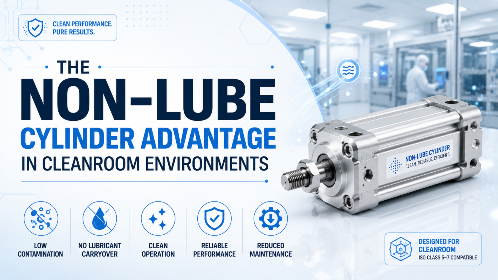
A non-lube cylinder is an actuator that can operate without oil added to its compressed-air supply. It can reduce one avoidable contamination route in a cleanroom. That is a real advantage, but it is not proof of zero emissions, grease-free construction, or automatic compliance with a particular ISO cleanroom class.
Selection is broader than the label: does the exact cylinder, installed in the intended position and run at the intended speed, load, pressure, and cycle rate, stay within the facility’s particle and chemical contamination limits? Reliable answers come from model-specific data and application qualification, not from the words “non-lube” alone.
Key Takeaways
- FDA guidance sets 3,520 particles/m³ at 0.5 µm and larger as the ISO 5 limit near exposed aseptic work.
- Non-lube isn’t grease-free.
- ISO 14644-14:2026 assesses equipment particle suitability under defined test conditions.
- Specify the whole operating envelope: materials, air quality, exhaust, cleaning, speed, load, cycles, sampling, and maintenance.
Strong cleanroom specifications separate three questions that are often mixed together: what is inside the cylinder, what the cylinder releases during motion, and what the installed machine does to the clean zone. Supplier datasheets may answer the first two. Only qualification in representative conditions can answer the third.
In our experience, this three-part distinction catches vague supplier claims before they enter a validation protocol. It also gives engineering and quality teams a shared vocabulary for reviewing grease, particle release, exhaust, and installed performance. That early check is cheap.
For related system context, see the guides to ISO compressed-air quality standards and pneumatic cylinder maintenance requirements.
Use the standards and manufacturer documents below to separate cleanroom compatibility, non-lube construction, particle behavior, and installed-machine qualification.
What Does a Non-Lube Cylinder Actually Mean?
Non-lube means the cylinder doesn’t need oil added to its operating air; it doesn’t mean the mechanism is dry. One SMC manual states that its non-lube cylinders are lubricated for life at the factory and specifies upstream filtration of 5 µm or smaller (SMC CG3 air-cylinder manual, accessed 2026).
Manufacturers often apply grease inside non-lube cylinders during assembly. They then select seals, bushings, surface finishes, and materials for operation without an airline lubricator. The correct language is usually “no additional lubrication required,” not “contains no lubricant.” If oil isn’t added to the air, factory-applied lubrication still handles the internal sliding interfaces. The mechanism still depends on lubricant.
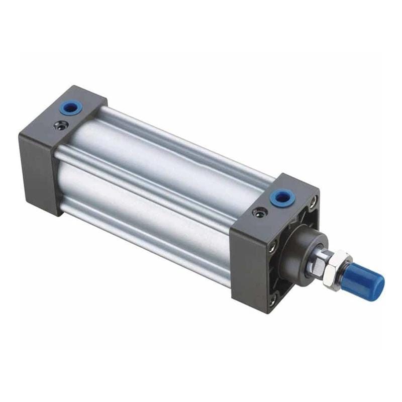
The SCSU Series tie-rod cylinder illustrates a standard non-lube format; product appearance alone does not establish cleanroom suitability.
This distinction changes procurement. Confirm whether the model is factory-lubricated, then record the grease type and allowed quantity. Ask separately whether added oil invalidates the low-particle specification. Material restrictions must fit the process. A semiconductor tool may care about airborne molecular contamination; a sterile filling line also has microbiological and cleaning requirements. Vacuum questions come next. Is suction required? Record the tested flow and line length. Document cleaning, packaging, orientation, speed, and load as separate fields. If any variable falls outside the test boundary, label it as a qualification gap instead of extending the claim. Apply the same rule after a seal replacement or grease change because service can alter emissions.
| Label or claim | What it can establish | What it cannot establish |
|---|---|---|
| Non-lube | No airline oil is required under stated conditions | Zero internal grease or zero particles |
| Food-grade grease | Lubricant formulation may fit a stated food-contact policy | Cleanroom particle class |
| Cleanroom-tested | The tested sample met a documented method and condition | Every mounting position, speed, load, and life stage |
| ISO class statement | A result tied to a particle size and test condition | Chemical, viable, or surface cleanliness unless separately tested |
The Cleanroom Advantage, in Practical Terms
For aseptic processing, FDA guidance associates ISO 5 with no more than 3,520 particles of 0.5 µm and larger per cubic meter near exposed sterile work (FDA Aseptic Processing Guidance, 2004). A suitable non-lube cylinder can protect that particle budget by removing the need for an oil-mist lubricator.
The benefit is narrower and more defensible than “zero contamination.” Eliminating an airline lubricator avoids deliberately introducing an oil aerosol upstream of the valve and cylinder. It also removes a lubrication setting that can drift and a maintenance step that can introduce the wrong oil. Those gains matter most when exhaust or moving surfaces are close to exposed product.
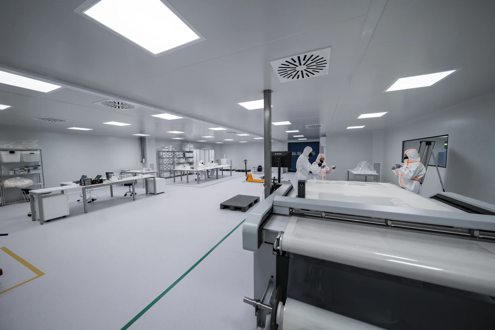
Cleanroom equipment must be assessed with people, airflow, tools, and production motion present. Photo by TECNIC Bioprocess Solutions on Unsplash. Motion changes the measurement.
Non-lube construction also simplifies the contamination-control plan. There is no lubricator bowl to refill, no oil-feed rate to verify, and no deliberate oil mist to route through the exhaust. But the cylinder still has seals, grease, wear surfaces, tubing, fittings, a valve, and an exhaust path. Why does that matter? Each can release particles, condensate, chemicals, or process residue. The European Commission’s 2022 sterile-manufacturing guidance requires a facility-wide contamination control strategy and lists equipment, utilities, preventive maintenance, cleaning, monitoring, and vendor approval among its control elements (EU GMP Annex 1, 2022). A non-lube cylinder belongs inside that strategy. It doesn’t replace it. The practical advantage is one fewer intentional oil source within a larger, documented control system.
Does Non-Lube Mean ISO 14644 Compliant?
Non-lube alone does not establish cleanroom compliance for a specific component or installation. ISO 14644-1 classifies airborne particle concentrations from 0.1 to 5 µm. ISO 14644-14:2026 provides the equipment-suitability method for components and tools (ISO 14644-1, 2015; ISO 14644-14, 2026).
ISO 14644-1 classifies the air in a cleanroom, clean zone, or separative device. It does not certify a cylinder by product category. ISO 14644-14 addresses equipment suitability by airborne particle concentration, which is the more relevant framework when a buyer wants evidence for a moving component. Cleanroom suitability means that a defined component or material meets a stated cleanliness requirement under documented conditions. The statement is only useful when it identifies the standard, particle or chemical threshold, operating state, sampling location, and test configuration. Context is the specification. Chemical contamination needs another boundary. ISO 14644-15:2026 covers equipment and material suitability by airborne chemical concentration, and its scope is linked to ISO 14644-8 (ISO 14644-15, 2026). Neither Part 14 nor Part 15 covers biocontamination, cleanability, or compatibility with cleaning agents. Those questions need separate evidence.
Treat “ISO compliant” as an incomplete sentence. Complete it with the standard part, class or concentration limit, particle or chemical species, test state, sampling position, and operating envelope. Would you accept a motor as cleanroom compliant only because it has sealed bearings? A cylinder deserves the same engineering discipline.
Use this evidence hierarchy:
- A model-specific report that names the sample, counter, particle threshold, sampling geometry, motion profile, background concentration, uncertainty, and measured result.
- A manufacturer catalog that identifies the tested model and operating limits.
- A component-family statement with clear conditions, configuration boundaries, and exclusions that can be checked against the quoted part number.
- A generic label. Treat it as screening only.
Which Cylinder Features Actually Control Particle Release?
Cleanroom performance comes from the complete design and operating envelope, not a lubrication label. In one documented SMC CYP test, particle generation was reported at one-twentieth of a previous model through 500,000 cycles at 200 mm/s with a 5 kg load, but the catalog says the data are not guaranteed (SMC CYP catalog, accessed 2026).
That example is useful because it includes the conditions. The design used non-contact construction between the cylinder tube exterior and slide table, a specially treated stainless-steel guide, and a defined test cylinder, stroke, load, and speed. Change those variables and the result may change. What should a buyer ask instead of accepting “low particle generation” at face value?
| Feature to verify | Why it matters in a cleanroom | Evidence to request |
|---|---|---|
| Factory grease | Can affect particles, vapour, outgassing, and process chemistry | Grease type, restrictions, quantity control, safety data |
| Rod seal and wiper | Sliding contact can generate particles or carry residue | Material, geometry, replacement limit, test report |
| Guide and bearing design | Side load and contact can increase wear | Allowable load and moment, mounting rule, life-test condition |
| Vacuum or relief port | Can capture particles or route leakage away | Required suction flow, pressure, tubing limit, monitoring point |
| Exhaust arrangement | Valve exhaust can disturb local airflow or release contaminants | Port map, silencer material, remote-exhaust method |
| Surface and fasteners | Affect shedding, cleanability, corrosion, and residue traps | Materials list, finish, exposed-thread and recess review |
| Packaging and assembly | Controls contamination introduced before installation | Clean assembly status, double-bag method, opening procedure |
Don’t assume PTFE seals, stainless steel, or a vacuum port are universal. Those are model-level features. Confirm them against the exact bore, stroke, option code, and production revision in the quotation.
For seal selection outside the cleanroom claim, review the exact material and geometry against the manufacturer manual. For electronics assembly context, see compact cylinders in automated PCB lines. Generic material labels aren’t enough.
How Should You Qualify a Cylinder for Cleanroom Use?
A defensible qualification reproduces the real installation and operating state. FDA guidance recommends monitoring ISO 5 filling areas during every production shift and sampling where exposed product has the highest risk; it also calls for documented evaluation of equipment design under dynamic conditions (FDA Aseptic Processing Guidance, 2004).
Start with a written acceptance criterion. Name the cleanroom class or process limit, particle size, measurement location, room state, background level, cycle count, operating speed, pressure, load, orientation, and whether vacuum extraction is active. Without those items, a particle count can’t be reproduced or compared. Equipment qualification is the documented demonstration that the installed cylinder performs within those criteria. It should connect the component test to the actual machine layout, airflow, product exposure, maintenance state, and worst credible operating condition. Installation details decide the result. The protocol should also state how background counts will be subtracted, how an excursion will be investigated, and which maintenance or configuration change triggers requalification.
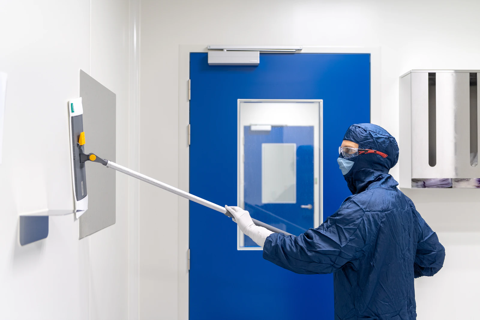
Qualification should test the installed equipment in its relevant operating state. Photo by Toon Lambrechts on Unsplash.
A practical test sequence is:
- Record the exact cylinder, option code, serial or batch identity, grease, packaging state, valve, tubing, mounting drawing, and nearby product exposure.
- Measure the clean zone at rest and establish background particle concentration.
- Run minimum, normal, and worst-case conditions, including startup, maximum speed, rated load and moment, pressure extremes, cycle bursts, and active or inactive vacuum suction.
- Sample at the likely release path, product exposure point, guide, seal, exhaust, and vacuum outlet using documented probe positions.
- Repeat after run-in and near the planned maintenance limit.
- Record raw counts, background correction, deviations, cleaning, seal or grease changes, counter calibration, and every configuration that would invalidate or limit the conclusion.
The EU GMP Annex 1 guidance gives 10 Pa as a minimum guidance value between adjacent rooms of different grades and requires airflow studies both at rest and in operation (EU GMP Annex 1, 2022). That reinforces a key point: a cylinder test must consider its effect on local airflow, not just particles inside a small chamber.
From our work on application reviews, we treat the supplier test as screening evidence and the installed-machine test as acceptance evidence. The distinction saves arguments later. A component can perform well in a chamber yet create a problem when its exhaust points across exposed product or when a side-loaded guide wears faster than the catalog test condition.
How Should You Control Compressed Air, Exhaust, and Installation?
Compressed air must be specified separately from room air. ISO 8573-1 defines purity classes for three principal contaminant groups: particles, water, and oil. It also identifies gaseous and microbiological contamination (ISO 8573-1, 2010). That makes the air supply, valve exhaust, tubing, and silencers part of the cleanroom risk review.
Removing the lubricator is only one step. Specify the point-of-use particle, water, and oil limits; confirm the compressor and treatment train can meet them; and decide where the exhaust goes. A valve exhausting beside exposed product may create a local airflow and contamination problem even when the cylinder itself has low particle generation.
Check these installation controls:
- Use filtered, dry air within the cylinder manufacturer’s limits. Extremely dry air can also affect some internal lubrication systems, so don’t specify a dew point without checking the model manual.
- Remove or bypass oil-mist lubricators only after confirming every downstream valve and actuator is approved for non-lubricated service.
- Route exhaust outside the critical zone or through a validated filter when the process risk assessment requires it.
- Use tubing, fittings, silencers, thread sealants, and valve grease that meet the same material restrictions as the cylinder.
- Keep speed controls and cushions within the tested range. Impact and side load can create wear particles.
- Open clean packaging at the controlled transfer point, then clean and disinfect the assembly using an approved method.
The compressed-air specification should be written at the point of use, not only at the compressor room. For filtration context, review how coalescing filters control oil aerosol and confirm that the selected FRL components meet the same air-quality boundary.
What Changes in Maintenance and Total Cost?
Non-lube can remove one maintenance task, but it doesn’t remove maintenance. SMC’s clean-series guidance caps cylinder speed at 400 mm/s when retaining its stated particle-generation grade and warns that unapproved grease can cause particle generation (SMC Clean Series Precautions, accessed 2026). Treat speed, grease, seals, and cleaning as controlled parameters.
The maintenance plan should cover seal and guide wear, mounting alignment, tubing damage, leakage, exhaust filters, vacuum suction, sensors, cleaning compatibility, and packaging for replacement parts. Don’t add grease during a routine service unless the exact manual calls for it. A well-intended lubricant change can invalidate the particle performance or damage the original grease system. For total cost, replace universal payback claims with site data. The U.S. Department of Energy reports that compressed-air leaks can waste 20% to 30% of compressor output (DOE Energy Tips, 2000). That is a system-level reason to measure leakage, but it doesn’t prove a cleanroom cylinder will save a fixed amount. Include qualification labour, clean packaging, vacuum energy, monitoring, cleaning, spare parts, and the cost of repeating tests after a controlled change.
Use this worksheet:
Annual ownership cost = purchase and qualification + planned maintenance + compressed-air and vacuum energy + cleaning and monitoring + expected downtime and replacement riskCompare the current and proposed designs with the same production hours, air pressure, cycle rate, labour rate, test frequency, and failure assumptions. Does the non-lube option remove an oil-feed task? Good. Does it require vacuum suction, special grease, clean packaging, or more frequent particle verification? Count those costs too.
What Should Be on a Cleanroom Cylinder RFQ?
A useful RFQ asks for evidence, not the phrase “cleanroom ready.” ISO 14644-14:2026 is a 20-page equipment-suitability standard covering particle sizes from 0.1 µm to 5 µm and above; the supplier should state the tested model, particle threshold, operating conditions, sampling setup, and result (ISO 14644-14, 2026).
Festo’s cleanroom guidance makes the same application point: suitability depends on installation position and operating parameters, with an example that distinguishes ISO 4 above a workpiece from ISO 7 below it (Festo cleanroom guidance, accessed 2026). Send the actual layout instead of requesting a class number in isolation.
| RFQ item | What to provide | What to request back |
|---|---|---|
| Cleanliness target | ISO class, particle size, chemical or viable limits | Applicable standard part and declared result |
| Installation | Drawing, orientation, distance to exposed product | Tested mounting position and release direction |
| Motion | Bore, stroke, speed, acceleration, cycles, load, moment | Tested operating envelope and derating rules |
| Pneumatic supply | Pressure, point-of-use ISO 8573 class, dew point | Air-quality limits and lubrication prohibition |
| Exhaust and suction | Valve location, remote exhaust, vacuum availability | Port layout, suction flow, filter requirements |
| Materials | Restricted substances, cleaning agents, temperature | Material list, grease type, compatibility statement |
| Qualification | Sampling location, room state, acceptance limit | Test method, report, sample count, uncertainty or caveat |
| Maintenance | Planned service interval and access constraints | Seal kit, grease rule, cleaning method, replacement trigger |
| Delivery | Transfer route and packaging procedure | Assembly environment, bagging, opening instructions |
If no model-specific report exists, ask whether the supplier can test the quoted configuration. A transparent “not tested” answer is more useful than a broad compliance statement. It tells the qualification team exactly what still needs to be proven. Uncertainty is visible.
Our team found that supplier replies become easier to compare when every RFQ asks for the same test fields. The goal isn’t to force a universal certificate. It is to expose which limits are documented, which are inferred, and which still require installed qualification.
Conclusion: Treat Non-Lube as a Starting Point
Two ISO equipment standards were revised in 2026: Part 14 addresses airborne particle cleanliness, and Part 15 addresses airborne chemical cleanliness (ISO 14644-14, 2026; ISO 14644-15, 2026). That split captures the main lesson: a non-lube cylinder is useful, but only application-specific evidence completes the cleanroom decision.
Choose non-lube construction to avoid adding oil to the operating air and to simplify one part of the maintenance system. Then verify the factory grease, materials, seals, guide design, exhaust, suction, packaging, cleaning compatibility, air quality, speed, load, and particle data for the exact model. Start with the boundary.
The defensible claim is not “zero contamination.” It is narrower: the specified cylinder, installed and maintained as documented, met a defined acceptance limit under representative conditions. That statement can survive an engineering review, a quality audit, and a supplier change.
FAQs About Non-Lube Cylinders in Cleanrooms
FAQ answers should preserve the measurement boundary. ISO 14644-1 considers threshold particle sizes from 0.1 to 5 µm. FDA’s ISO 5 example counts particles at 0.5 µm and larger (ISO 14644-1, 2015; FDA, 2004). A class number without particle size, operating state, and test location is incomplete.
Does a non-lube cylinder contain no grease?
Usually not. SMC states that one non-lube cylinder family is lubricated for life at the factory and needs no added oil during operation. Its clean-series products use factory-applied fluororesin grease. Read the exact model manual because grease type, quantity, material restrictions, and re-lubrication rules are product-specific (SMC CG3 manual, accessed 2026).
Does a non-lube cylinder automatically comply with ISO 14644?
No. ISO 14644-14:2026 provides a method for assessing equipment suitability across particle sizes from 0.1 µm to 5 µm and above. Ask for the tested model, mounting position, speed, load, cycle count, suction condition, particle threshold, sampling setup, and measured result. A generic non-lube label is not test evidence.
Which ISO cleanroom class can a non-lube cylinder be used in?
There is no universal class for all non-lube cylinders. Festo notes that suitability depends on installation position and operating parameters. Its example places an ISO 4 requirement above a workpiece and allows ISO 7 below it (Festo cleanroom guidance, accessed 2026).
Should a cleanroom pneumatic system use an airline lubricator?
Don’t add a lubricator unless every downstream component manual permits or requires it. One SMC manual specifies 5 µm upstream filtration and says its cylinders are factory-lubricated for life. Also define point-of-use compressed-air purity for particles, water, and oil under ISO 8573-1 rather than relying on “clean air” as a verbal requirement.
How should I calculate the payback from switching to non-lube cylinders?
Don’t assume a universal 6 to 12-month payback. Use purchase, qualification, maintenance, air and vacuum energy, monitoring, downtime, and contamination-risk data from the actual line. DOE’s 20% to 30% compressed-air leak range supports measuring system leakage, but it does not establish the savings from one cylinder (DOE Energy Tips, 2000).
Source Notes and Retrieval Dates
The 11 sources below define the article’s standards and evidence boundary. ISO published revised Part 14 in February 2026 and Part 15 in May 2026, so use those editions instead of the withdrawn 2016 and 2017 versions (ISO 14644-14, 2026; ISO 14644-15, 2026).
-
ISO 14644-1:2015: Classification of air cleanliness by particle concentration, scope, particle-size range, and classification method. Retrieved 2026-07-10.
-
ISO 14644-14:2026: Assessment of suitability for use of equipment by airborne particle concentration, equipment-suitability method and scope. Retrieved 2026-07-10.
-
ISO 14644-15:2026: Assessment of suitability for use of equipment and materials by airborne chemical concentration, chemical-airborne-cleanliness scope and exclusions. Retrieved 2026-07-10.
-
FDA: Sterile Drug Products Produced by Aseptic Processing, Current Good Manufacturing Practice, ISO 5 particle limit, dynamic qualification, and monitoring guidance. Retrieved 2026-07-10.
-
European Commission: EU GMP Annex 1, Manufacture of Sterile Medicinal Products, contamination control strategy, equipment, utilities, maintenance, airflow, and qualification. Retrieved 2026-07-10.
-
ISO 8573-1:2010: Compressed air contaminants and purity classes, particles, water, oil, and additional contaminant categories. Retrieved 2026-07-10.
-
SMC CG3 Air Cylinder Operation Manual, factory lubrication, 5 µm filtration, and air-quality cautions. Retrieved 2026-07-10.
-
SMC CYP Clean Rodless Cylinder Catalog, model-specific low-particle design, test conditions, limits, and caveats. Retrieved 2026-07-10.
-
SMC Clean Room Equipment Catalog, factory grease, speed limits, packaging, vacuum ports, and clean-series precautions. Retrieved 2026-07-10.
-
Festo: Cleanroom, application-dependent suitability, mounting position, and operating parameters. Retrieved 2026-07-10.
-
U.S. Department of Energy: Energy Tips, Minimize Compressed Air Leaks, system leakage range and leak-management method. Retrieved 2026-07-10.