

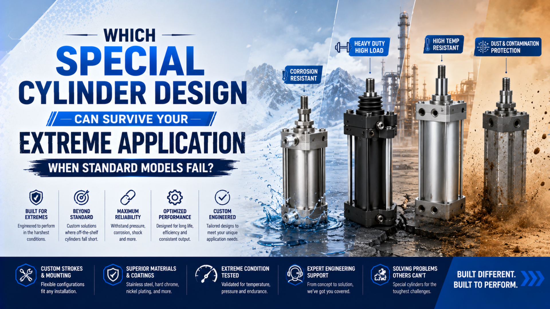
Special pneumatic cylinder design is the process of matching an actuator architecture to the mechanism that is causing a standard unit to fail. Heat needs a complete high-temperature configuration. Chemical splash needs verified material and seal compatibility. Side load needs guidance. Tight positioning needs feedback and control. A stronger-looking body cannot compensate for the wrong architecture.
This article is a selection guide, not a catalog of exotic materials. It shows how to identify the failure boundary, choose a documented special variant, and define acceptance evidence before committing to a custom cylinder.
Key Takeaways
- ISO 15552 covers interchangeable cylinders rated up to 1,000 kPa (10 bar), not every extreme environment.
- Select the architecture from the failure mechanism, then verify the complete model code.
- Magnetic coupling does not create positioning accuracy.
- Treat chemical, cleanroom, and safety claims as testable requirements.
Which Special Pneumatic Cylinder Design Matches the Failure Evidence?
ISO 15552 standardizes mounting and accessory dimensions for detachable-mount cylinders rated up to 1,000 kPa (10 bar), with bores from 32 to 320 mm (ISO, 2018). Those dimensions support interchangeability; they do not certify chemical resistance, cleanroom suitability, side-load capacity, low-temperature starts, or machine positioning accuracy.
A failed standard cylinder is not proof that the application needs an exotic alloy. First identify what failed and under which condition. A rod seal that hardens after cold starts points to a different solution than a rod that scores under lateral load. A carriage that misses position can be a control, guide, valve, load, or stopping problem rather than a cylinder-body problem.
Record the evidence before choosing a replacement:
- failed component and failure surface;
- time or cycles to failure, without converting an estimate into a life rating;
- minimum and maximum ambient, air, and component temperatures;
- working pressure at the cylinder ports, including transient lows and highs;
- speed, moving mass, orientation, duty cycle, and end-of-stroke behavior;
- side load and applied pitch, yaw, and roll moments;
- exact contaminant, concentration, exposure route, and cleaning method;
- required machine position tolerance and how it is measured;
- safe state after loss of air, electricity, control signal, or magnetic coupling.
The useful design question is not “Which cylinder is tougher?” It is “Which boundary was crossed?” That wording prevents a supplier from solving a seal problem with a larger bore, a guidance problem with higher pressure, or a control problem with a precision-sounding product label.
Special Pneumatic Cylinder Design: Catalog, Configured, or Custom?
SMC’s environment-resistant cylinder catalog separates stainless, hygienic, water-resistant, stable-lubrication, dust-resistant, heat-resistant, and cold-resistant products into distinct families or options (SMC, accessed 2026). Choose a catalog special first when its documented limits close the failure boundary; “special cylinder” is not one construction, material, or performance class.
Use the least-custom solution that closes the proven gap:
A catalog special is a published series or option with fixed limits. A configured standard is an approved combination of options on an existing platform. A true custom cylinder changes a pressure boundary, geometry, material, interface, guidance, sensing method, or validation requirement that no documented standard configuration can satisfy.
| Supply level | What changes | Best use | Evidence to request |
|---|---|---|---|
| Catalog special | A published series or option with fixed limits | One known condition such as cold, washdown, dust, compact envelope, or guided load | Current datasheet, exact model code, exclusions, derating, maintenance instructions |
| Configured standard | Approved combination of standard bore, stroke, mount, rod, seal, switch, cushion, and accessory options | Several compatible requirements within an existing platform | Configuration drawing, option compatibility, complete operating limits |
| True custom | Pressure boundary, geometry, materials, interfaces, guidance, sensing, or validation plan changes | No documented catalog configuration satisfies the risk | Controlled drawing, calculations, material certificates, inspection plan, prototype test |
A catalog special usually carries less engineering risk because the manufacturer has already defined its combinations and exclusions. A true custom cylinder can be justified, but it should begin with a requirements baseline and acceptance plan. Our separate guide to custom pneumatic cylinder design covers that build-to-spec process in detail.
In our experience reviewing applications, the expensive mistake is often premature customization. A nonstandard rod end or seal may be easy to build yet hard to maintain. If a published dust-resistant or low-temperature option meets the requirement, its model code, spare-parts path, and service instructions are usually more valuable than novelty.
Which Design Survives Chemicals, Corrosion, and Washdown?
ISO 9227 defines three salt-spray methods: NSS, AASS, and CASS. It also states that these tests are not intended to rank materials for corrosion resistance or predict long-term service (ISO, 2022). A salt-spray-hour claim therefore cannot replace application-specific chemical compatibility and exposure validation.
Begin with the exact exposure, not a broad label such as “acid resistant” or “stainless.” The same chemical can attack differently as concentration, temperature, oxygen content, deposits, stress, or wet-dry cycling changes. External splash is also different from compressed air that carries vapor through the cylinder.
Specify the complete exposure map
List every substance that can contact the actuator:
- process chemicals, cleaners, disinfectants, salt, steam, and rinse water;
- maximum concentration and temperature, including cleaning cycles;
- external splash, spray, immersion, vapor, or internal pneumatic exposure;
- duration, frequency, drainage, crevices, and areas where residue collects;
- contact between dissimilar metals and the presence of a conductive electrolyte.
Then evaluate the tube, end caps, rod, fasteners, bearings, ports, switches, cable jackets, seals, wiper, lubricant, and adhesive separately. A corrosion-resistant rod does not protect an unsealed switch groove. A chemically resistant seal may still wear rapidly if deposits dry on the rod.
Ask for evidence that matches the failure
Material certificates confirm alloy identity; they do not confirm application life. Coating thickness, adhesion, porosity, surface finish, passivation, and post-machining treatment may matter. For a critical application, define a representative exposure test, dimensional or surface inspection after testing, and a functional leak and motion test.
For stainless-steel washdown designs, drainage and cleanability can be as important as nominal alloy grade. See the focused guides to washdown cylinder selection and galvanic corrosion between cylinder components.
What Changes for Heat, Sub-Zero Starts, Dust, and Cleanrooms?
ISO 14644-14 assesses equipment suitability over airborne particle sizes from 0.1 µm to 5 µm and larger (ISO, 2026). The standard does not cover biocontamination, cleanability, material selection, or process performance. Calling a cylinder “ISO Class 6 certified” without a defined equipment test and operating condition is incomplete.
Temperature and contamination problems need different architectures, even when both are sold as environment-resistant.
Temperature is a complete-model limit
The lowest-rated part governs. A metal tube may tolerate a temperature that damages seals, grease, sensors, bumpers, cable insulation, or magnetic materials. Specify ambient temperature, compressed-air temperature, radiation, conduction through mounts, cycling heat, and the temperature after a shutdown soak.
Cold applications also need a pressure-dew-point strategy. Condensate that freezes in a port or cushion needle can stop motion even when the seal compound remains flexible. Verify the exact cylinder option at cold start, warm running, and repeated thermal cycling. Our sub-zero cylinder design guide explains this boundary in depth.
Dust control and cleanroom control are opposite flow problems
A dusty plant needs to prevent abrasive material from entering the rod and bearing interfaces. Scrapers, bellows, positive-pressure protection, protected guides, and serviceable sacrificial components can help, but each has speed and maintenance limits. Start with particle type, size, hardness, moisture, packing behavior, and the direction from which contamination arrives.
A cleanroom application needs to control what the actuator emits or transports. Friction particles, grease migration, exhaust, tubing, external slides, and maintenance activity all count. Assess the complete moving assembly in the intended orientation, speed, load, pressure, and duty cycle. Component marketing language cannot classify the room or the installed process.
Compact, Guided, and Rodless Design Trade-Offs
SMC’s CQ2 compact-cylinder family spans bore sizes from 4 to 200 mm and reports a 5% to 13% weight reduction for the current design versus its preceding CQ2 series (SMC catalog, accessed 2026). These are model-specific facts, not a universal force or life penalty for compact cylinders.
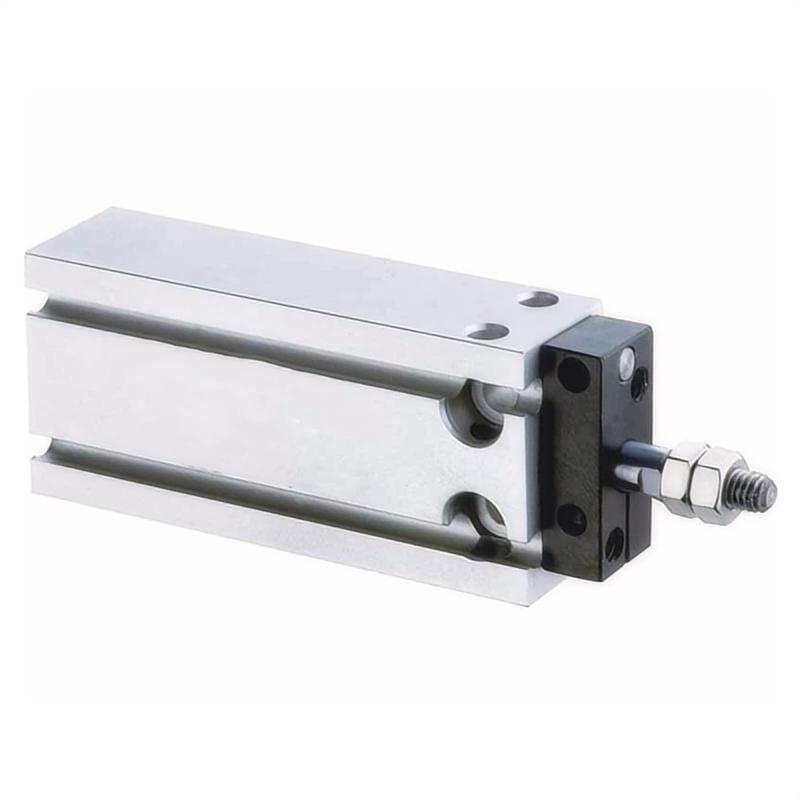
Compare the total installed envelope: cylinder, rod travel, fittings, tubing bend radius, switch connectors, adjustment access, load guide, shock absorber, and maintenance clearance. A short cylinder body can still produce a larger machine if it needs an external guide or inaccessible rear port.
For a conventional piston, theoretical extension force follows effective pressure and piston area. Net available force is lower because pressure at the port, seal friction, acceleration, and external resistance all matter:
Here, is usable axial force in newtons, is pressure at the working chamber in pascals, is effective piston area in square metres, and represents cylinder friction. The relationship does not impose an automatic percentage penalty merely because the body is compact.
Use a guided compact cylinder when the tooling applies moment or side load that the rod bearing cannot safely carry. Compare the manufacturer’s allowable load and moment curves at the actual stroke, mounting orientation, speed, and load-center offset. Don’t increase pressure to hide a guidance problem; that raises actuator force and stopping energy without removing the moment.
A rodless cylinder can reduce installed length when rod travel is the envelope problem. Mechanical-slot and magnetic-coupling designs have different sealing, contamination, load, and failure behavior. The rodless-versus-standard cylinder comparison covers their load paths and long-stroke limits.
Can a Magnetically Coupled Rodless Cylinder Deliver Precision Positioning?
SMC’s CY1S catalog lists seven bore sizes from 6 to 40 mm and states that an adjustment bolt improves stroke accuracy and repeatability (SMC, accessed 2026). The series data still requires load, pressure, stroke, orientation, and magnetic-decoupling checks. It does not promise universal machine-position accuracy.
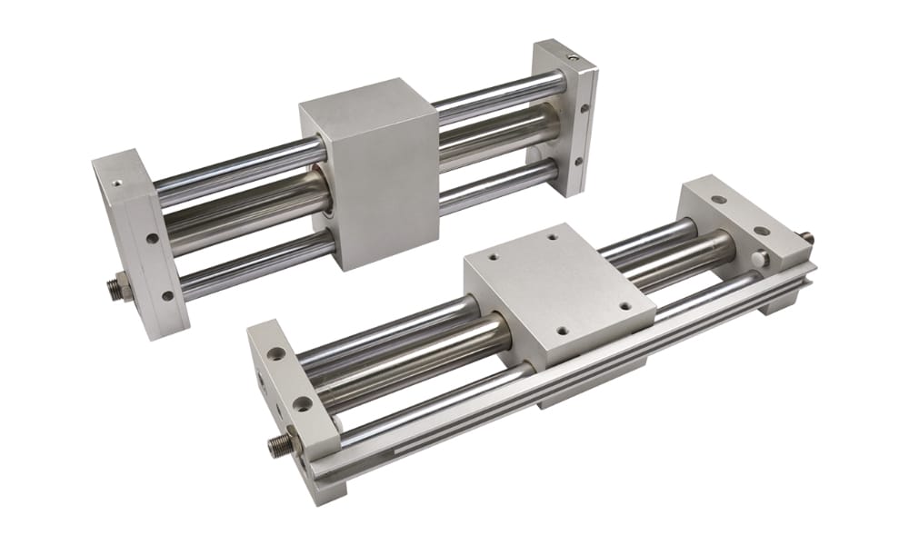
Magnetic coupling transfers force through the nonmagnetic tube wall. It does not measure the carriage coordinate. It can also separate if demand exceeds the allowed coupling force, pressure, acceleration, load, or stopping condition. After decoupling, the internal piston and external carriage may no longer share the assumed position.
Separate four specifications that are often mixed together:
- Stroke-end adjustment controls the nominal endpoint or stop.
- Cylinder-switch repeatability describes where a switch changes state under stated conditions.
- Carriage repeatability describes variation when the same move is repeated.
- Machine positioning accuracy compares the commanded and measured tool coordinate across the working range.
For a tight coordinate tolerance, define the external guide, position sensor, controller, valve, motion profile, mechanical datum, load variation, thermal range, and settling-time criterion. Measure the tooling coordinate, not only the piston magnet. A discrete end switch normally confirms a zone, not an exact position. The detailed internal-magnet and sensor guide explains that distinction.
Magnetic decoupling should be treated as a diagnosable machine state. If it can create a hazardous or damaging mismatch, add a way to detect carriage position independently, define recovery behavior, and prevent an automatic restart from assuming that piston and carriage remain synchronized.
Safety for High-Cycle, Impact-Loaded, and Vertical Axes
ISO 4414 applies to the design, construction, and modification of pneumatic systems and addresses significant hazards across intended use, adjustment, maintenance, cleaning, reliability, energy efficiency, and the environment (ISO, 2010). A cylinder’s published 10 bar dimensional standard does not replace the machine-level safety review required for the installed axis.
High cycle rate raises heat, seal travel, valve duty, air demand, and the number of stopping events. Impact energy depends on moving mass and velocity, not bore alone. Check the cylinder’s allowable kinetic energy or cushion data, and add an external shock absorber or controlled deceleration when the internal cushion cannot absorb the event with margin.
Vertical axes need a defined response to lost pressure and lost power. A check valve can delay motion, but leakage prevents it from being treated as an indefinite mechanical support. Depending on the risk assessment, the system may require a rod lock, mechanical catch, counterbalance, guarded exclusion zone, safe exhaust strategy, or another load-holding measure.
Also verify:
- maximum cycle rate and duty statement for the exact model;
- side load and moment through acceleration and stopping;
- cushion adjustment range at minimum and maximum payload;
- temperature after sustained production cycling;
- sensor and cable life at the actual flex pattern;
- safe isolation and release of stored pneumatic energy before service;
- behavior after an emergency stop and controlled restart.
When moving mass and speed are known, the Cylinder Cushion Energy Calculator can screen the stopping-energy case. Use the result to compare with manufacturer data; it is not a substitute for the final machine risk assessment.
Special Pneumatic Cylinder Design Evidence Required Before Approval
ISO 9227 identifies three controlled salt-spray procedures but explicitly rejects their use as a long-term life predictor (ISO, 2022). This is a useful purchasing rule: one result proves only what its method, specimen, duration, and acceptance criteria measured. A brochure adjective cannot close an engineering requirement.
Build an evidence matrix before releasing the purchase order:
| Requirement | Weak evidence | Approval evidence |
|---|---|---|
| Temperature | “Cold resistant” | Exact model range, changed materials, exclusions, cold-soak functional test |
| Chemical exposure | Alloy name or generic compatibility chart | Exact media, concentration, temperature, exposure route, component-level compatibility, representative test |
| Washdown | Stainless body | Complete external materials, ingress paths, drainage, cleaner compatibility, installed spray test |
| Dust | Extra wiper | Particle description, entry path, scraper/bellows limits, inspection interval, contamination test |
| Cleanroom | “Clean design” | Test method, operating state, particle sizes, orientation, load, speed, maintenance condition |
| Side load | Large rod diameter | Allowable load and moment curves at stroke and orientation, guide-life calculation |
| Precision | Adjustment screw or magnetic switch | External measurement method, error budget, repeatability test, settling criterion |
| Safety | Check valve | Loss-state analysis, load-holding method, isolation, restart behavior, validation record |
Avoid accepting a family-level datasheet when the quotation contains an unreviewed suffix. Special options can change pressure, temperature, speed, lubrication, cushioning, switch compatibility, or available strokes. Freeze the complete model code, drawing revision, and deviation list before testing.
Which RFQ and Acceptance Tests Keep the Selection Honest?
ISO 15552 was reviewed and confirmed in 2025 and remains current for its defined 10 bar, 32-to-320 mm interchangeable-cylinder scope (ISO, 2018). Use standards as boundary documents: cite the applicable requirement, then add every environmental, motion, control, and safety condition that the standard does not cover.
A useful RFQ separates requirements from preferences. “Must survive alkaline washdown at the stated concentration and temperature” is a requirement. “Prefer an aluminum profile” is a preference unless the machine interface makes it mandatory.
Include these inputs:
- Motion: bore or required force, stroke, orientation, speed profile, cycle rate, duty, moving mass, and stopping time.
- Load path: mounting, rod-end connection, side load, load-center offsets, pitch/yaw/roll moments, and external guide.
- Air: minimum dynamic port pressure, maximum regulated pressure, air temperature, filtration, lubrication policy, dew point, and exhaust arrangement.
- Environment: ambient range, exact chemicals, cleaning cycle, dust, moisture, radiation, cleanroom operating state, and hazardous-area classification where applicable.
- Control: valve type, sensing function, required coordinate tolerance, feedback resolution, safe state, restart logic, and fault detection.
- Commercial traceability: exact model code, drawing, approved deviations, certificates, spare seals, maintenance instructions, and change-notification expectation.
Acceptance should reproduce the worst credible combination, not test each variable under an easy condition. Check motion and leakage at temperature, load, pressure, speed, orientation, and contamination exposure. For precision axes, measure the tooling coordinate from both directions over enough cycles to expose variation. For safety functions, test loss and restoration of each energy or control source.
Set the baseline before production: leakage method, stroke time, pressure at the ports, temperature, noise or vibration where relevant, sensor switching points, carriage position, and inspection photographs. Maintenance teams can then distinguish normal drift from a developing failure instead of replacing parts by calendar alone.
Conclusion
ISO 14644-14 evaluates equipment-related particles from 0.1 µm through 5 µm and larger (ISO, 2026), while ISO 15552 addresses a 10 bar dimensional series (ISO, 2018). Each standard or catalog feature covers a defined boundary. None proves that one “extreme-duty” cylinder survives every environment.
Choose from the failure evidence outward. Use a documented catalog special when it closes one known gap, a configured standard when compatible options cover several gaps, and a true custom cylinder only when a requirement remains unproven. Then validate the exact model under the combined load, environment, control, and loss states that matter.
The surviving design is not the one with the longest material list. It is the one whose complete load path, interfaces, limits, and acceptance evidence match the application.
FAQs: What Should Buyers Verify About Special Pneumatic Cylinders?
ISO 15552 defines an interchangeable cylinder series up to 10 bar (ISO, 2018), but the four questions below address boundaries outside dimensional interchangeability: special versus custom construction, chemical exposure, magnetic positioning, and replacement. Tie each answer to the exact quoted model, environment, and machine risk assessment.
Does a stainless-steel cylinder automatically qualify for corrosive service?
No. “Stainless steel” does not identify the exact alloy, surface condition, fasteners, seals, wiper, grease, switches, cable, or cleaning exposure. Specify every chemical, concentration, temperature, contact route, and wet-dry cycle. Then require component-level compatibility and a representative exposure test for the complete quoted configuration.
Is a compact cylinder weaker than a conventional cylinder with the same bore?
Not by a universal percentage. Theoretical force follows effective pressure and piston area, while usable force also reflects friction and dynamic pressure loss. Compare the exact model’s bore, pressure range, ports, friction allowance, guide capacity, stroke, and mounting envelope. Never increase pressure beyond the complete assembly’s rating to compensate.
Can a magnetic rodless cylinder hold a precise intermediate position without feedback?
Magnetic coupling transfers force; it does not measure position. Stable intermediate positioning normally requires an external position sensor, suitable valve and controller, mechanical guidance, a defined motion profile, and an acceptance tolerance measured at the tooling. The design must also detect or safely handle magnetic decoupling.
When should a special cylinder be replaced by a true custom design?
Escalate when no documented catalog or configured-standard option satisfies a mandatory requirement, or when option combinations invalidate one another. A custom RFQ should freeze the load cases, pressure boundary, environment, materials, interfaces, sensing, safe state, drawing, inspection plan, and representative acceptance tests before production release.
Sources and technical references
- ISO 15552:2018, pneumatic cylinders with detachable mountings and a 1,000 kPa dimensional series (accessed July 27, 2026)
- ISO 4414:2010, general rules and safety requirements for pneumatic systems and components (accessed July 27, 2026)
- ISO 9227:2022, salt-spray test methods and interpretation limits (accessed July 27, 2026)
- ISO 14644-14:2026, equipment suitability by airborne particle concentration (accessed July 27, 2026)
- SMC environment-resistant cylinder catalog (accessed July 27, 2026)
- SMC CQ2 compact-cylinder product page (accessed July 27, 2026)
- SMC CY1S magnetically coupled rodless-cylinder catalog (accessed July 27, 2026)