

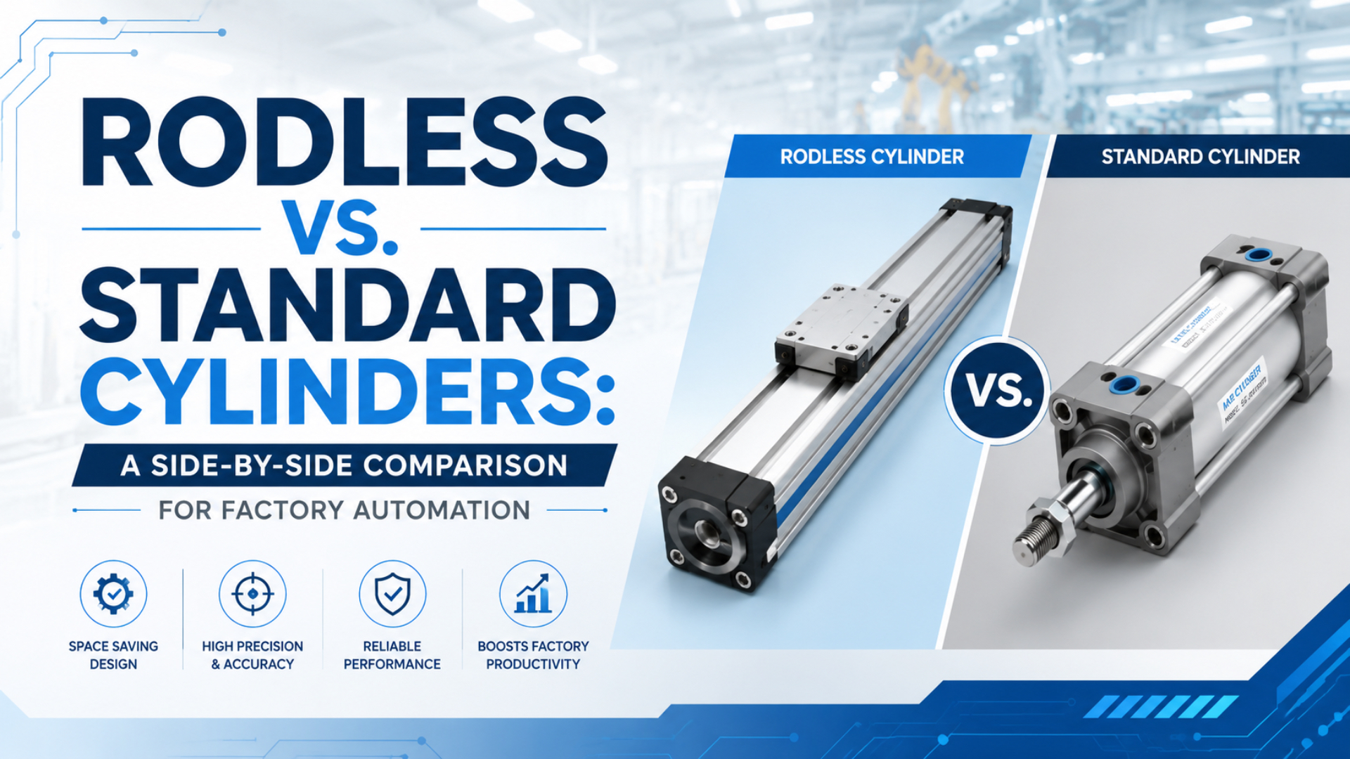
For a long-stroke factory transfer, choose a rodless cylinder when an extending piston rod makes the machine too long or creates an unacceptable buckling case. Choose a standard rod cylinder when the available envelope, supported load, mounting, and service plan all pass with the simpler configured assembly. Bore and headline speed do not decide this comparison by themselves.
This guide compares one duty through five gates: installed envelope, usable force, structural load path, stopping energy, and lifecycle integration. It deliberately does not repeat the broader advantages of rodless cylinders. The goal here is a drawing-ready worksheet for factory automation engineers, buyers, and maintenance teams.
Compare current manufacturer catalogs, ISO pages, safety rules, and purchasing requirements before choosing between rodless and standard cylinders. Every product value must stay tied to the named series and stated conditions.
Installed axial envelope is the complete stroke-axis space required by the configured actuator, moving elements, guards, and service access. Theoretical cylinder force is pressure multiplied by active piston area before losses. Critical buckling load is the ideal axial load at which a slender compression member loses straight-line stability.
Short Answer: Select by Envelope and Load Path
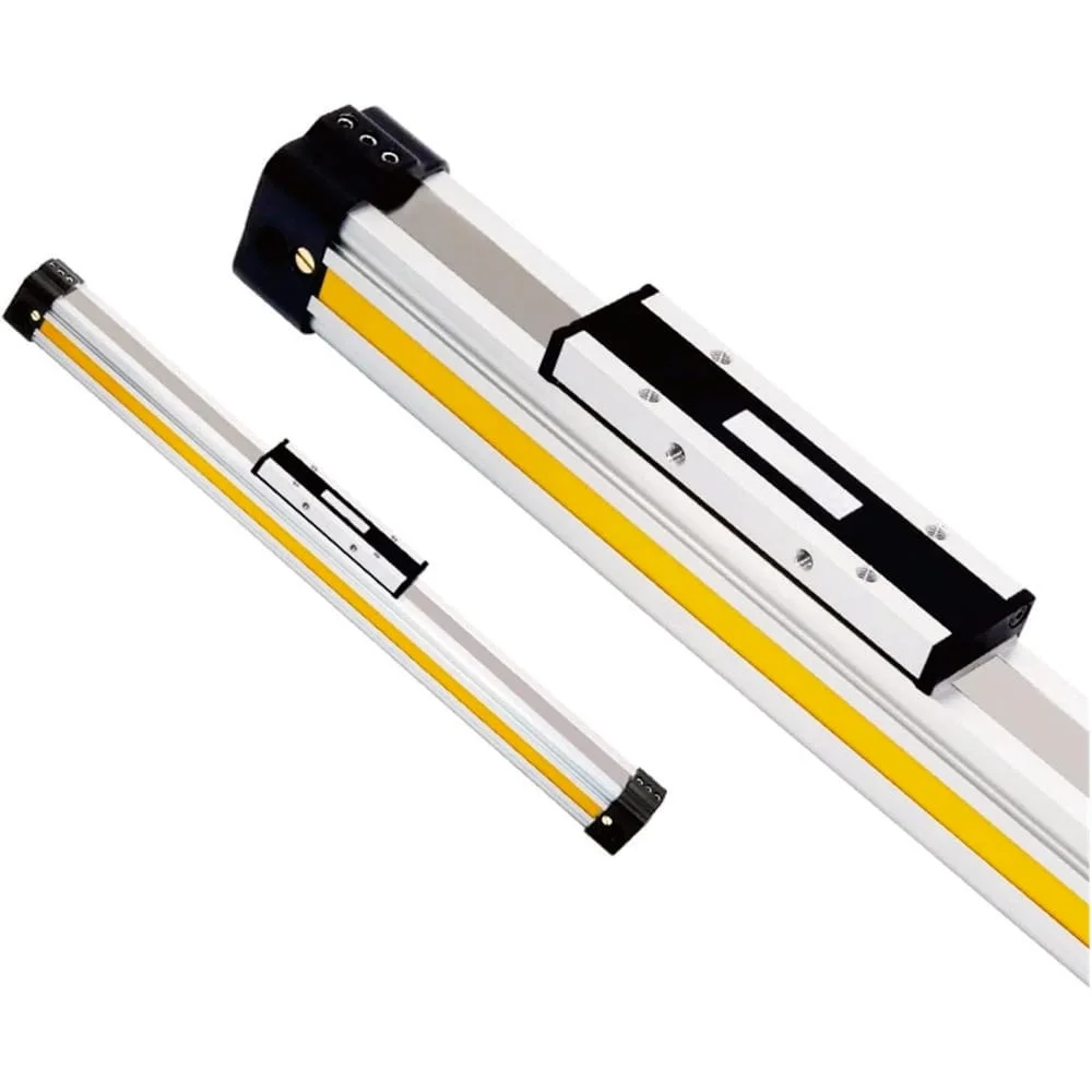
Choose between the two designs by checking installed envelope and load path before comparing catalog thrust. Parker’s OSP-P catalog lists rodless strokes up to 6,000 mm in 1 mm increments, while ISO 15552 covers standard cylinders with 32 to 320 mm bores rated to 1,000 kPa. Neither specification alone identifies the safer machine layout.
Key Takeaways
- At 6 bar, Parker lists 1,178 N theoretical force for both compared 50 mm examples.
- Rod-style axes need buckling checks; rodless axes need carriage-moment checks.
- Compare dynamic pressure, envelope, moving mass, stopping energy, guarding, and access.
- Buy the design that passes every gate at lower site-specific lifecycle cost.
A rodless design is a strong candidate when the carriage can support the load and the stroke-axis envelope is the binding constraint. In contrast, a standard design is a strong candidate when a rod projection fits, the compression rod has enough buckling margin, and an external guide or supported tooling already carries side load.
How Should You Compare Both Cylinders on the Same Duty?
Compare both candidates at the same stroke, payload, cycle time, mounting orientation, working pressure, and end conditions. Parker publishes 1,178 N theoretical extension force at 6 bar for both its 50 mm P1F standard cylinder and 50 mm OSP-P rodless cylinder, making geometry and load support the meaningful differentiators in this example.
Freeze the duty before requesting prices. For example, if one quotation assumes static regulator pressure and another uses pressure measured at the cylinder during motion, the comparison is already invalid.
| Same-duty input | Record this value | Why it cannot vary between candidates |
|---|---|---|
| Required stroke | Travel, mm | Sets body, rod projection, support, and air volume |
| Moving mass | All moving parts, kg | Sets acceleration and stopping energy |
| Load center | X, Y, and Z offset from rod joint or carriage center | Creates side load and moments |
| Orientation | Horizontal, vertical, inclined | Changes gravity load and stored-energy controls |
| Motion profile | Stroke time, dwell, cycles per minute, end velocity | Sets flow, acceleration, and cushion demand |
| Dynamic pressure | Lowest pressure at the working port during motion | Sets usable thrust |
| Guidance | External rail, guided carriage, or supported tooling | Determines the structural load path |
| Environment | Dust, washdown, temperature, chemicals, clean area | Changes sealing, protection, and inspection needs |
| Machine envelope | Body, projection, guards, tubes, sensors, and service clearance | Determines whether the assembly fits |
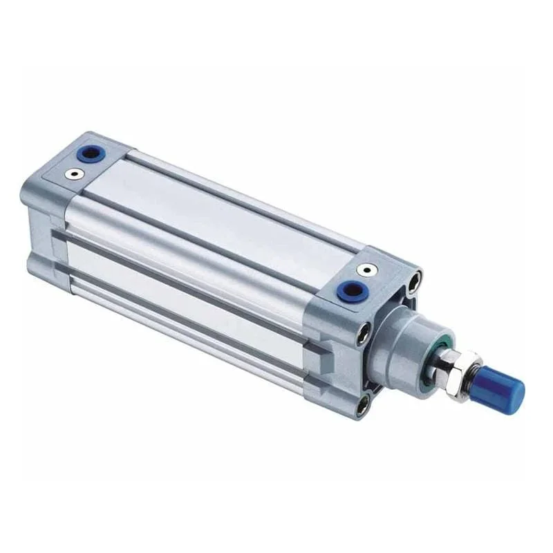
For theoretical force, start with F = pA, then deduct friction, backpressure, and the design reserve. On retraction, a single-rod cylinder uses the annular piston area because the rod occupies part of the area. The pneumatic cylinder force and air-use formulas explain those calculations in more detail.
When Does Machine Envelope Decide the Winner?
Machine envelope decides the choice when the extending rod, rear service space, or carriage clearance conflicts with guards and adjacent equipment. Parker defines OSP-P basic body length as stroke plus twice dimension A and offers strokes to 6,000 mm; final clearance must still come from the selected model’s dimension drawing and machine layout.
The procurement drawing should compare installed axial envelope, not cylinder body length. A rod-style layout needs room for the retracted body, the full external rod travel, and service or guarding clearance. A rodless layout has no projecting piston rod, but its end caps, mounts, carriage, cable carrier, shock absorbers, tubing, and service access still occupy space.
We tested both layouts with one transparent 1,200 mm worksheet. It assumes a 300 mm dead-length allowance for the standard cylinder, a 360 mm combined end allowance for the rodless body, and 120 mm equal clearance. These are worksheet assumptions, not catalog dimensions for a selected model.
For this stated geometry, the rod-style total is (1,200 + 300) + 1,200 + 120 = 2,820 mm. The rodless total is (1,200 + 360) + 120 = 1,680 mm. The modeled difference is 1,140 mm, or 40.4% of the rod-style envelope. That result belongs only to these declared assumptions.
How Do Thrust and Load Path Differ?
Equal bore and pressure can produce equal theoretical thrust, but they do not create the same structural load path. At 6 bar, Parker lists 1,178 N theoretical extension force for both 50 mm examples; the P1F retracts at 990 N, while the OSP-P lists 1,000 N effective force under its stated catalog conditions.
Force generation and force transmission are separate decisions. Pressure acting on piston area generates thrust. The piston rod, rod-end joint, carriage, guide, mounting structure, and load offset determine how that thrust reaches the payload without buckling, binding, or exceeding a moment rating.
| Check | Standard rod cylinder | Mechanically coupled rodless cylinder |
|---|---|---|
| Force path | Piston to rod to rod-end joint | Piston to internal coupling to external carriage |
| Retraction area | Reduced by rod area | Product-specific, check both directions |
| Primary long-stroke structural check | Compression buckling of the extended rod | Tube support and carriage or guide loads |
| Side load | Keep off the rod with external guidance | Check the selected carriage guide or add external guidance |
| Offset payload | Loads the rod joint and external guide | Creates carriage forces and moments |
| Alignment | Rod, bearing, tooling, and guide must not bind | Body, carriage, guide, and tooling must remain parallel |
Some rodless cylinders are magnetically coupled; others are slotted and mechanically coupled, with or without an integrated guide. The article on magnetic, mechanically jointed, cable, and guided rodless types explains the construction differences.
For a guided rodless slide, test all simultaneous forces and moments using the coordinate system in the selected catalog. Festo’s DGC guidance requires the normalized combination of Fy, Fz, Mx, My, and Mz to remain at or below 1, including dynamic loads during deceleration. The full rodless-cylinder guide moment and load-path check belongs in that dedicated sizing step.
Do not compare the P1F’s 990 N retraction value with the OSP-P’s 1,000 N effective value as if they were the same metric. One is a direction-specific theoretical rod-cylinder value; the other is Parker’s effective-force listing for that rodless series. Final usable force needs the actual direction, dynamic pressure, friction, acceleration reserve, and manufacturer method.
When Does Piston-Rod Buckling Set the Limit?
Check piston-rod buckling before accepting a long-stroke standard cylinder in compression. Parker’s P1F example limits a 50 mm bore, 20 mm rod cylinder carrying 0.5 kN at 6 bar to a 1,450 mm stroke when a fourfold buckling safety factor is applied; actual limits depend on mounting and manufacturer data.
Euler’s ideal-column relation is Pcr = π²EI/(KL)². For a solid circular rod, I = πd⁴/64. The formula explains two powerful sensitivities: diameter enters to the fourth power, while effective unsupported length enters squared in the denominator. It is an explanation tool, not a substitute for a cylinder maker’s buckling chart.
The line chart uses a 20 mm solid steel rod, E = 210,000 N/mm², pinned ends with K = 1, and no safety factor. The equations follow the MIT OpenCourseWare column-buckling reference.
Doubling unsupported length from 1,000 to 2,000 mm reduces this ideal critical load from 16.278 kN to 4.070 kN, one quarter of the original value. Real rod-end threads, bearing clearances, misalignment, shock, side load, and mounting conditions lower confidence in the ideal result. Use the chosen manufacturer’s allowable curve and safety method.
What Sets Safe Speed and End-of-Stroke Energy?
Safe speed is governed by moving mass, end-of-stroke energy, cushioning capacity, and valve flow, not by actuator type alone. SMC rates the MY1B at 100 to 1,000 mm/s in its base range and permits up to 1,500 mm/s only with specified adjustment units, while requiring operation within the applicable absorption-capacity limit.
Kinetic energy is E = 1/2 mv², so doubling end velocity quadruples the energy that the cushion, shock absorber, stop, mounting, and guide must absorb. Average stroke speed is not enough. Parker’s OSP-P selection guidance notes that speed at the start of cushioning is typically about 50% higher than average for that series and calls for additional shock absorbers when its chart limit is exceeded.
Check stopping in this order:
- Calculate total moving mass, including carriage or rod-side tooling.
- Establish measured or simulated velocity at cushion entry.
- Check the selected cylinder’s permissible cushion energy and adjustment range.
- Add external shock absorbers or reduce speed when the catalog limit fails.
- Confirm valve flow, tube size, exhaust restriction, dynamic pressure, and cycle temperature.
- Verify that the guide and mounts tolerate deceleration forces and moments.
The same method applies to both architectures. Festo’s DSBC data, for example, lists model-specific maximum end-position impact energy from 0.4 J at 32 mm bore to 3.3 J at 125 mm bore. Those values do not prove that a larger bore cures an aggressive stop, because moving mass also changes. Use the dedicated guide to end-of-stroke cushion energy and tuning for the detailed procedure.
Installation, Maintenance, and Safety
Installation and maintenance requirements should be compared as tasks, hazards, and access needs rather than as a universal winner. CAGI reports that most well-designed systems have no more than 10% pressure drop from compressor discharge to point of use, and OSHA 29 CFR 1910.147 requires stored pneumatic energy to be relieved or restrained before servicing begins.
| Work item | Standard rod cylinder | Slotted rodless cylinder |
|---|---|---|
| Alignment | Keep rod, rod bearing, tooling, and external guide coaxial | Keep body, carriage, guide, supports, and tooling parallel |
| Guidance | Do not use the rod as a side-load bearing | Confirm integrated guide rating or install an external guide |
| Long-stroke support | Check rod buckling and external guide support | Check extrusion support spacing, deflection, and oscillation |
| Routine inspection | Rod surface, wiper, seal leakage, joints, mounts, switches | Bands, wipers, carriage, guide, mounts, supports, switches |
| Contamination control | Protect exposed rod and seals | Protect slot, bands, carriage, and guide as the model requires |
| Replacement access | Leave room to withdraw rod-side parts or the cylinder | Leave room to remove carriage, bands, seals, or guide parts |
Neither design is universally easier to maintain. Parker’s OSP-P operating instructions include band, wiper, seal, and carriage tasks plus a model-specific 8,000 km service point. A standard-cylinder manual adds rod-surface, joint, alignment, leakage, and filter checks. Build the site plan from the selected manual, environment, cycle count, inspection results, and the rodless-cylinder preventive maintenance checklist.
Guard the carriage or rod, attached load, end stops, and every pinch or crush point across the complete swept envelope. OSHA 29 CFR 1910.212 establishes machine-guarding duties in U.S. workplaces. ISO 4414 provides broader pneumatic-system safety guidance across design, installation, operation, and maintenance. Apply the machinery law and standards required at the installation site.
Before service, isolate every energy source, bleed trapped air, restrain gravity loads, and verify the zero-energy condition. Closing the supply valve alone can leave pressure in the cylinder, tubing, or accumulator. Use slow pressurization during commissioning and confirm that cushions, speed controls, guards, sensors, and stops work before releasing production.
A Long-Stroke Transfer Selection Worksheet
Use a worksheet that converts the duty into checkable catalog inputs before requesting quotations. Parker recommends a rod-buckling safety factor between 3.5 and 5 for its P1F selection method, while NIST’s equipment guide frames purchasing across five stages: financing, installation, use, maintenance, and disposal. Record assumptions separately from supplier-confirmed limits.
| Gate | Worksheet entry | Pass condition | Evidence to retain |
|---|---|---|---|
| 1. Same duty | Stroke, mass, load center, orientation, motion profile, dynamic pressure | Both concepts use identical inputs | Approved duty sheet |
| 2. Envelope | Configured body, projection, carriage, mounts, tubes, sensors, guards, service clearance | Assembly fits in every position | Dimension drawing or CAD overlay |
| 3. Force | Extension and retraction force at lowest dynamic pressure | Required force plus stated reserve is available | Calculation and pressure trace |
| 4A. Rod path | Rod diameter, unsupported compression length, mounting factor, guide | Buckling and side-load limits pass | Manufacturer buckling chart |
| 4B. Rodless path | Carriage forces, load offsets, combined moments, support spacing | Every static and dynamic guide limit passes | Manufacturer load calculation |
Continue with the motion, safety, lifecycle, and commercial gates:
| Gate | Worksheet entry | Pass condition | Evidence to retain |
|---|---|---|---|
| 5. Stop | Total moving mass, cushion-entry speed, energy, external stop | Cushion or shock absorber remains within rating | Energy calculation |
| 6. Air path | Valve flow, tube ID and length, fittings, exhaust, duty | Pressure and speed remain stable during motion | Schematic and measured trace |
| 7. Safety | Guarding, lockout, gravity restraint, safe exhaust, restart | Risk controls meet site requirements | Risk assessment and validation |
| 8. Lifecycle | Access, spares, cleaning, inspections, training, replacement time | Maintenance plan is practical | Manual, parts list, service plan |
| 9. Commercial | Configured hardware, integration, installation, downtime, disposal | Quotes share the same scope | Supplier quotation matrix |
From our analysis, the preferred actuator is the one with the fewest unresolved engineering assumptions, not the shortest feature list. Mark each row pass, recheck, or supplier confirmation required. A low component price is not comparable when guidance, shock absorbers, guards, supports, commissioning, or replacement access is missing from one quotation.
Use a site-specific cost equation:
Total installed cost = configured actuator + guide and load hardware + controls and air hardware + guarding and safety hardware + structure and mounting + installation and commissioning
Then add measured air use, leakage, inspection labor, service parts, expected downtime, spare lead time, and disposal. The DOE compressed-air sourcebook recommends baselining pressure, flow, power, duty, and leaks, and supporting projected savings with calculations and vendor quotations. Do not use a generic purchase premium or payback period.
For supplier review, compare the standard-cylinder product family and rodless-cylinder product family only after the worksheet inputs are frozen. Send the same drawing and duty sheet with both requests.
What Do Engineers Ask About Rodless vs. Standard Cylinders?
Answer model-specific questions about force, side loading, guidance, mounting, speed, cushioning, and service access. ISO 15552 standard-cylinder dimensions cover 32 to 320 mm bores at rated pressures up to 1,000 kPa, whereas Parker’s OSP-P stroke offering reaches 6,000 mm; these ranges describe different design constraints, not a universal winner.
Are rodless cylinders always more compact than standard cylinders?
A rodless cylinder usually needs less axial space because no piston rod extends beyond the barrel. The final machine envelope still depends on end allowances, mounting hardware, carriage clearance, sensors, tubing, guarding, and service access.
Does the same bore produce the same force in rodless and standard cylinders?
Theoretical extension force can be similar at the same bore and pressure. Usable force differs because of seal friction, pressure loss, operating direction, and safety margin. A standard cylinder also has lower retraction force because the rod reduces the effective piston area.
When is a standard pneumatic cylinder the better choice?
A standard cylinder is often suitable for short or moderate strokes, simple push and pull motion, externally guided loads, familiar mounting arrangements, and plants that prioritize common spare parts. Confirm that piston-rod buckling, side loading, and installed length remain acceptable.
When should an engineer choose a rodless cylinder?
A rodless cylinder is a strong candidate for long-stroke transfers where axial space is limited and a moving carriage is useful. Selection must still verify guide capacity, combined moments, stopping energy, speed, cushioning, contamination protection, and maintenance access.
What information should a rodless or standard cylinder RFQ include?
State the required stroke, moving mass, orientation, available pressure, target speed, cycle rate, mounting arrangement, load offset, external guidance, required cushioning, environment, port and sensor preferences, available machine envelope, and applicable safety requirements.
Conclusion: Decide by Envelope and Load Path
Decide by installed envelope, supported load path, buckling margin, stopping energy, and service access, then validate the selection against the chosen manufacturer’s data. Parker’s two 50 mm examples each produce 1,178 N theoretical extension force at 6 bar, yet their retraction, guidance, moment, and envelope checks remain different. Equal thrust does not mean interchangeable designs.
A rodless cylinder wins when its shorter stroke-axis layout solves a real machine constraint and its carriage, support, air path, and stopping checks pass. A standard cylinder wins when its rod projection fits and its buckling, guidance, stopping, and access checks pass with lower installed lifecycle cost. Keep both conclusions conditional on the selected model and measured duty.
Send suppliers one RFQ package containing the duty table, layout drawing, load-center sketch, dynamic pressure, motion profile, stop method, environment, safety requirements, and service-access constraints. That package turns a generic component comparison into a defensible factory-automation decision.
Source Notes
All web sources below were retrieved on 2026-07-10. Catalog values remain model-specific; verify the current configured part number and revision before purchase.
-
ISO 15552:2018, Pneumatic fluid power cylinders with detachable mountings. Used for the 32 to 320 mm bore range and 1,000 kPa rated-pressure scope. ISO marks the edition current after its 2025 confirmation review.
-
Parker OSP-P Pneumatic Rodless Cylinders and Linear Guides, Catalog 0980. Used for strokes, 8 bar maximum pressure, body-length relationship, theoretical and effective force, load checks, cushioning guidance, supports, and operating limits.
-
Parker Pneumatic Cylinders ISO 15552, P1F technical catalogue. Used for the 50 mm force comparison, buckling example, and 3.5 to 5 buckling safety-factor guidance.
-
Festo Linear drives DGC, 2026-05. Used for mechanically coupled rodless construction, model-specific load combinations, and dynamic moment checks.
-
Festo Standards-based cylinders DSBC, to ISO 15552, 2026-04. Used for rod-cylinder construction and model-specific end-position impact-energy examples.
-
Festo General operating conditions. Used for the pressure-area force relationship and the need to deduct friction.
-
SMC MY1B mechanically jointed rodless cylinder catalog. Used for operating pressure, piston-speed conditions, load selection, cushioning, and absorption-capacity limits.
-
MIT OpenCourseWare, Elastic Buckling of Long Slender Columns. Used for Euler’s critical-load formula and the solid circular-section second moment of area.
-
CAGI Pressure Drop Technical Brief. Used for the 10% pressure-drop benchmark reported for most well-designed systems.
-
Parker OSP-P Operating Instructions. Used for commissioning, guarding, depressurization, service tasks, and the model-specific 8,000 km service point.
-
OSHA 29 CFR 1910.147 and OSHA 29 CFR 1910.212. Used for U.S. stored-energy control and machine-guarding requirements.
-
ISO 4414:2010. Used for pneumatic-system safety across design, installation, operation, and maintenance.
-
NIST, Manufacturers: Pre-Purchase Guide for Equipment, 2020-09-09. Used for lifecycle purchasing stages and integration-cost questions.
-
DOE, Improving Compressed Air System Performance: A Sourcebook for Industry, third edition. Used for measured baselines, systems analysis, and evidence-backed savings estimates.
-
AVENTICS, Rodless cylinders – RTC series, uploaded 2017-11-10. Used as the embedded product-construction overview; duration 3 minutes 1 second.