

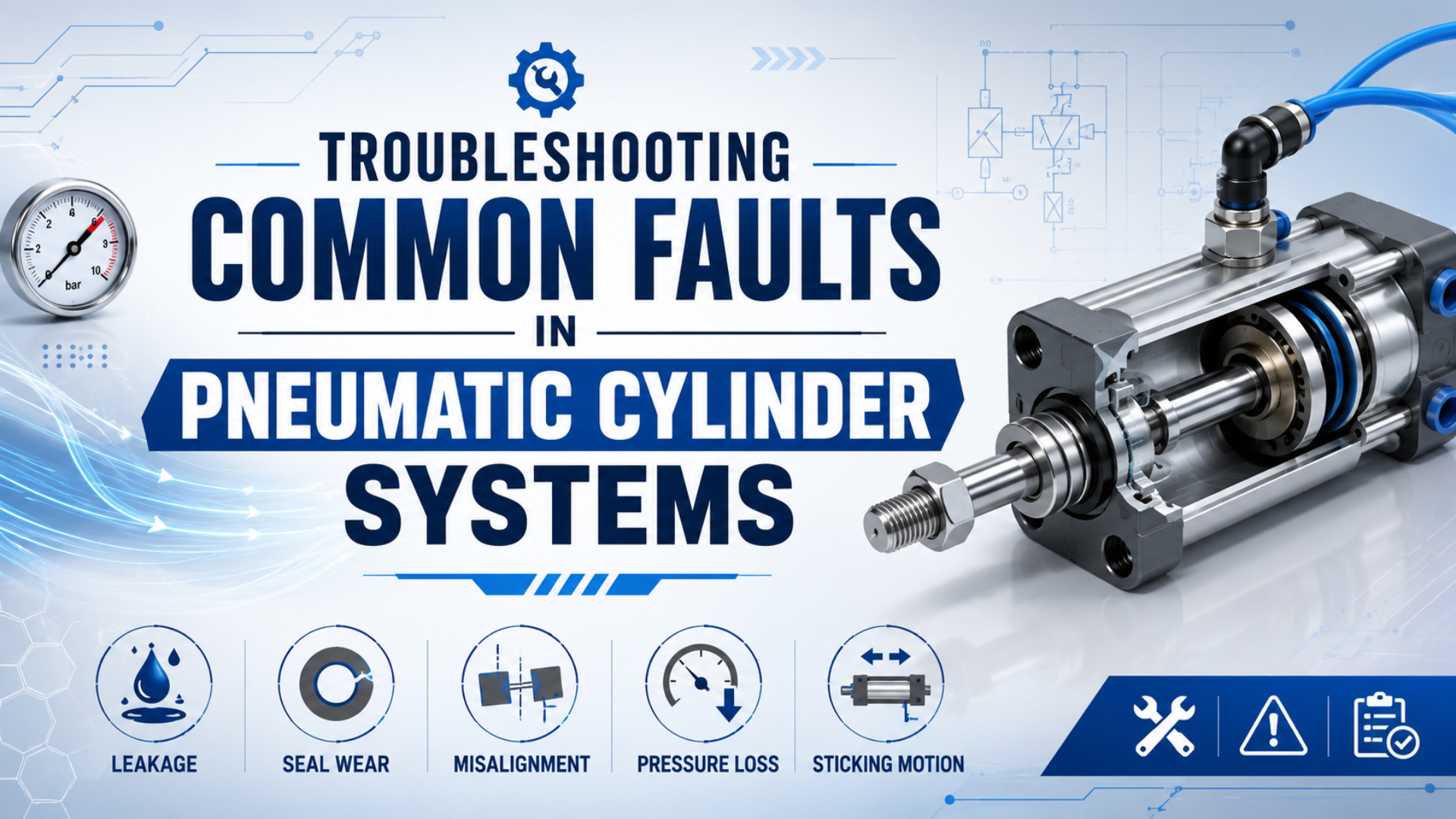
Effective pneumatic cylinder troubleshooting starts by separating the symptom from the failed part. Record when the fault occurs, measure pressure while the cylinder moves, compare extension with retraction, and then decide whether the fault follows the air supply, valve, exhaust path, cylinder, guide, or load.
Start with facts.
That order prevents random replacement. CAGI says a well-designed compressed-air system should keep total pressure drop from compressor discharge to point of use within 10%, so a normal compressor gauge does not prove that useful pressure reaches the actuator during its heaviest stroke (CAGI Pressure Drop Technical Brief, 2022).
Dynamic pressure is the pressure measured while air is flowing and the cylinder is moving under its real load.
Key Takeaways
- Diagnose the operating condition, direction, and load before changing parts.
- Measure dynamic pressure because CAGI’s system target is no more than 10% total pressure drop.
- Treat leakage, contamination, valve flow, exhaust restriction, side load, and cushioning as separate test branches.
What Safety Boundary Applies Before Any Test?
OSHA 29 CFR 1910.147 covers pneumatic energy and requires hazardous stored or residual energy to be relieved, disconnected, restrained, or otherwise rendered safe before servicing. Treat a stopped cylinder as energized until an authorized person isolates the sources, secures suspended or moving loads, relieves trapped pressure, and verifies isolation (OSHA, accessed 2026).
Online observation and invasive service are different jobs. A technician may need the machine energized to watch a gauge, confirm a sensor sequence, or capture cycle time. Opening a circuit, removing a cylinder, loosening a fitting, or entering a hazardous zone requires the site’s approved energy-control procedure and the component manufacturer’s instructions.
ISO 4414:2010 covers significant hazards in pneumatic systems used on machinery, including installation, adjustment, maintenance, reliable operation, and energy efficiency. It does not replace a machine-specific risk assessment, and it does not cover the factory compressor and distribution system as a whole (ISO 4414:2010, 2010).
Never use a directional valve, regulator knob, or PLC stop command as the only isolation point. Trapped air can remain on one side of a piston, and a vertical load can still move after pressure is removed. If the test cannot be performed within the approved procedure, stop and escalate it.
What Should You Record Before Touching the Circuit?
Record four conditions before changing a setting: direction, load, timing, and point-of-use pressure. DOE explains that maximum distribution pressure loss occurs at maximum airflow, while CAGI places the total well-designed system target at no more than 10% from compressor to use point. Those facts make a dynamic reading more useful than a static one (DOE, 2016; CAGI, 2022).
Write down the symptom in plain terms. “Cylinder problem” is too broad. “Extension slows from 0.7 to 1.2 seconds only when two neighboring actuators cycle” identifies direction, timing, and simultaneous demand. Add the commanded valve state, sensor state, load, regulator setting, and pressure at the valve inlet and cylinder port.
We analyzed the manufacturer fault tables to build this diagnostic sequence. Their most useful first split is not “good cylinder or bad cylinder,” but “does the fault follow direction, demand, temperature, or load?” A one-direction fault points toward a valve path or one chamber. A both-direction fault moves supply, guidance, and load higher.
Use the detailed pressure-drop troubleshooting guide when the valve inlet or cylinder-port pressure falls during the fault. If header pressure moves only when several machines cycle, compare the event with the site’s pressure-fluctuation diagnostic method.
Symptom-First Pneumatic Cylinder Troubleshooting
One symptom rarely proves one failed component. Parker’s OSPP operating instructions associate slow or jerky motion with contamination, lubrication, seal condition, speed setting, operating pressure, and cushioning, while its end-impact branch adds overload and damaged cushioning parts. That product-specific table shows why technicians should branch the diagnosis before ordering parts (Parker OSPP Instructions, accessed 2026).
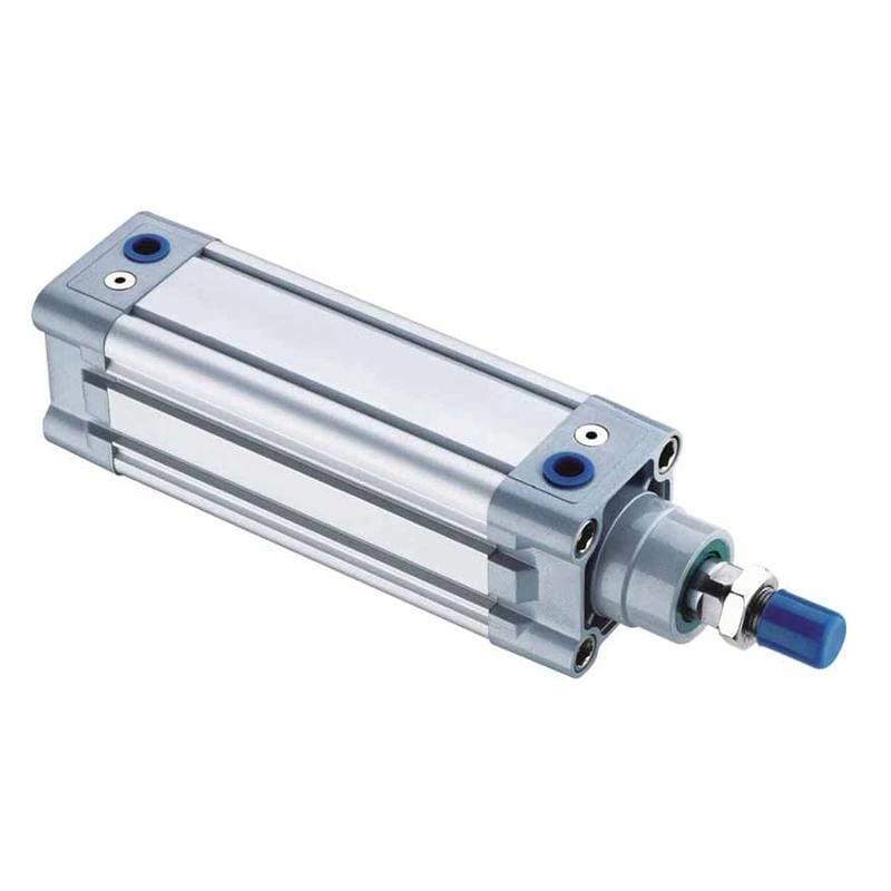
Use this map as a first screen, not as a verdict:
| Observed symptom | First comparison | Likely branches | First measured check |
|---|---|---|---|
| No movement in either direction | Commanded state versus valve indication | Supply isolation, pilot pressure, solenoid, valve spool, mechanical jam | Valve inlet and both work-port pressures |
| No movement in one direction | Extension versus retraction | One valve path, one flow control, blocked exhaust, chamber fault | Compare both port pressures during each command |
| Slow or weak in both directions | Loaded versus unloaded cycle | Dynamic pressure loss, inadequate flow, higher load, excessive friction | Valve-inlet and cylinder-port pressure during motion |
| Slow in one direction | Supply path versus exhaust path | Meter-out setting, muffler, valve exhaust, one tube or fitting | Pressure on the filling and exhausting sides |
| Jerky or sticking | Cold versus warm and loaded versus unloaded | Contamination, poor lubrication, side load, guide binding, low-speed stick-slip | Rod condition, guide alignment, air quality, speed setting |
| Drift, hiss, or loss of hold | Valve isolated versus cylinder isolated | Fitting leak, rod seal, piston bypass, valve leakage | Safe hold test and leak-location check |
| Hard end impact | Normal speed versus reduced speed | Cushion setting, moving mass, speed, failed cushion seal | Stroke speed, load, and cushion response |
For example, a cylinder that retracts normally but stalls on extension does not justify a complete system teardown. Start with the extension valve path, the rod-end exhaust path, the extension load, and the cap-end pressure during motion.
If you need the operating sequence behind these branches, start with how a pneumatic cylinder works in automation. The present article stays focused on isolation and measured decisions rather than repeating the full mechanism.
Why Won’t the Cylinder Move?
SMC’s cylinder-selection guide recommends a load factor of 0.5 or less for dynamic operation, compared with 0.7 or less for stationary work, because seal resistance, bearing resistance, speed, and exhaust reaction reduce useful force. A normal static gauge can therefore coexist with inadequate starting force under real motion (SMC Best Pneumatics Guide, accessed 2026).
Start outside the cylinder. Confirm that the controller is issuing the command and that the solenoid or pilot stage changes state. Then check supply pressure at the valve inlet while the command is active. If pressure reaches the valve but neither work port changes, the fault is more likely in the pilot, coil, wiring, spool, or valve supply than in the actuator.
What if pressure reaches one cylinder port but the piston still does not move? Compare the opposite port. A blocked muffler, closed meter-out control, trapped air, or valve exhaust fault can oppose the commanded stroke. A mechanical jam, misaligned rod coupling, overloaded slide, or seized guide can create the same symptom.
Only after safe isolation should the mechanical path be separated according to the machine procedure. Do not loosen a port to “see if air comes out.” Use approved test points and gauges. The solenoid-valve control guide explains the electrical, pilot, spool, and work-port sequence in more detail.
Why Is the Cylinder Slow or Weak?
CAGI’s 10% system pressure-drop target and SMC’s force relation point to the same check: with piston area and load factor unchanged, a 10% fall in working pressure produces a 10% fall in theoretical cylinder force. Speed is different. It depends on the airflow available to fill and exhaust the chambers during the required stroke time (CAGI, 2022; SMC, accessed 2026).
Pressure drop is the difference between two pressure readings while air is flowing through a resistance.
Place one gauge at the valve inlet and another as close as practical to the working cylinder port. Record both at the moment the motion slows. A steady upstream reading with a falling port reading points toward the regulator, valve, manifold, tube, fitting, or flow control. If both fall together, move upstream toward the FRL, branch, header, receiver, or compressor controls.
Across the pressure and flow branches, we found one quick comparison: force versus speed. Low measured pressure reduces force margin. Normal pressure with slow motion shifts attention toward supply flow, exhaust flow, valve capacity, tubing, and chamber volume.
If pressure stays normal but speed is low, test the flow path. A long narrow tube, low-flow valve, closed flow control, or restricted exhaust can limit chamber filling or emptying. A larger cylinder may increase force yet move more slowly because its volume demand is greater. That is why pressure and flow must be checked separately.
For a one-direction speed fault, inspect the exhaust branch as carefully as the supply branch. Festo explains that back pressure creates an opposing force, and SMC warns that a dirty or clogged muffler can reduce cylinder speed in the valve system it documents (Festo Technical Information, 2009; SMC S0700 Manual, 2022). Use the back-pressure guide for that branch.
Why Is Motion Jerky or Unstable?
CAGI recommends changing filter elements at 5-7 psig differential pressure, while Festo’s maintenance guidance uses 0.4 bar, about 5.8 psi, as a clean-or-replace trigger in its example. The close agreement makes filter restriction a measurable check, but neither number is a universal cylinder-failure threshold (CAGI, 2022; Festo, accessed 2026).
Jerky motion can come from air and mechanics at the same time. Particles increase friction at seals and sliding surfaces. Water can promote corrosion, while unsuitable oil contamination may swell elastomers. ISO 8573-1 classifies compressed-air purity by three primary groups: particles, water, and oil. It does not impose one universal class or one universal dew point on every cylinder (ISO 8573-1, 2010; Festo Compressed Air Preparation, 2023).
Look at the rod and load path. Longitudinal scoring, uneven guide wear, a tight clevis, or a bracket that forces the rod sideways can create stick-slip that no regulator adjustment will cure. Run the unloaded comparison only when the approved procedure allows it. If motion becomes smooth without the machine load, correct alignment or guidance before fitting another seal kit.
Does the problem appear only near the end of stroke? Check cushion adjustment, moving mass, speed, and cushion condition. Parker lists a fully closed cushion adjustment as one reason a piston may not reach the end position, while wrong adjustment, overload, or damaged cushion parts can produce hard impact. These are model-specific clues, not permission to exceed the cylinder’s instructions.
Use the ISO air-quality guide for contamination targets. Use the machine’s flow-control documentation for meter-in and meter-out checks, and the cushioning guide for end-impact diagnosis.
How Do You Separate Valve Leakage from Cylinder Leakage?
DOE’s pressure-decay method uses known system volume, starting pressure, ending pressure, and elapsed time; its published equation also applies a 1.25 correction for falling pressure. Festo likewise calculates leakage from cylinder or total volume and measured pressure change after temperature effects settle. Neither method identifies valve leakage without controlled isolation (DOE, 2016; Festo Leakage Diagnostics, accessed 2026).
Internal leakage means air passes across a piston or valve inside the circuit instead of escaping directly to the surrounding atmosphere.
First locate external leakage with an approved method such as ultrasonic detection or a compatible leak-detection fluid. Check fittings, tube ends, valve exhausts, rod seals, and end caps. A hiss at a valve exhaust does not automatically prove piston-seal bypass because the valve itself can leak internally.
For a hold or decay test, follow the machine’s isolation procedure and the cylinder or valve manufacturer’s instructions. Define the isolated volume, stabilize temperature, record pressure at a consistent point, and prevent production demand from entering the test. Then change one boundary at a time so the leak follows either the valve side, the actuator side, or an external connection.
A repeatable leak number is more valuable than a loudness judgment. It creates a before-and-after repair check. It still does not tell you which seal failed, so combine the result with rod condition, valve isolation, exhaust behavior, and the cylinder-sealing diagnostic guide.
When Should You Rebuild or Replace the Cylinder?
Parker’s cylinder safety guide identifies three serious outcomes of cylinder or control failure: uncontrolled movement, a falling cylinder or supported object, and high-velocity fluid escape. That risk is why no universal “repair at 60% of replacement cost” rule is defensible. Condition, load hazard, parts support, downtime, and validation matter more (Parker Cylinder Safety Guide, accessed 2026).
Use physical evidence to make the decision:
| Inspection result | Rebuild is reasonable when | Replace or seek engineering review when |
|---|---|---|
| Seal leakage with clean running surfaces | The correct seal kit, procedure, and inspection limits are available | Leakage follows a scored rod, damaged bore, distorted gland, or unknown parts |
| Rod condition | The rod is straight and its seal path meets the manufacturer’s finish limits | The rod is pitted, scratched, bent, or damaged where the seal travels |
| Guide or mounting wear | Wear parts can be replaced and the side-load cause is corrected | Permanent deformation, cracked mounting, or recurring one-sided wear is present |
| End-cap or cushion fault | Approved replaceable parts restore the original design | The end cap, cushion bore, threads, or structure are damaged |
| Repeated failure | The root cause is documented and removed before rebuilding | The machine repeats the same fault without a verified load, alignment, air, or control correction |
| Safety-critical or obsolete unit | The manufacturer supports the repair and the result can be validated | Parts provenance, ratings, or post-repair validation cannot be established |
Parker’s service guidance supports seal replacement for normal seal wear, rod replacement when the rod is pitted or scored, and manufacturer engineering review for mechanical breakage or permanent deformation (Parker Cylinder Safety Guide, AC0800.01-T1, 2013). Apply those principles with the actual cylinder manufacturer’s limits.
Before ordering, send the full model code, bore, stroke, rod diameter, mounting, port size, working pressure, load direction, cycle rate, environment, failure photos, and measured symptoms. A replacement that matches only bore and stroke can repeat the original mounting, flow, cushioning, or contamination problem.
Prevent Repeat Failures With Measured Records
DOE reports that well-maintained compressed-air systems can keep leakage below 5-10% of compressor output, while poorly maintained systems may lose 20-30%. Those are plant-system ranges, not allowable leakage for one cylinder, but they show why leak records, pressure baselines, and verified repairs belong in routine reliability work (DOE Sourcebook, 2016).
Build a baseline after the machine is known to be healthy. Record extension and retraction time, dynamic valve-inlet and cylinder-port pressure, load, regulator setting, filter differential pressure, leak location, air-quality observations, rod and guide condition, and the final repair. Keep the same test point and operating condition for future comparisons.
DOE recommends recording initial specifications and operating data, ongoing observations and instrument readings, and the dates and parts involved in maintenance or repair. It also recommends leak records with location, type, size, and estimated cost. Repeated entries for one station should trigger root-cause review rather than another identical parts order.
From our research into maintenance records and fault tables, the closing measurement matters as much as the opening diagnosis. If a repair changes the symptom but does not restore the baseline, the fault is not closed. Record what improved, what did not, and the exact retest condition. That turns the next breakdown into a comparison instead of a fresh guess.
For instance, a new seal kit may stop an audible leak while stroke time remains slow. The follow-up record should keep the leak result and flag the remaining flow or load branch rather than declaring the repair complete.
FAQs About Troubleshooting Pneumatic Cylinder Faults
Use these five answers as decision boundaries, not universal component limits. A static gauge cannot rule out pressure drop, a decay result cannot identify a failed part by itself, and rebuild decisions still depend on safe isolation, dynamic measurements, load risk, and manufacturer instructions (OSHA, accessed 2026; Parker, accessed 2026).
Why won’t a pneumatic cylinder move when the supply gauge looks normal?
A static supply gauge shows pressure with little or no flow. Check the valve inlet and both cylinder ports while the command is active. CAGI’s 10% target covers the whole system, but a local restriction can create a much larger drop. Also verify the solenoid, pilot, spool, exhaust path, and mechanical load.
How can I tell whether a valve or piston seal is leaking?
Locate external leaks first, then use the approved isolation procedure to change one boundary at a time. DOE’s decay method requires known volume, pressure change, and elapsed time. A pressure drop alone does not identify the component. Compare valve-side and actuator-side results, exhaust behavior, rod condition, and temperature-stabilized repeat tests.
Why is a pneumatic cylinder slow in only one direction?
A one-direction speed fault usually narrows the search to one valve path, one flow control, one tube, or the exhaust side. Festo explains that back pressure opposes useful force, while SMC documents speed loss from a clogged muffler in its valve system. Compare both port pressures and inspect meter-out settings.
Does every pneumatic cylinder need a -40 C pressure dew point?
No. ISO 8573-1:2010 defines purity classes for particles, water, and oil at the specified measurement location; it does not impose one class or one dew point on every cylinder. Select the target from the application risk and the component manufacturer’s requirements, then verify it at the relevant point of use.
When should I rebuild instead of replace a pneumatic cylinder?
Rebuild when approved parts and procedures are available, the rod and bore meet inspection limits, and the root cause is corrected. Replace or seek engineering review for scoring, pitting, permanent deformation, cracked mounting, uncertain ratings, or safety-critical damage. Parker’s guidance supports condition-based decisions, not a universal repair-cost percentage.
Sources
The source set prioritizes OSHA 1910.147, ISO 4414:2010, ISO 8573-1:2010, CAGI, DOE, SMC, Parker, and Festo. Numeric ranges remain within each source’s stated scope, and product-specific troubleshooting clues are identified as examples rather than universal limits (ISO 4414:2010, 2010).
David Li’s credentials are carried by the page author system. Site ownership and technical scope are described on the About page, and readers can submit corrections through Contact. Retrieval dates and the scope used from each source are recorded below.
- OSHA: 29 CFR 1910.147, The control of hazardous energy, pneumatic hazardous energy, stored-energy control, and verification of isolation. Retrieved 2026-07-10.
- ISO: ISO 4414:2010 Pneumatic fluid power, machinery pneumatic-system safety scope and hazard-control principles. Retrieved 2026-07-10.
- ISO: ISO 8573-1:2010 Compressed air, particles, water, and oil purity-class framework and measurement-location scope. Retrieved 2026-07-10.
- CAGI: Technical Brief on Pressure Drop, total-system pressure-drop target, piping velocity guidance, and filter differential-pressure guidance. Retrieved 2026-07-10.
- U.S. DOE: Improving Compressed Air System Performance, Third Edition, system pressure loss, leak ranges, pressure-decay calculation, baselining, and maintenance records. Retrieved 2026-07-10.
- SMC: Best Pneumatics Air Cylinder Model Selection Guide, pressure-area-force relationship, extension and retraction area, and dynamic load-factor guidance. Retrieved 2026-07-10.
- SMC: Series S0700 Instruction Manual, product-specific warning that dirty or clogged mufflers can reduce cylinder speed. Retrieved 2026-07-10.
- Festo: Operating conditions and standards in pneumatics, effective force, back pressure, and pneumatic operating-condition context. Retrieved 2026-07-10.
- Festo: Compressed air preparation in pneumatics, pressure and flow roles plus particle, water, oil, seal, and corrosion mechanisms. Retrieved 2026-07-10.
- Festo: Leakage diagnostics, volume, pressure-change, temperature-settling, and isolation requirements for its diagnostic method. Retrieved 2026-07-10.
- Parker: OSPP-Classic and OSPP-Classic-KF Operating Instructions, product-specific fault branches for motion, leakage, contamination, cushioning, and impact. Retrieved 2026-07-10.
- Parker: Cylinder Safety Guide, cylinder failure hazards and fail-safe design context. Retrieved 2026-07-10.
- Parker: Cylinder Safety Guide, Service Bulletin AC0800.01-T1, condition-based seal, rod, structural-damage, and engineering-review boundaries. Retrieved 2026-07-10.
- RS Engineering Insights video: 5 SURPRISING Troubleshooting Tips for Pneumatic Systems, visual troubleshooting demonstrations by a Festo trainer; not used as a component rating source. Retrieved 2026-07-10.
- Gizmo Controllers video: Electro-Pneumatics, practical solenoid-valve and cylinder fault isolation; not used as a safety-limit source. Retrieved 2026-07-10.