

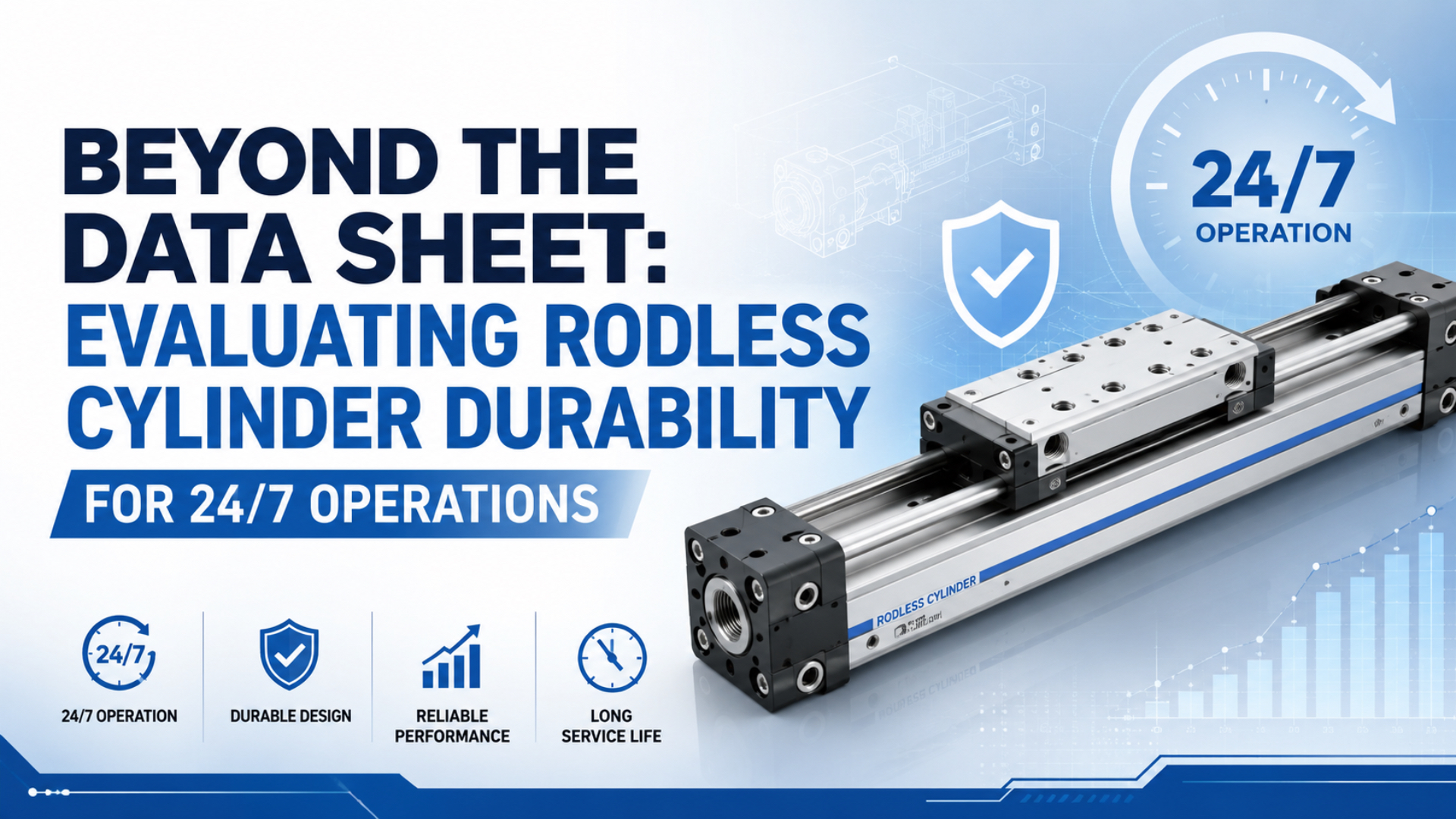
A rodless cylinder is ready for 24/7 operation only when its actual duty profile fits the tested product configuration. A catalog pressure limit or cycle claim isn’t enough. Parker, for example, advertises up to 8,000 km for its OSP-P series, while its own selection notice still makes the user responsible for application endurance, maintenance, safety, and testing (Parker OSP-P series, 2026).
The useful question is not, “Is this a continuous-duty cylinder?” Ask what load, moment, speed, cushion-entry velocity, temperature, contamination class, maintenance allowance, and failure definition produced the claim. Then reproduce those conditions in a pilot test and record a commissioning baseline. That is how a marketing number becomes engineering evidence.
Rodless cylinder durability is the ability of the exact actuator and guide configuration to remain within written performance limits for a defined duty profile. Continuous-duty qualification is the evidence review, representative test, and commissioning process used to decide whether that configuration fits the intended 24/7 application.
Before comparing life claims, identify the actuator family. This guide to rodless pneumatic cylinder types explains why magnetic, mechanically jointed, cable-driven, and guided designs need different qualification evidence.
Key Takeaways
- Parker advertises up to 8,000 km for OSP-P, but the application still requires its own endurance review.
- For the application, translate 24/7 into a recorded duty profile with measurable load, speed, offset, temperature, air-quality, and stopping conditions.
- Supplier evidence must disclose test conditions, maintenance, individual results, and the failure rule.
- Approve production after a representative pilot.
What Does 24/7 Duty Actually Mean for a Rodless Cylinder?
Twenty-four-hour operation is a measurable duty profile, not a catalog grade. Festo lists DGC strokes from 1 to 8,500 mm and maximum speeds up to 3 m/s, while SMC lists MY1M operation from 0.15 to 0.8 MPa and 5 to 60°C (Festo DGC, 2026; SMC MY1, 2025).
Those ranges are envelopes, not life predictions. A slow 500 mm transfer that moves twice per minute and a 5,000 mm shuttle that reverses every two seconds can both run all day. They do not impose the same sliding distance, heat input, guide load, valve demand, or end-of-stroke energy. What exactly is being repeated?
Treat the duty profile as a test contract. Each value should appear in the RFQ, supplier test report, pilot plan, and commissioning record. If one document says “continuous” while the others omit speed or load offset, the evidence chain is already broken.
Annual exposure can be checked before the RFQ leaves your desk. Annual cycles equal cycles/min × 60 × 24 × 365 × utilization. Annual round-trip travel equals annual cycles × 2 × stroke. At 10 cycles/min and a 500 mm stroke, idealized 24/7 operation produces 5,256,000 cycles and 5,256 km of travel per year. State the utilization assumption beside the result.
| Duty input | Record this value | Why it changes durability |
|---|---|---|
| Cycle definition | Extend, dwell, retract, dwell, cycles/hour | Separates calendar time from actual motion |
| Stroke and travel | mm per stroke and km per shift | Converts cycles into sliding distance |
| Moving load | Mass, center-of-gravity offset, orientation | Defines carriage forces and moments |
| Motion | Average speed, peak speed, acceleration, stop method | Sets guide and cushion demand |
| Air path | Dynamic pressure, valve, tube ID, exhaust restriction | Shows whether the cylinder is starved during motion |
| Environment | Ambient and body temperature, particles, water, oil, chemicals | Connects the test to seal, strip, and lubricant exposure |
| Maintenance | Allowed cleaning, lubrication, adjustment, and parts replacement | Prevents hidden test resets |
Supplier tests are incomplete when they report payload but omit offset and stopping conditions. Use these rodless load-path and moment checks to define the missing inputs.
Which Catalog Limits Matter Most for Rodless Cylinder Durability?
Catalog limits matter only with their stated conditions. Parker bases OSP-P load and moment values on speeds at or below 0.5 m/s, and says speed at cushion entry is typically about 50% higher than average piston speed (Parker OSP-P catalog, 2025).
Start with the complete load path. Thrust moves the carriage, but the guide system must carry payload weight and Mx, My, and Mz moments caused by offsets. A passing force calculation can therefore coexist with an overloaded guide. This is common when tooling changes after the original cylinder was selected.
Next, check stop energy. Kinetic energy rises with the square of velocity: E = 0.5 × m × v². The drive can also keep pushing through the cushion stroke, so an engineering check needs moving mass, actual entry velocity, drive force, cushion stroke, cycle rate, and the catalog’s absorption limit. A quiet first cycle proves very little.
| Catalog item | Qualification question | Evidence to retain |
|---|---|---|
| Allowable load and Mx/My/Mz | Do speed, mounting, and offset match the table assumptions? | Calculation sheet and installation drawing |
| Cushion capacity | What are mass and speed at cushion entry, not average speed? | Motion trace, calculator result, adjustment record |
| Pressure range | Is pressure measured at the cylinder during motion? | Dynamic pressure trace at both ports |
| Temperature range | Is the body temperature inside the exact seal and sensor rating? | Thermal log through a representative shift |
| Lubrication | Is the series non-lube, permanently greased, or periodically serviced? | Manual revision and maintenance rule |
| Stroke support | Does the long profile need intermediate supports or a guided carriage? | Deflection and alignment record |
The deeper mechanics are covered in how pneumatic cylinder cushioning works. This article uses that calculation as a qualification input rather than repeating the full sizing method.
How Does Rodless Architecture Change the Failure Evidence?
Architecture decides what should fail first and what must be inspected. SMC’s MY1 family offers five standardized guide types across 10 to 100 mm bores, while Festo lists DGC guide backlash examples of 0, 0.05, and 0.2 mm for different guide designs (SMC MY1 web catalog, 2026; Festo DGC, 2026).
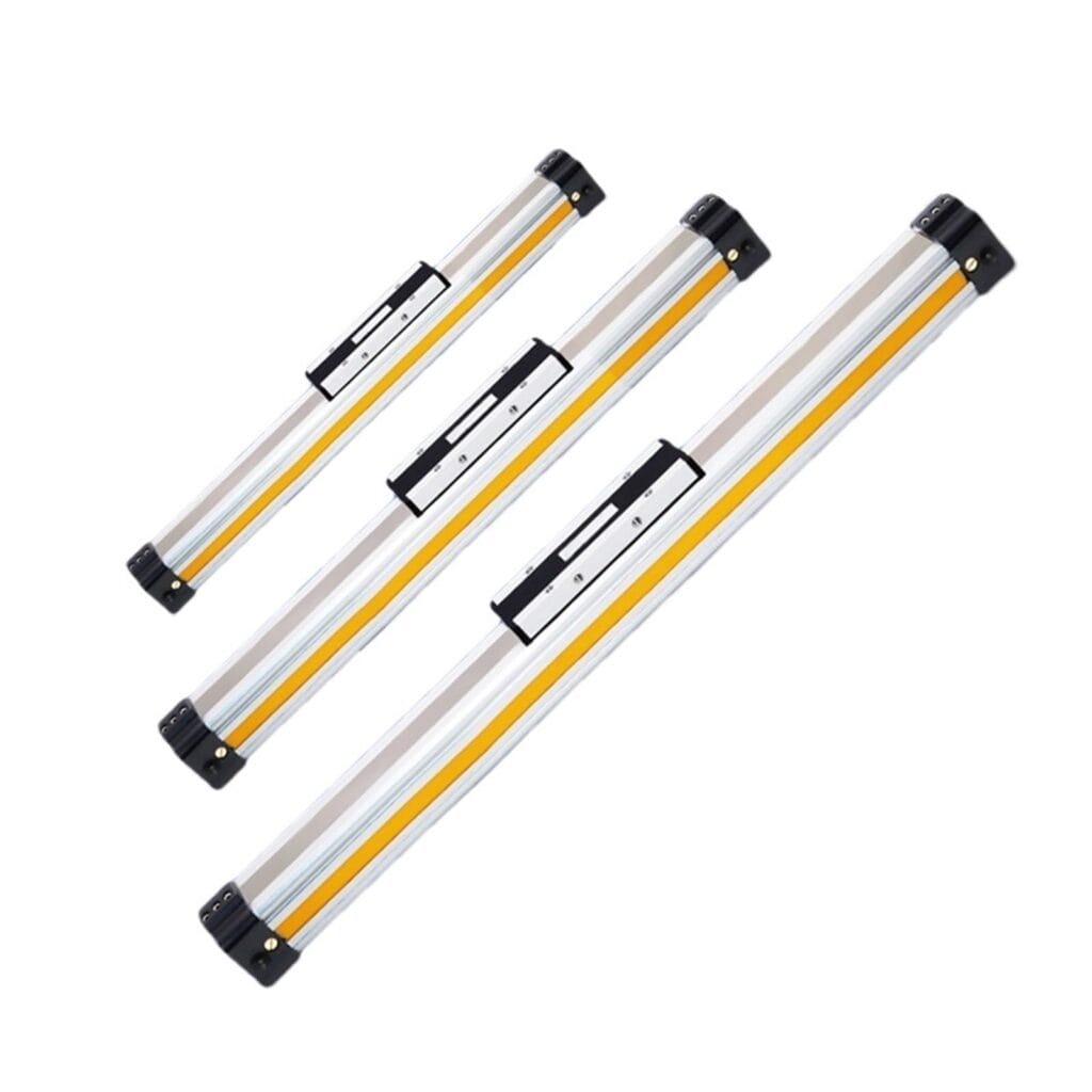
Mechanically jointed cylinders transfer force through a slot and sealing-band system, so their tests should track leakage by carriage position, strip condition, wiper contamination, guide play, and alignment. Magnetic designs have a closed pressure tube, making decoupling margin and external guide behavior more prominent. Guided units add bearing wear and moment capacity to either core design.
| Rodless architecture | Dominant evidence | Common qualification mistake |
|---|---|---|
| Mechanically jointed or slotted | Band leakage, slot cleanliness, carriage alignment, guide moments | Treating a new sealing band as a cure for bad alignment |
| Magnetically coupled | Coupling margin, tube condition, external guidance, load offset | Testing force without checking decoupling during acceleration |
| Guided rodless slide | Bearing play, rail alignment, Mx/My/Mz, stopper impact | Assuming the cylinder body is also an unlimited guide |
| Cable or belt transfer | Tension, pulley condition, repeatability, environmental protection | Applying slotted-cylinder failure logic to another mechanism |
The same pilot plan cannot qualify all four architectures because inspection points and failure criteria must follow the mechanism, even when some generic measurements overlap. For slotted designs, use the guide to rodless cylinder sealing-band failure modes; for heat exposure, use the measured-body-temperature approach in high-temperature pneumatic cylinder selection.
What Evidence Should a Supplier Provide for a 24/7 Claim?
Large life numbers are useful only when their tests can be audited. Parker publishes an OSP-P claim of up to 8,000 km, while ISO 19973-1:2015 requires statistical evaluation because component life varies and applies its method to first failure without repair (Parker OSP-P series, 2026; ISO 19973-1, 2015).
Ask for the exact product code, not a family brochure. Evidence from a guided 40 mm unit with a shock absorber, special seal, and protective cover does not cover an unguided 25 mm unit with air cushions. The report should identify every option that changes the load path, friction, seal package, or stop method.
The strongest supplier evidence package makes comparison boring. You can trace each claim from test sample to setup drawing, operating log, failure definition, and raw result. If the supplier provides only an average or a “passed” label, the buyer inherits an evidence debt that usually appears during commissioning.
| Evidence field | Minimum useful disclosure | Red flag |
|---|---|---|
| Samples | Quantity, model codes, production lot, preconditioning | One unnamed prototype |
| Test profile | Stroke, cycles/min, dwell, load, offset, pressure, temperature | “Continuous cycling” with no numbers |
| Air and environment | Particle/water/oil target, measurement point, chemicals, cleaning | Clean lab air presented as a harsh-environment result |
| Stops and guidance | Cushion or shock model, settings, external guide, mounting flatness | Stop method omitted from the report |
| Maintenance | Cleaning, adjustment, lubrication, interruptions, parts changed | Test clock continues after unreported repairs |
| Failure rule | Leakage, play, speed drift, damage, coupling loss, sensor miss | Failure defined only after catastrophic breakage |
| Results | Individual failures and suspensions, not only the average | Best unit reported as the series life |
| Traceability | Report revision, dates, instruments, calibration, approver | Marketing slide without raw records |
ISO 19973-1 provides a general statistical and reporting framework, not a ready-made rodless-cylinder certification. ISO 19973-3 is specifically scoped to cylinders with piston rods. A supplier may adapt the general framework, but it should explain the adaptation instead of claiming a rodless unit was tested to a scope that doesn’t cover it.
How Should You Run a Representative Pilot or Accelerated Test?
The stop system belongs inside the test boundary. SMC lists shock-absorber capacities from 2.9 to 58.8 J and maximum operating frequencies from 25 to 80 cycles/min for selected MY1 options, while warning that shock-absorber life differs from cylinder life (SMC MY1 with protective cover, 2025).
Start with the production mechanism. Use the intended cylinder model, guide, mounting, payload, offset, valve, tubing, flow controls, sensors, stop hardware, and air treatment. Run long enough to reach thermal stability, then include the fastest production sequence, normal dwells, starts, stops, and expected environmental exposure.
ISO/TR 16194:2017 explains how to develop accelerated life methods, but it does not provide a specific rodless-cylinder procedure. Its published scope covers the same component groups as the ISO 19973 series, including cylinders with piston rods. That makes it a useful warning: acceleration needs a defensible stress-life relationship and must not create a failure mode that production will never see (ISO/TR 16194, 2017).
Use a staged plan:
- Freeze acceptance limits before the first cycle.
- Record zero-hour leakage, stroke time, dynamic pressure, body temperature, sound, carriage play, and sensor repeatability.
- Run the representative profile without maintenance beyond the written allowance.
- At scheduled checkpoints, repeat the baseline measurements under the same sequence. Wait for thermal stability and record the actual load position so each data point remains comparable.
- Photograph strips, guides, stops, fasteners, and contamination.
- Record every interruption, adjustment, part replacement, and suspended sample, including its time and reason.
- Compare the final state with the zero-hour baseline and failure rule.
In our experience, warnings surface early. Stroke time drifts, cushion adjustment reaches its limit, body temperature climbs, or play grows at one load position. If the test records only “running” and “failed,” that warning disappears.
Commissioning Baseline and Go/No-Go Rules
Commissioning should convert pilot evidence into measurable production limits. Festo requires attachment bearing surfaces to be flat within 0.03 mm for one guided DGC configuration and notes that maximum values vary with payload position and mounting position (Festo DGC, 2026).
Capture the first thermally stable shift. This becomes the comparison point for maintenance, not a generic interval copied from another actuator. The baseline should belong to the asset record and identify the exact cylinder, guide, stop, valve, sensor, and software revision.
| Commissioning field | Baseline record | Go/no-go rule |
|---|---|---|
| Dynamic pressure | Minimum pressure at each port during the fastest move | No-go if force margin or timing falls outside the approved window |
| Stroke time | Each direction, average and range | No-go for unstable or drifting motion |
| Cushion behavior | Entry speed, adjustment position, rebound, impact sound | No-go for bottoming, bounce, or exhausted adjustment range |
| Temperature | Ambient, cylinder body, guide, valve, sensor | No-go outside the exact component rating or pilot limit |
| Leakage | Location and measured method | No-go above the written acceptance limit |
| Guidance | Play, alignment, fastener marks, load position | No-go for binding, progressive play, or mounting shift |
| Air quality | Particle, water, oil target and measurement point | No-go when test air and production air are not comparable |
| Safety | Isolation points, stored-energy release, guarded motion | No-go until the energy-control procedure is verified |
OSHA includes pneumatic energy among the hazardous sources covered by lockout/tagout rules for servicing and maintenance. Any inspection that enters the carriage path must follow the site’s energy-control procedure, including relief of stored energy (OSHA Control of Hazardous Energy, 2026).
Use the rodless cylinder maintenance checklist for the post-installation handoff. For contamination limits, document the target and measurement point using the ISO 8573-1 compressed-air quality classes; don’t write “clean air” and assume every party means the same thing.
FAQs About Rodless Cylinder Durability for 24/7 Operations
ISO 8573-1 classifies compressed-air purity around three primary contaminant groups: particles, water, and oil. Parker, SMC, and Festo then add series-specific pressure, temperature, lubrication, load, speed, and cushioning limits, so no single 24/7 interval can replace an application record (ISO 8573-1, 2010).
How many cycles prove a rodless cylinder is durable?
No universal cycle count proves durability. Parker’s OSP-P page advertises up to 8,000 km, but ISO 19973-1 says life varies and needs statistical interpretation. Convert cycles into travel distance, keep individual failure and suspension data, and verify that load, speed, environment, maintenance, and failure criteria match your application.
Can accelerated testing predict 24/7 service life?
It can support a prediction only when the accelerated stress has a validated relationship to normal operation and doesn’t create a different failure mode. ISO/TR 16194:2017 provides development and reporting guidance, not a universal rodless-cylinder test. Ask the supplier to disclose the acceleration model, samples, interruptions, and failure definition.
Is the catalog temperature range enough for continuous duty?
No. Parker lists a standard OSP-P range of -10 to 80°C, while SMC lists 5 to 60°C for MY1M. Those are operating envelopes, not guaranteed life. Measure body temperature after thermal stabilization and confirm seals, lubricant, sensors, cables, and nearby valves against the exact model and option codes.
Which compressed-air quality should the test use?
Use the production target at the point that represents the actuator supply. ISO 8573-1 organizes purity around particles, water, and oil, while also identifying gaseous and microbiological contaminants. Record the class, measurement location, dryer and filter state, lubrication policy, and any chemical or washdown exposure used during the qualification test.
What should trigger a no-go decision at commissioning?
Reject or pause the release when dynamic pressure, stroke time, cushion behavior, temperature, leakage, carriage play, alignment, or safety isolation falls outside the prewritten limit. Festo’s 0.03 mm attachment-flatness note shows why mounting belongs in the baseline. A cylinder that moves once is not automatically qualified for production.
Conclusion: Qualify the Application, Not the Marketing Label
Rodless-cylinder durability comes from matching evidence to conditions. Parker lists 8 bar and -10 to 80°C for standard OSP-P data, SMC lists MY1M at 0.15 to 0.8 MPa and 5 to 60°C, and Festo lists DGC speeds up to 3 m/s (Parker, 2025; SMC, 2025; Festo, 2026).
None of those numbers answers the 24/7 question by itself. Freeze the duty profile, identify the architecture, audit the supplier’s evidence, run a representative pilot, and approve a production baseline with explicit no-go limits. If those records stay aligned, the durability decision is defensible. If they don’t, a larger cycle claim only hides the missing engineering work.
Every retained numeric claim below is linked to an official source or shown as transparent arithmetic. Avoid unsupported percentages and customer-cost stories when qualifying 24/7 rodless-cylinder durability.
Source and retrieval notes
All web sources below were retrieved on 2026-07-10. Product figures are series-specific examples, not universal rodless-cylinder limits.
- Parker: OSPP Rodless Cylinders, up to 8,000 km series claim, application responsibility statement, bore and option context.
- Parker: OSP-P Pneumatic Rodless Cylinders and Linear Guides, 8 bar, -10 to 80°C standard range, load and moment assumptions, cushion-entry speed, lubrication, and stroke data.
- SMC: Mechanically Jointed Rodless Cylinder MY1, pressure, temperature, speed, guide, bore, and shock-absorber conditions.
- SMC: MY1 Web Catalog, five guide types and 10 to 100 mm family bore range.
- Festo: Linear Drives DGC, stroke, speed, pressure, temperature, guide, mounting-flatness, and cushioning data.
- ISO 19973-1:2015, general pneumatic-component reliability procedures, statistical evaluation, and reporting.
- ISO 19973-3:2015, piston-rod-cylinder scope used only to explain why it is not a direct rodless-cylinder certification route.
- ISO/TR 16194:2017, accelerated-life method development and reporting boundaries.
- ISO 8573-1:2010, compressed-air purity classes for particles, water, and oil.
- OSHA: Control of Hazardous Energy, pneumatic stored-energy and servicing context.
- AVENTICS video: Rodless cylinders – RTC series, public manufacturer overview used for the first embed.
- Parker video: How to Adjust the Cushioning for the OSP-P Rodless Linear Actuator, public manufacturer tutorial used for end-cushion commissioning context.