

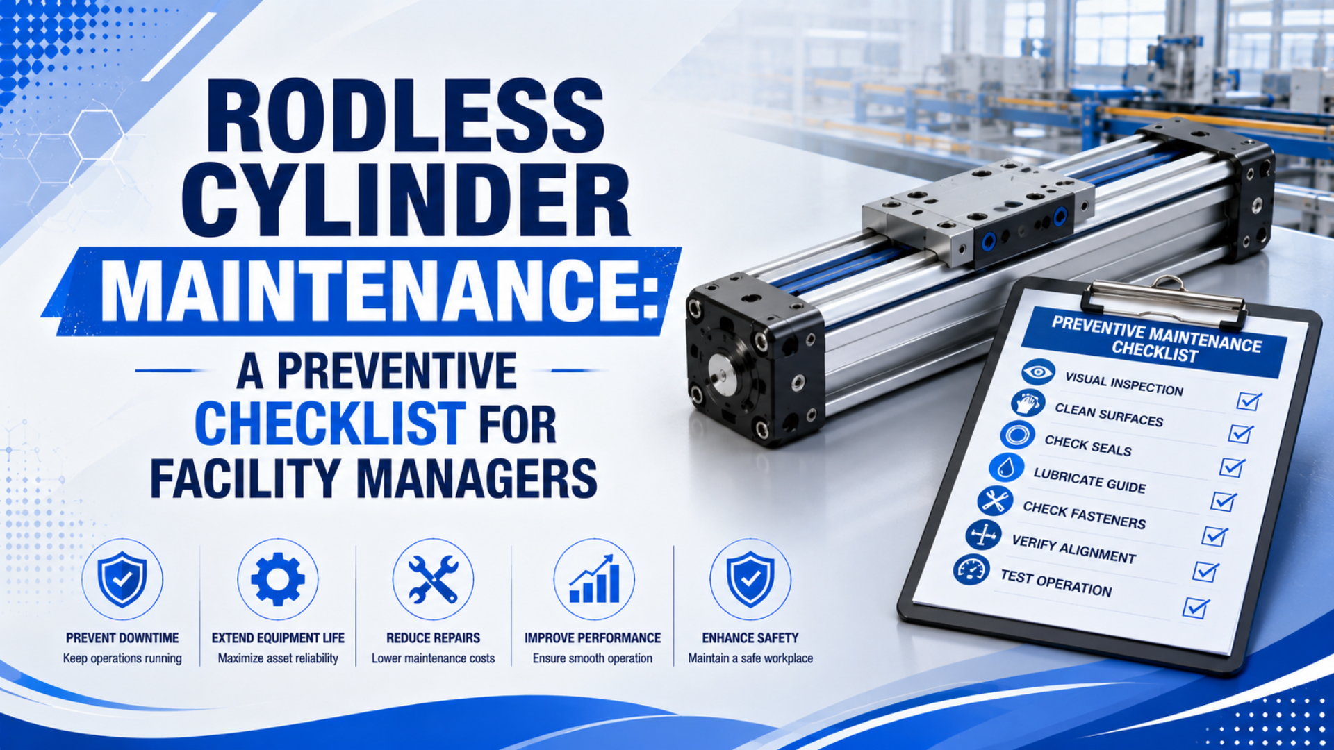
Rodless cylinder maintenance should start with safety isolation, baseline motion data, leak checks, air quality, and the manufacturer’s service notes. It should not start with a universal grease interval. Parker’s OSP-P rodless cylinder data, for example, specifies filtered unlubricated compressed air, permanent grease lubrication, and an 8 bar maximum operating pressure (Parker OSP-P catalog, 2025).
That detail matters. Some rodless cylinders need fresh lubrication at defined points. Others are built around permanent grease and should not receive casual oil mist. If a maintenance sheet treats every rodless actuator the same way, it can create the failure it was meant to prevent.
Rodless cylinder maintenance is the planned inspection, cleaning, air-quality, leak, load, and record process that keeps a rodless pneumatic actuator inside its safe motion baseline. Dynamic pressure is pressure measured while the actuator is moving. Pressure decay testing is an isolated leak test based on volume, pressure drop, and time.
Key Takeaways
- Start with lockout, air isolation, and a baseline stroke record before touching the carriage.
- DOE says compressed air leaks can waste 20-30% of compressor output, so leak checks belong in every PM route.
- Use the rodless cylinder manual for lubrication, seal, guide, and load limits. Don’t invent hour intervals.
In our experience, the most useful maintenance record is not a long checklist. It’s the first clean baseline after installation: supply pressure during motion, stroke time, end-stop sound, carriage play, visible leakage, and the exact load on the slide. Without that baseline, every later fault becomes a debate.
This article is a maintenance-focused companion to the broader guide on what a rodless cylinder is and the system-level comparison of pneumatic and electric actuator maintenance. Use those articles for selection context. Use this one for the facility PM route.
What Should Facility Managers Check First?
Start with the machine risk, not the grease gun: OSHA names pneumatic energy among hazardous energy sources, and Parker lists OSP-P operation around filtered air, permanent grease, and 8 bar maximum pressure (OSHA Control of Hazardous Energy, 2026; Parker OSP-P catalog, 2025).
The first maintenance question is simple: can the technician isolate, vent, test, and restart the axis without surprise movement? A rodless cylinder may carry a pusher, gate, camera, fixture, or shuttle. The carriage can still move after air is removed if gravity, stored mechanical force, tooling weight, or a jammed product releases.
Record the baseline before changing anything:
| Baseline item | How to capture it | Why it matters |
|---|---|---|
| Supply pressure during motion | Gauge or sensor at the machine inlet | Separates air supply problems from cylinder wear |
| Stroke time each direction | PLC timestamp, handheld timer, or sensor log | Shows early drag, leakage, or flow restriction |
| End-stop sound and bounce | Video with audio during normal operation | Catches cushion, shock, and load changes |
| Carriage play | Manual check after lockout and venting | Points to guide, bearing, or mounting wear |
| Visible leak points | Tag fittings, ports, strip areas, and exhaust | Turns a symptom into a repair list |
| Installed load | Record mass, offset, and tooling changes | Prevents guide moment overload after rebuilds |
Don’t skip the installed load. Parker’s OSP-P catalog ties cylinder choice to permissible loads, forces, moments, and cushion performance at the start of cushioning. If the line added heavier tooling after the original install, the “same cylinder” may now be wrong for the job.
Safe Isolation Before Any Maintenance Work
OSHA says hazardous energy can include electrical, mechanical, hydraulic, pneumatic, chemical, thermal, and other energy sources, and unexpected startup or stored-energy release can seriously injure workers during service (OSHA Control of Hazardous Energy, 2026). Rodless cylinder PM must therefore start with energy control.
Use this isolation sequence before inspections that put hands near the carriage path:
- Stop production and clear product from the stroke path.
- Lock out electrical control power where the local procedure requires it.
- Shut off the air supply with a lockable valve.
- Vent downstream pressure and confirm the gauge reads zero.
- Move or support the load if gravity can move it.
- Test for unexpected motion before guards are opened fully.
- Keep the carriage path marked while work is underway.
We’ve found that “vented” is sometimes misunderstood. A branch gauge can read zero while a trapped volume remains between a valve, cylinder port, long tube, or blocked exhaust. For buried rodless axes, add a written bleed point and verify it in the PM route.
Safety checks also protect the article’s technical advice from being misused. A leak test, seal inspection, or carriage cleaning step is not routine if it requires reaching into a pinch point. If the axis is vertical or angled, support the load before loosening anything.
What Should a Daily and Weekly Checklist Include?
DOE and ENERGY STAR report that compressed-air leaks can waste 20-30% of compressor output, and their leak program sequence includes identification, tagging, tracking, repair, verification, and employee involvement (ENERGY STAR compressed-air leak tip sheet, 2000). Make leak detection a scheduled rodless-cylinder task.
Daily checks should be short enough that people actually do them. The point is trend detection, not teardown. Walk the axis while it is guarded and running normally. Listen, watch, and compare the motion against the baseline.
| Frequency | Check | Pass condition | Escalate when |
|---|---|---|---|
| Daily | Listen for new exhaust, hiss, scrape, knock, or squeal | Sound matches baseline video | Noise changes suddenly or repeats every cycle |
| Daily | Watch carriage travel | Smooth motion, no sticking, no bounce | Jerky travel, drift, overshoot, or missed sensor |
| Daily | Check visible fittings and tubes | No loose tube, kink, rubbing, or oil trace | Tube rubs a frame or fitting leaks |
| Daily | Confirm machine inlet pressure | Dynamic pressure stays within the accepted band | Pressure falls only during motion |
| Weekly | Inspect mounting screws and brackets | No looseness or new witness marks | Cylinder body shifts, twists, or vibrates |
| Weekly | Check strip, cover, wiper, or guide path | Clean, seated, and free of trapped debris | Dirt enters the moving interface |
| Weekly | Review recent fault log | No repeated sensor, timeout, or pressure alarms | Same alarm appears more than once |
The daily walk should not include disassembly. If a technician has to remove guards or touch the slide, move the task into the locked-out weekly or monthly route.
For deeper system context, pair this checklist with the guide to FRL and air-source treatment units.
How Should Lubrication and Air Quality Be Managed?
Parker lists OSP-P medium as filtered, unlubricated compressed air and lubrication as permanent grease, while ISO 8573-1 defines compressed-air purity classes for particles, water, and oil independent of where air is measured (Parker OSP-P catalog, 2025; ISO 8573-1, 2010).
That is why the safest maintenance rule is: follow the manual first. If the cylinder is permanently greased, don’t add oil mist because a shift supervisor remembers doing it on a different actuator. If the cylinder has specified grease points, record the exact grease type, amount, date, running hours, and observed condition.
Use this decision table instead of a fixed hours-only schedule:
| Condition | Maintenance response | Why |
|---|---|---|
| Manual says permanent grease | Do not add oil mist unless the maker approves it | Extra oil can carry dirt or affect seals |
| Manual defines grease points | Use only the specified lubricant and amount | Over-greasing can collect abrasive debris |
| Food or pharmaceutical area | Use registered lubricant where incidental contact risk exists | NSF’s nonfood compounds program covers lubricant registration categories |
| Dirty, wet, or dusty area | Shorten inspection intervals and protect the guide path | Contamination reaches wipers, strips, and seals |
| Slow-speed sticking | Check load, alignment, pressure, and specified slow-speed grease | Grease alone may hide a load problem |
| Repeated seal wear | Test air quality at point of use | Water, oil, and particles can reach the actuator after the dryer |
Air quality belongs in the same record. The article on ISO air quality standards for pneumatic systems covers class selection. For a facility PM sheet, the practical question is narrower: is the air at the valve manifold and actuator port still clean, dry, and stable enough for this rodless cylinder?
The failed part often tells the air story. Rust or water in a port points toward moisture. Black paste around a guide path can mean oil plus dust. A clean cylinder that becomes weak only during fast motion often points toward pressure drop, not lubrication.
When Do Warning Signs Require Shutdown?
CAGI says most well-designed compressed-air systems should have no more than 10% pressure drop between compressor discharge and point of use, and it recommends changing filter elements when differential pressure exceeds 5-7 psig or at least every six months (CAGI pressure-drop brief, 2026).
A rodless cylinder does not need to break before it needs attention. Some warning signs can wait for the next planned window. Others justify stopping the machine because the next cycle could damage the carriage, strip, guide, load, or guarding.
| Warning sign | Likely fault group | Action |
|---|---|---|
| Sudden new scraping, grinding, or metal contact | Guide, strip, debris, misalignment | Stop and inspect under lockout |
| Carriage binds, hesitates, or jumps | Side load, dirt, pressure sag, coupling slip | Stop if repeated or load is at risk |
| Visible air leak at strip, port, or end cap | Seal, fitting, band, damaged surface | Tag, quantify, and repair by risk |
| Pressure falls only during stroke | Filter, regulator, valve, tubing, muffler, leak | Measure dynamic pressure at points |
| End impact becomes louder | Cushion, shock absorber, speed, load change | Reduce speed and inspect stop method |
| Sensor misses or drifts | Magnet, switch, cable, bracket, loose carriage | Inspect before increasing pressure |
| Heat or odor appears | Friction, overloaded guide, blocked exhaust | Stop if temperature rises each cycle |
Don’t solve every warning sign by increasing pressure. CAGI calls raising compressor discharge pressure a costly first response when pressure is insufficient at a point of use. First measure. Then repair the largest local restriction or leak.
For a more detailed diagnostic path, use the guide on pressure drop in pneumatic systems and the mechanism-level guide to how a rodless air slide works.
Maintenance Records That Prevent Repeat Failures
DOE and ENERGY STAR recommend that a leak-prevention program include identification, tagging, tracking, repair, verification, and employee involvement, with 5-10% of total system flow as a typical cost-effective leak-reduction target for industrial facilities (ENERGY STAR compressed-air leak tip sheet, 2000).
That structure works for rodless cylinder maintenance too. The record should prove what changed, who checked it, and whether the fault stayed fixed after restart. A checklist without verification is just a memory aid.
Minimum record fields:
- Machine name, cylinder model, bore, stroke, mounting orientation, and serial or asset number.
- Date, shift, running hours, cycle count if available, and technician name.
- Dynamic inlet pressure, stroke time, fault code, and sensor arrival data.
- Leak location, detection method, and repair priority.
- Lubricant type and amount, only when the manual requires lubrication.
- Parts replaced, part numbers, supplier, and old-part condition.
- Root-cause note: leak, contamination, overload, misalignment, pressure drop, sensor, valve, or unknown.
- Verification result after repair: pressure, stroke time, leak check, sensor check, and production restart status.
We’ve seen repeat failures disappear after one small record change: adding “old-part condition” beside “part replaced.” A seal kit entry says the job is done. A note saying “seal cut on one side, guide rail scratched” points to the real cause.
What Data Should You Send for Repair or Replacement?
Parker’s OSP-P tables separate bore sizes from 10 to 80 mm, effective force at 6 bar, permissible moments, load, and cushion length, which is why a replacement request needs more than a photo and stroke length (Parker OSP-P catalog, 2025).
Send the failure evidence with the sizing data. If the old unit leaked because the strip was damaged by debris, a direct replacement may fail again. If it bound because the load offset changed, a new seal kit won’t fix the guide moment. If it slowed down after a filter change interval was missed, the air system belongs in the review.
For repair or replacement, include:
- Old model code, bore, stroke, port size, sensor type, and mounting style.
- Moving mass, load offset, orientation, speed target, and duty cycle.
- Working pressure at rest and during motion, measured near the machine.
- Valve type, tube ID, tube length, flow controls, mufflers, and local FRL details.
- Environment: dust, chips, washdown, heat, chemical exposure, or food area.
- Failure symptom: leakage, bind, hard stop, sensor miss, drift, decoupling, or guide play.
- Photos of the cylinder, carriage, mounting, fittings, guards, and failed parts.
- Baseline and current stroke time if available.
For magnetic designs, add the load and contamination details from the magnetic rodless cylinder guide. For mechanically coupled or guided units, add strip, wiper, guide, and moment-load evidence.
If the facility is replacing a repeated-failure unit, don’t ask only for a cheaper part. Ask for the failure mode review. The better replacement may be a different guide package, cover strip, seal material, support spacing, valve flow path, or air-treatment change.
Conclusion
Rodless cylinder maintenance works when it connects OSHA energy control, DOE leak economics, ISO 8573-1 air-quality thinking, CAGI pressure-drop limits, and the cylinder maker’s manual into one repeatable route (OSHA, 2026; ISO 8573-1, 2010).
The practical rule is boring, which is why it works: isolate safely, compare against baseline, inspect leaks and motion, follow the manual for lubrication, measure pressure under flow, and verify every repair. If the same fault returns, treat it as a system problem, not just a cylinder problem.
FAQs About Rodless Cylinder Maintenance
These answers use the same source set as the main article: Parker for rodless cylinder operating limits, OSHA for pneumatic hazardous energy, DOE and ENERGY STAR for compressed-air leak impact, ISO for air-quality classes, and CAGI for pressure-drop targets and filter differential-pressure guidance.
How often should a rodless cylinder be maintained?
Use the manufacturer manual, duty cycle, environment, and baseline trend instead of a universal hour count. Daily observation can catch noise, leakage, and motion changes. Hands-on checks should happen in locked-out maintenance windows. Lubrication frequency should come from the cylinder manual, not from a generic PM template.
Should I lubricate every rodless pneumatic cylinder?
No. Some rodless cylinders use permanent grease lubrication and filtered unlubricated compressed air. Parker’s OSP-P data states that additional oil mist lubrication is not required for that series. Other designs may have grease points. Confirm the exact model before adding oil or grease.
What is the fastest way to find leaks around a rodless cylinder?
Start with listening and visual checks, then use soapy water or ultrasonic detection where site rules allow. DOE and ENERGY STAR note that ultrasonic acoustic detectors can identify high-frequency leak sounds, while soapy water is reliable but slower and messier.
When should a rodless cylinder be shut down immediately?
Stop the axis when there is sudden scraping, repeated binding, hard end impact, load instability, unexpected carriage movement, rising heat, or a leak that affects safe motion. If a warning sign appears only under flow, measure dynamic pressure before blaming the cylinder body.
What should be recorded after a repair?
Record the original symptom, lockout and vent verification, measured pressure, stroke time, leak location, parts replaced, old-part condition, repair action, and restart result. The most important field is verification: did the repaired cylinder return to the baseline or only run for one good test cycle?
Sources and retrieval notes
Avoid universal lubrication-hour claims or case-study percentages unless the plant has matching operating records. Retrieval date is 2026-07-08 for all web sources below.
- Parker OSP-P Pneumatic Rodless Cylinders and Linear Guides catalog, filtered unlubricated air, permanent grease lubrication, 8 bar maximum pressure, bore range, load and moment checks, cushion notes.
- OSHA: Control of Hazardous Energy, pneumatic energy control, stored-energy risk, and lockout/tagout context for maintenance.
- ENERGY STAR / DOE: Minimize Compressed Air Leaks, 20-30% compressor-output leak loss, leak detection methods, and leak-prevention program structure.
- CAGI: Technical Brief on Pressure Drop, 10% pressure-drop guidance, 20 ft/s piping velocity guidance, and 5-7 psig filter differential-pressure replacement trigger.
- ISO 8573-1:2010, compressed-air purity classes for particles, water, and oil.
- NSF: Nonfood Compounds Registration Program, lubricant registration context for food and pharmaceutical environments.
- SMC USA: Rodless Actuators, rodless actuator product-family context for maintenance and replacement review.