

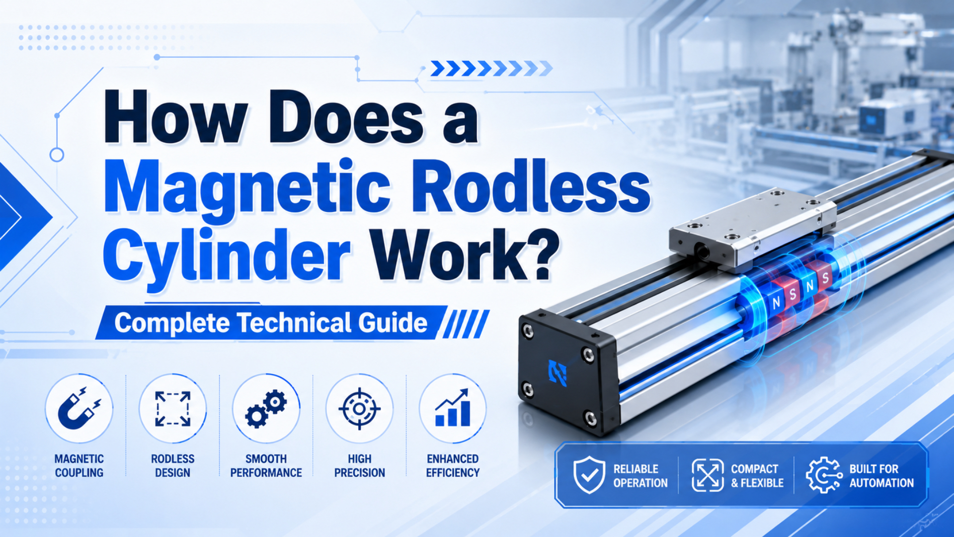
A magnetic rodless cylinder works by driving an internal piston with compressed air and using permanent magnets to pull an external carriage through a sealed non-magnetic tube. SMC lists CY3B magnetically coupled rodless cylinders in bore sizes from 6 to 63 mm, which shows how broad this compact actuator format has become (SMC, 2026).
The clean trick is that the carriage never penetrates the pressure tube. There is no external piston rod, no long rod extension, and no slot through the tube wall. The piston and carriage remain synchronized only as long as the magnetic coupling force is higher than the load, friction, acceleration force, and safety margin.
A magnetic rodless cylinder is a sealed pneumatic linear actuator where permanent magnets on the internal piston and external carriage transmit motion through the cylinder wall. It is useful when you need compact travel, clean exterior geometry, and moderate force, but it is not the right answer for every high-load or high-shock axis.
Key Takeaways
- SMC’s CY3B family spans 6-63 mm bores, so magnetic rodless cylinders cover small to mid-size pneumatic motion.
- NdFeB magnet remanence commonly drops about 0.12% per deg C, so temperature can reduce coupling margin.
- Size the actuator from magnetic holding force, payload, acceleration, air gap, orientation, and decoupling risk.
The mistake I see most often is treating magnetic coupling as invisible hardware. It is not. It is a force limit. Once you draw that limit on the sizing sheet, failures such as carriage slip, position drift, weak acceleration, and temperature sensitivity become easier to predict.
What Are the Core Components of a Magnetic Rodless Cylinder?
SMC’s CY3B-Z magnetically coupled rodless cylinder uses a double-acting format and bore sizes from 6 to 63 mm, while the product page notes that the newer design reduces mass by 16% on one 32 mm, 100 mm-stroke comparison (SMC, 2026). The core components are the tube, piston, magnets, carriage, seals, end caps, and mounting hardware.
The cylinder tube is the pressure boundary. It must be strong enough for working pressure and thin enough, in the magnetic region, to keep the internal and external magnet sets close. Aluminum is common because it is light and does not become a strong magnetic path that steals flux from the coupling.
The internal piston carries one magnet set and the piston seals. The external carriage carries the matching magnet set and the load interface. When compressed air pushes the internal piston, the magnetic field pulls the carriage with it.
End caps handle the air ports and cushion hardware. Mounting hardware keeps the cylinder aligned with the machine frame. If the external load creates a moment, the carriage or a separate guide must carry that moment. The cylinder tube should not be treated as a linear guide unless the catalog explicitly permits that load.
How Does Magnetic Coupling Transfer Force Through the Cylinder Wall?
Festo describes magnetically coupled cylinders as pneumatic rodless linear actuators whose slides are moved by a magnetic coupling with the piston (Festo, 2026). The force transfer is non-contact: internal and external magnet sets align across the closed tube and pull each other along the stroke.
When air enters one port, pressure acts on the piston area. The piston moves. The carriage follows because the external magnet pack is attracted to the internal magnet pack. If load force rises above the coupling force, the carriage can lag, slip, or decouple.
Think of coupling force as a clutch rating. It must exceed static load, acceleration load, friction, vertical load components, external process force, and the margin you choose for wear, temperature, and contamination. A stronger magnet set helps, but it does not fix poor load geometry.
The wall and air gap matter because magnetic field strength drops as separation increases. In a real cylinder, that separation includes tube wall thickness, clearances, coatings, wear, and any contamination stuck between the carriage and tube. Small mechanical changes can become real force losses.
From what we have seen, the first symptom of a marginal coupling is not dramatic failure. It is a carriage that hesitates on fast starts, lands inconsistently near the stop, or slips only when the machine is warm. That pattern usually points back to load margin, speed, or gap.
What Types of Magnets Are Used in Magnetic Rodless Cylinders?
Arnold Magnetic Technologies lists NdFeB grade N52 with a maximum energy product of 51 MGOe and a reversible induction temperature coefficient of -0.12% per deg C, while K&J Magnetics lists 176 deg F or 80 deg C as the maximum operating temperature for standard N-grade neodymium magnets (Arnold, 2026; K&J Magnetics, 2026).
Neodymium iron boron, usually written NdFeB, is the high-force choice for compact cylinders. It gives high magnetic output in a small package, which is why it is common where the cylinder bore and carriage size are limited.
Ferrite magnets cost less and tolerate temperature well, but they provide much lower magnetic energy density. They may be useful in cost-sensitive or low-force designs, but they usually require more magnet volume for the same coupling force.
Samarium cobalt magnets are chosen when temperature or chemical resistance matters more than cost. They are less common in commodity pneumatic cylinders, but they can make sense in hot or harsh environments where ordinary neodymium would lose too much margin.
Do not select magnet material by name alone. Ask for the magnet grade, maximum operating temperature, protective coating, and coupling-force data for the finished actuator, not just the raw magnet.
How Do Sealing Systems Work in Magnetic Rodless Cylinders?
Parker’s P1Z documentation describes the P1Z as a magnetically coupled rodless air cylinder, and the operating-instruction title identifies it as a rodless, magnetically coupled pneumatic cylinder (Parker P1Z catalog, 2025; Parker instructions, 2025). The sealing advantage is that the pressure tube can remain closed along the stroke.
In a mechanically coupled rodless cylinder, the carriage must connect through a slot, so the seal band becomes a major design feature. In a magnetic rodless cylinder, the carriage does not need a slot. The main dynamic seals are on the internal piston, closer to a conventional pneumatic cylinder.
That does not mean sealing is automatic. Piston seals still wear. End-cap seals still age. Port fittings can leak. Wipers or protective covers may still be needed outside the tube if dust, metal chips, or washdown water can enter the carriage path.
Clean or dusty environments are the real test. Magnetic coupling can remove the long external rod and slot, but the exposed carriage still needs protection. If steel particles stick to the carriage magnet area, the cylinder may become noisy, sticky, or weak.
What Factors Affect Magnetic Coupling Performance?
K&J Magnetics warns that standard N-grade neodymium magnets begin to lose strength if heated above 176 deg F or 80 deg C, and Arnold lists NdFeB reversible induction coefficient values around -0.12% per deg C for several grades (K&J Magnetics, 2026; Arnold, 2026). Temperature is only one coupling-risk factor.
Air gap is usually the first variable to check. A larger separation between magnet sets lowers available coupling force. The gap is affected by tube thickness, carriage clearance, wear, debris, coatings, and alignment.
Alignment is the second variable. Internal and external magnets need to stay centered through the stroke. Off-center loading bends brackets and guide hardware, which changes the gap and concentrates wear.
Speed and acceleration are the third variable. A carriage that holds at low speed can decouple during a fast start because acceleration force adds to the load. This is why pneumatic speed adjustments should be tested with the real payload, not an empty carriage.
External magnetic interference is less common, but it is not imaginary. Large motors, magnetic tooling, welding fixtures, ferrous dust, and nearby permanent magnets can disturb sensing or attract contamination. Keep the magnetic zone clean and documented.
How Do You Calculate Force and Performance Parameters?
NASA Glenn explains Pascal’s principle as pressure transmitted through a confined fluid, which is the basis for the pneumatic force calculation F = P x A before losses (NASA Glenn, 2021). In a magnetic rodless cylinder, the useful force is also capped by magnetic coupling force and the carriage load path.
Use two separate calculations. First, calculate pneumatic thrust from pressure and piston area. Second, check the manufacturer’s magnetic coupling or breakaway force. The lower value, after friction and margin, is the force you can safely design around.
Ideal pneumatic force = pressure x piston area

Design force available =
  min(pneumatic thrust, magnetic coupling force)
  - seal friction
  - guide friction
  - safety margin
For acceleration, use:
Acceleration force = moving mass x accelerationThen add gravity, process force, hose drag, carriage friction, and any stop impact. If the cylinder is vertical or angled, split the load into gravity and guide components. A magnetic rodless cylinder can be compact and clean, but it does not cancel the load path.
Festo’s DGO technical data, for example, lists breakaway force values for the magnetic coupling in pounds-force across different inch-series sizes (Festo DGO PDF, 2025). That is the kind of catalog value you need before final sizing.
What Are Common Problems and Solutions for Magnetic Rodless Cylinders?
SMC’s CY3B page lists optional low-speed and heat-resistant variants, including low-speed ranges of 10-50 mm/s and 5-50 mm/s and a heat-resistant option of -10 to 150 deg C (SMC, 2026). Those options exist because speed, temperature, and coupling margin change real behavior.
The most common problem is decoupling. The internal piston moves but the external carriage slips, lags, or stops. Causes include excessive load, aggressive acceleration, shock impact, high friction, added tooling weight, or reduced coupling from heat and gap change.
The second problem is position drift. If a station expects the carriage to hold a location under side load or vibration, the magnetic coupling may not be enough by itself. Use external stops, clamps, brakes, sensors, or a different actuator where the process needs a positive hold.
The third problem is contamination. Ferrous particles are especially awkward because the magnet area attracts them. Clean the carriage path and protect the cylinder from metal dust where possible. If the machine throws chips, grinding fines, or weld spatter, treat the environment as hostile.
The fourth problem is wrong expectation. Magnetic rodless cylinders are excellent for clean, compact, moderate-force travel. They are not a hidden replacement for a guided mechanical rodless actuator in every heavy moment-load application.
Maintenance and Troubleshooting Checklist
Parker notes in its rodless-cylinder catalog that temperature below freezing requires moisture-free air, and that reminder applies broadly to pneumatic actuator maintenance (Parker rodless catalog, 2025). Air quality, ferrous contamination, carriage alignment, and baseline cycle data usually decide service life over repeated production cycles.
Daily checks should look for air leaks, uneven motion, carriage hesitation, new scraping noise, damaged sensor cables, and foreign material on the cylinder tube. Do not wait for full decoupling before cleaning the carriage path.
Weekly or monthly checks should record supply pressure, speed settings, load changes, mounting-bolt condition, guide play, cushion behavior, and stop impact. A change in any of those can reduce coupling margin even when the cylinder itself is healthy.
A useful baseline test is simple: after commissioning, record payload mass, supply pressure, extend time, retract time, ambient temperature, and whether the carriage stays coupled through five fast cycles. That one record makes later troubleshooting much less speculative.
For RFQs, send:
- Bore or required force
- Stroke and cycle time
- Payload mass and center-of-gravity offset
- Horizontal, vertical, or angled mounting
- Required acceleration and stopping method
- Ambient temperature and duty cycle
- Dust, metal particle, washdown, or cleanroom exposure
- Position sensor and feedback needs
- Whether decoupling detection is required
- Whether a mechanical lock, brake, or external guide is required
The key is honesty about load and environment. A magnetic rodless cylinder that is perfect in a lab can be a poor fit beside metal chips, high shock, or a hanging vertical load.
FAQs About Magnetic Rodless Cylinders
Festo describes magnetically coupled cylinders as pneumatic rodless linear actuators moved by magnetic coupling with the piston, and SMC’s CY3B product page lists bore sizes from 6 to 63 mm (Festo, 2026; SMC, 2026). These answers focus on practical selection and failure prevention.
How does a magnetic rodless cylinder work internally?
Compressed air moves an internal piston inside a sealed non-magnetic tube. Magnets on that piston attract matching magnets in the external carriage, so the carriage follows the piston without a slot or physical rod. The carriage stays synchronized only while coupling force exceeds the load and dynamic forces.
What is the main advantage over a mechanically coupled rodless cylinder?
The main advantage is the closed pressure tube. Because the carriage is magnetically coupled, the cylinder does not need a longitudinal slot through the tube wall. That can help in clean or dusty environments, although the external carriage still needs protection from debris and impact.
What causes a magnetic rodless cylinder to decouple?
Decoupling happens when load, acceleration, friction, impact, or process force exceeds the magnetic coupling force. Heat, increased air gap, misalignment, and metal debris can lower the available margin. The fix is not always a larger cylinder; sometimes it is slower acceleration, better guiding, or a different actuator style.
Are neodymium magnets always the best choice?
No. Neodymium gives high energy density, but temperature and corrosion can be limiting factors. Arnold lists high energy products for NdFeB grades, while K&J notes standard N-grade neodymium maximum operating temperature at 80 deg C. Hot or chemically harsh applications may need another magnet family or special cylinder option.
Can magnetic rodless cylinders be used vertically?
Yes, but vertical use needs careful load and safety review. Gravity adds or subtracts from the pneumatic force depending on direction, and a decoupled carriage can move unexpectedly. Use load holding, external guidance, brakes, or another actuator if a falling load could damage equipment or injure someone.
What maintenance matters most?
Keep the air clean and dry, keep ferrous particles away from the magnetic carriage area, and track baseline cycle behavior. If speed, sound, temperature, or stopping consistency changes, inspect coupling margin, guide alignment, seal condition, and contamination before simply increasing pressure.
Final Selection Advice
AutomationDirect explains that rodless cylinders provide compact pneumatic linear motion by moving a load without the extra rod-extension space required by a traditional cylinder (AutomationDirect, 2020). A magnetic rodless cylinder adds one more benefit: a sealed tube with non-contact force transfer.
Choose this actuator when the job needs compact travel, moderate force, clean exterior geometry, and limited side loading. Be cautious when the job needs high shock resistance, high moment capacity, exact intermediate positioning, or positive load holding after air loss.
The best selection sentence is specific: “We need this stroke, this payload, this acceleration, this temperature range, this contamination protection, and this coupling margin.” If you can say that, the magnetic rodless cylinder stops being mysterious and becomes a normal engineering choice.
Related internal resources: rodless cylinder selection, pneumatic cylinder basics, basic pneumatic laws, pneumatic valves, and engineering RFQ support.
Sources
- SMC, “Magnetically Coupled Rodless Cylinder/Basic Type CY3B”. https://test.smcworld.com/webcatalog/ja-jp/air-cylinders/magnetically-coupled-rodless-cylinders/CY3B
- Festo, “Magnetically coupled cylinders”. https://www.festo.com/us/en/c/products/actuators-and-drives/pneumatic-cylinders/rodless-cylinders/magnetically-coupled-cylinders-id_pim385/
- Festo, “Rodless cylinders DGO - Inch Series” PDF. https://www.festo.com/media/catalog/204205_documentation.pdf
- Parker Hannifin, “P1Z Series Magnetically Coupled Rodless Air Cylinders”. https://www.parker.com/content/dam/Parker-com/Literature/Literature-Files/pneumatic/serv/P1Z.pdf
- Parker Hannifin, “P1Z series operating instructions”. https://www.parker.com/content/dam/Parker-com/Literature/Pneumatics-Division-Europe/PDE-Documents/Cylinders/Parker_Pneumatic_P1Z_Operating_Instructions_P-A7P020GB.pdf
- Parker Hannifin, “Rodless Pneumatic Cylinders Catalog 0961”. https://www.parker.com/content/dam/Parker-com/Literature/Literature-Files/pneumatic/Literature/Actuator-Cylinder/0961_Parker-Rodless-Cylinder-Catalog.pdf
- Arnold Magnetic Technologies, “Neodymium Magnets (NdFeB)”. https://www.arnoldmagnetics.com/products/neodymium-iron-boron-magnets/
- K&J Magnetics, “Neodymium Magnet Info”. https://www.kjmagnetics.com/neodymium-magnet-info.asp
- NASA Glenn Research Center, “Pascal’s Principle”. https://www.grc.nasa.gov/www/k-12/WindTunnel/Activities/Pascals_principle.html
- AutomationDirect, “Rodless Cylinders Provide a Compact Pneumatic Linear Motion Option”. https://library.automationdirect.com/rodless-cylinders-provide-compact-pneumatic-linear-motion/