

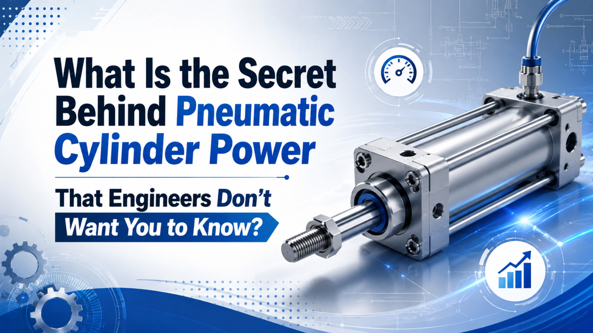
Pneumatic cylinder power is not a hidden trick. It is pressure acting on piston area, then losing some of that ideal output through rod area, friction, leakage, pressure drop, valve flow, tubing limits, and load alignment. The practical question is simple: how much useful force reaches the machine?
That wording matters because “power” gets used loosely in cylinder conversations. Some teams mean thrust force. Some mean cycle speed. Some mean total compressed-air energy. A good RFQ separates all three: force, speed, and air consumption.
Key Takeaways
- Cylinder force starts with
F = P x A, and NIST lists 1 psi as 6,894.757 Pa.- ISO 15552 covers standard pneumatic cylinders up to 10 bar, so pressure margin is finite.
- CAGI’s 10% pressure-drop rule and DOE’s 20-30% leak warning explain why real machines lose power before air reaches the piston.
The useful “secret” is that a powerful cylinder is usually a powerful air path. Bore size matters, but the valve, tubing, regulator, muffler, fittings, rod load, and leakage decide whether the calculated force shows up at the workpiece.
What Does Pneumatic Cylinder Power Really Mean?
Pneumatic cylinder power usually means available thrust, but true mechanical power is force times velocity. ISO 15552 sets a 10 bar maximum rated pressure scope for standard detachable-mounting cylinders, while NASA’s pressure-area relation explains why bore size converts that pressure into force (ISO 15552, 2018; NASA Glenn, 2021).
A cylinder can feel “strong” in three different ways:
- It produces enough force to overcome the load.
- It moves fast enough for the cycle time.
- It repeats the stroke without leaks, drift, or shock.
Those are different checks. A larger bore increases force but also increases chamber volume, which may slow the stroke if valve and tubing flow stay the same. Higher pressure increases force, but it also raises air use and can make leaks more expensive.
Use this quick separation before sizing:
Force = pressure x effective piston area
Speed = air flow / effective piston area
Air use = chamber volume x absolute-pressure ratio
If the machine is weak, don’t change the cylinder first. Measure pressure at the cylinder port during motion. A regulator gauge upstream can look healthy while the cylinder sees a lower dynamic pressure.
How Does Pascal’s Law Turn Air Pressure Into Force?
Pascal’s principle says pressure in a confined fluid is transmitted through the fluid, and NASA gives the relationship as F1 / A1 = F2 / A2. For pneumatic sizing, the same pressure-area logic becomes F = P x A, so a larger piston area produces more force at the same pressure (NASA Glenn, 2021).
In a pneumatic cylinder, compressed air enters one chamber and pushes against the piston face. The opposite chamber must exhaust. If the exhaust path is blocked, the piston fights back pressure and the useful force drops.
NIST lists 1 psi as 6,894.757 Pa, so a 100 psi supply is about 689,476 Pa before pressure drop (NIST, 2025). That makes the unit conversion straightforward:
1 psi = 6,894.757 Pa
1 bar = 100,000 Pa
6 bar = 600,000 Pa
For a 63 mm bore at 6 bar:
Area = pi x (0.063 m)^2 / 4 = 0.003117 m2
Ideal extend force = 600,000 Pa x 0.003117 m2 = 1,870 N
That is ideal force at the piston face. The machine will see less after seal friction, guide friction, rod alignment, pressure drop, and load geometry. Put another way, the formula gives the ceiling. The installation decides how close you get.
How Do Bore, Stroke, and Rod Area Change Output?
Bore sets piston area, stroke sets swept volume, and rod diameter reduces retract-side area. ISO 15552 covers interchangeable cylinders with 32 mm to 320 mm bores and a 10 bar pressure series, so those dimensions are the normal starting point for many industrial RFQs (ISO 15552, 2018).
Extend force uses the full piston area on a single-rod cylinder. Retract force uses piston area minus rod area because the rod occupies part of the chamber. That is why retract force is usually lower than extend force.
Use these equations:
Piston area = pi x bore^2 / 4
Rod area = pi x rod diameter^2 / 4
Extend force = pressure x piston area
Retract force = pressure x (piston area - rod area)
At 6 bar, a 63 mm bore with a 20 mm rod calculates like this:
| Item | Calculation | Result |
|---|---|---|
| Piston area | pi x 63^2 / 4 | 3,117 mm2 |
| Rod area | pi x 20^2 / 4 | 314 mm2 |
| Extend force at 6 bar | 600,000 Pa x piston area | 1,870 N |
| Retract force at 6 bar | 600,000 Pa x net rod-side area | 1,682 N |
Stroke does not directly change force, but it changes buckling risk, guide load, air use, fill time, and mounting stress. Long strokes need more attention to rod support and alignment. If side load is present, add external guides instead of asking the rod to act like a slide rail.
How Do Flow and Pressure Drop Control Speed?
Cylinder speed depends on air flow through the whole path, not just the regulator setting. CAGI says well-designed compressed-air systems should have no more than 10% pressure drop from compressor discharge to point of use, and pressure drop comes from piping, fittings, filters, dryers, and components (CAGI, 2026).
Pressure creates force. Flow creates speed. That split helps troubleshooting because a cylinder can have enough static pressure but still move slowly if the flow path is restricted.
Common restrictions include:
- Undersized directional valves
- Long or narrow tubing
- Small push-in fittings
- Dirty filters
- Clogged exhaust mufflers
- Over-tightened flow controls
- Quick exhaust valves installed in the wrong place
The first check is dynamic pressure at the cylinder port during the stroke. If the gauge drops only when the cylinder moves, the air path is restricting flow. If the pressure stays high but the rod barely moves, look for side load, mechanical binding, internal leakage, or a load estimate error.
From replacement requests, the most misleading symptom is “normal pressure.” Many teams read the FRL gauge while the cylinder is idle. The useful measurement is pressure at the cap or rod port while the cylinder is moving under load.
Single-Acting vs Double-Acting Power
Single-acting cylinders use one pressurized port and a spring or gravity return, while double-acting cylinders use separate ports for extend and retract. AutomationDirect describes single-acting units as having one port and double-acting units as having separate ports for both directions (AutomationDirect, 2026).
Single-acting cylinders can reduce air use because only one direction is powered. The tradeoff is lower control over the return stroke and reduced working force when an internal spring opposes extension.
Double-acting cylinders use air in both directions. They are better when the retract stroke must pull a load, control speed, or hold position against a process force. They also make cycle behavior easier to tune because each direction has its own air path.
| Feature | Single-acting cylinder | Double-acting cylinder |
|---|---|---|
| Ports | Usually 1 | Usually 2 |
| Powered direction | One direction | Extend and retract |
| Return method | Spring, gravity, or load | Compressed air |
| Air use | Lower for simple strokes | Higher per full cycle |
| Best fit | Clamp, eject, simple push | Transfer, pull, controlled return |
If safety matters, define the lost-air position. A spring-return cylinder can fail toward a predictable state. A double-acting cylinder needs valve selection and risk review to decide what happens when air or power is lost.
How Much Air Does a Pneumatic Cylinder Use?
Air use depends on chamber volume and absolute pressure, not only bore. At 6 bar gauge, a cylinder chamber fills at roughly 7 bar absolute, so a 63 mm bore, 500 mm stroke cylinder uses about 10.9 liters of free air on extension before losses by calculated volume ratio (NIST, 2025).
The calculation starts with swept volume:
Chamber volume = area x stroke
Free-air use per stroke = chamber volume x absolute pressure / atmospheric pressure
For a 63 mm bore, 20 mm rod, 500 mm stroke, 6 bar gauge example:
| Stroke side | Chamber volume | Pressure multiplier | Free air used |
|---|---|---|---|
| Extend side | 1.56 L | 7x | 10.9 L |
| Retract side | 1.40 L | 7x | 9.8 L |
| Full double-acting cycle | 2.96 L | 7x | 20.7 L |
This is still a simplified estimate. Real systems add dead volume in tubing and valves, pressure drop, leakage, and exhaust losses. Long tubing can add surprising air use because the tube refills every cycle.
What Losses Make Real Cylinder Power Lower?
Real cylinder power drops when leakage, pressure drop, friction, and side load consume the margin between calculated force and required load. DOE says poorly maintained compressed-air systems can lose 20-30% of air capacity and power to leaks, while well-maintained systems should stay below 5-10% (DOE Sourcebook, 2016).
Four losses show up most often:
- Pressure loss before the cylinder
- Exhaust back pressure
- Internal leakage across the piston seal
- Mechanical friction from side load or misalignment
CAGI warns that raising compressor discharge pressure is a costly first response to point-of-use pressure problems; it recommends reducing restrictions instead (CAGI, 2026). That matters because increasing plant pressure can hide the real defect while increasing energy use everywhere.
Use this diagnostic order:
| Symptom | First measurement | Likely issue |
|---|---|---|
| Weak only during motion | Pressure at cylinder port | Flow restriction or pressure drop |
| Weak at all times | Regulated pressure and load | Undersized bore or low supply |
| Moves slowly both ways | Valve, tubing, muffler flow | Exhaust or supply restriction |
| Drifts under load | Isolated chamber pressure | Piston seal or valve leakage |
| Slams at end | Cushion and flow control setting | Excess flow or no deceleration |
A bigger cylinder is not always the fix. If the root problem is pressure drop, a larger bore may consume more air and make the pressure sag worse. Fix the air path first, then resize.
Where Do Seals, Guides, and Valves Affect Power?
Seals, guides, and valves decide how much calculated force becomes usable force. ISO 8573-1 defines compressed-air purity classes for particles, water, and oil, and AutomationDirect notes that cylinders rely on air entering one side while the opposite side exhausts (ISO 8573-1, 2010; AutomationDirect, 2026).
Seals affect power in two ways. A tight seal preserves pressure but adds friction. A worn seal reduces friction for the wrong reason: it leaks. Both cases can create confusing symptoms if you only watch rod motion.
Guides affect power because a cylinder rod is not a precision linear bearing. Side load bends the rod, increases friction at the bushing, damages seals, and can make a correctly sized cylinder look weak. For pushing guided loads, let the guide carry side load and let the cylinder provide force.
Valves affect power because they set both supply and exhaust capacity. A valve that is too small can starve the extend stroke. A clogged muffler can choke exhaust and create back pressure. Flow controls should tune speed, not compensate for undersized plumbing.
For air preparation, specify the purity level where the actuator needs it. ISO 8573-1 covers particles, water, and oil independently of the location in the compressed-air system (ISO 8573-1, 2010). That location clause matters. Air can be clean after the dryer but contaminated at the cylinder if the distribution line is wet or dirty.
Useful related parts include an FRL unit, a correctly sized solenoid valve, and the right ISO 15552 pneumatic cylinder for the load and mounting.
Troubleshooting Weak or Slow Cylinder Power
Troubleshooting should start with measured pressure, measured timing, and the load path. DOE gives leak formulas using compressor load and unload time, and CAGI recommends 20 feet per second or lower air velocity through piping to reduce turbulence and pressure drop (DOE Sourcebook, 2016; CAGI, 2026).
Use this field sequence:
- Confirm supply pressure at the FRL while the cylinder moves.
- Measure pressure at the cylinder cap and rod ports during the stroke.
- Check exhaust mufflers, flow controls, and quick exhaust valves.
- Isolate the cylinder and listen for internal leakage.
- Disconnect the load if safe and test free motion.
- Inspect rod alignment, clevis angle, guides, and stops.
- Compare the measured cycle time against the required flow.
If the cylinder is weak only near the end of stroke, check mechanical binding or cushion settings. If it is weak throughout the stroke, check pressure and bore sizing. If it is fast unloaded but weak loaded, the load estimate or side-load condition is probably wrong.
For a replacement RFQ, send more than the old part number. Include bore, stroke, rod diameter, mounting style, port size, working pressure, load, target cycle time, environment, sensor needs, and photos of the installed load path. That turns a vague “more power” request into an engineering selection.
For a step-by-step motion explanation, use the companion article on how a pneumatic cylinder works in automation. This article stays focused on force, air use, and loss control so the two pages do not compete for the same query.
Conclusion
Pneumatic cylinder power starts with F = P x A, but the useful output depends on the whole compressed-air path. ISO 15552 gives a 10 bar standard-cylinder scope, CAGI recommends no more than 10% pressure drop, and DOE warns that poor leak control can waste 20-30% of air capacity and power (ISO 15552, 2018; CAGI, 2026; DOE Sourcebook, 2016).
Start with force math. Then check flow, leakage, pressure drop, side load, valve sizing, tubing, exhaust, and air quality. If those are healthy, bore and pressure changes are easier to justify. If they are not healthy, a larger cylinder may only make the air problem louder.
FAQs About Pneumatic Cylinder Power
FAQ answers should separate force, speed, and energy because those three ideas often get called “power.” NASA’s pressure-area relation explains force, CAGI’s 10% pressure-drop target explains many speed complaints, and DOE’s 20-30% leak warning explains wasted compressed-air capacity (NASA Glenn, 2021; CAGI, 2026; DOE Sourcebook, 2016).
What formula calculates pneumatic cylinder force?
Use F = P x A, where F is force, P is working pressure, and A is effective piston area. For retract force on a single-rod double-acting cylinder, subtract rod area from piston area before multiplying by pressure.
Why is retract force lower than extend force?
Retract force is lower because the piston rod occupies part of the rod-side chamber. The effective retract area is piston area minus rod area. With the same pressure, less area means less force, even though the supply pressure has not changed.
Does higher pressure always make a cylinder more powerful?
Higher pressure increases ideal force, but it is not always the right fix. If the cylinder is weak because of leaks, small tubing, restricted mufflers, dirty filters, or bad alignment, raising pressure may increase air cost while leaving the root problem in place.
Why does a cylinder move slowly even with enough pressure?
Pressure creates force, but flow controls speed. A cylinder can have enough pressure and still move slowly when the valve, tubing, fittings, filter, flow control, or exhaust muffler restricts air movement. Measure pressure at the cylinder port during motion.
How do I estimate pneumatic cylinder air consumption?
Calculate chamber volume from area times stroke, then multiply by the absolute pressure ratio. At 6 bar gauge, the chamber fills at roughly 7 bar absolute. A double-acting cycle uses both the cap-end and rod-end chamber volumes.
What should I send for a higher-power cylinder replacement?
Send bore, stroke, rod diameter, mounting style, port size, pressure, load, cycle time, environment, sensor requirements, old model code, and installation photos. Also describe whether the cylinder is weak, slow, leaking, drifting, slamming, or sticking.
Sources
- ISO: ISO 15552:2018, pneumatic cylinder dimensions, detachable mountings, 10 bar maximum rated pressure, and 32-320 mm bore scope. Retrieved 2026-06-03.
- ISO: ISO 8573-1:2010, compressed-air purity classes for particles, water, and oil. Retrieved 2026-06-03.
- NASA Glenn: Pascal’s Principle and Hydraulics, pressure transmission and piston force-area relationship. Retrieved 2026-06-03.
- NIST: Pressure and Gas Flow Unit Conversions, psi, pascal, atmosphere, and gas-flow conversion references. Retrieved 2026-06-03.
- DOE: Improving Compressed Air System Performance, Third Edition, leak loss ranges and compressed-air troubleshooting methods. Retrieved 2026-06-03.
- CAGI: Technical Brief on Pressure Drop, 10% pressure-drop target and piping velocity guidance. Retrieved 2026-06-03.
- AutomationDirect: What is a Pneumatic Cylinder?, video explainer for bore, stroke, ports, piston, rod, and cylinder operation. Retrieved 2026-06-03.
- AutomationDirect: Pneumatic Air Cylinders, single-acting and double-acting cylinder overview. Retrieved 2026-06-03.