

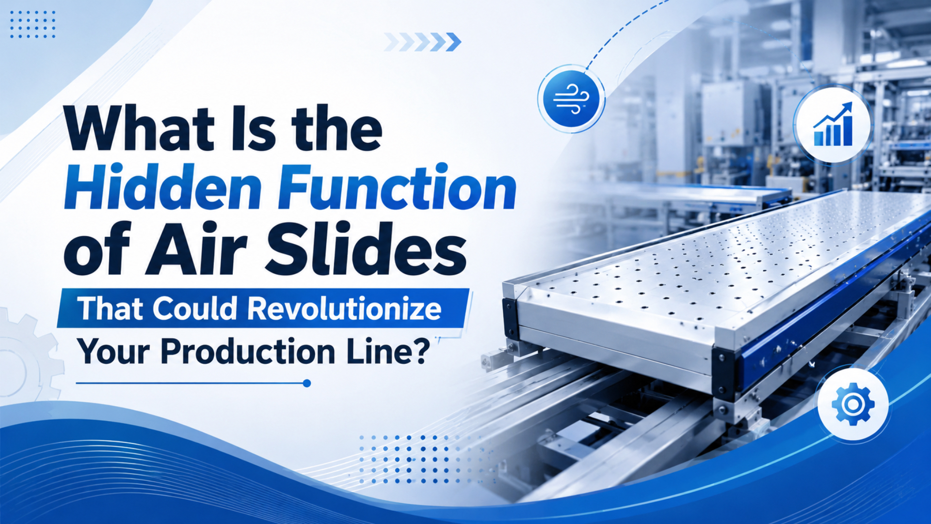
An air slide’s hidden function is not just moving a carriage from left to right. It packages compressed-air force, integrated guidance, and a compact load platform into one linear-motion unit. DOE data matters here because compressed air accounts for 10% of electricity and 16% of motor-system energy use in U.S. manufacturing (U.S. DOE, 2000).
That means an air slide should not be selected only because it looks compact. It should earn its place by solving a specific machine problem: a long stroke with no rod overhang, a guided payload, a clean work envelope, or a simple two-position motion that does not justify an electric axis.
The function of an air slide is to convert compressed air into guided linear motion while carrying side loads and moments that a bare pneumatic cylinder rod should not be asked to handle. In plain shop-floor terms, it moves the tooling and supports the tooling at the same time.
Key Takeaways
- DOE reports compressed air uses 10% of U.S. manufacturing electricity, so air-slide selection should include energy and leakage checks.
- The real value is guided motion in a short footprint, not vague “automation improvement.”
- Size by load, moment, speed, mounting orientation, and air quality.
The useful way to think about an air slide is this: it is not a cylinder with a nicer carriage. It is a small linear-motion module powered by air. That framing forces you to check guide load, moment, alignment, air consumption, and stop control before the machine is built.
What Is the Primary Function of an Air Slide?
The primary function is guided linear motion, and the energy source is worth noticing: DOE reports compressed air systems use 10% of all electricity and roughly 16% of motor-system energy in U.S. manufacturing (U.S. DOE, 2000). An air slide is best when that air delivers compact, simple motion.
At the actuator level, an air slide uses pressure on a piston area to create force. At the machine level, the guide carriage keeps the load aligned while the piston moves. Those are two different jobs. If you ignore the second one, the slide may move, but the guides, seals, and mounting bolts pay the price.
The word “hidden” in the title is really about support. A basic cylinder produces push or pull force. An air slide adds a guided platform that resists side load and moment. That is why these units show up in pick-and-place stops, pusher stations, small transfer nests, labeling heads, glue heads, test fixtures, and guarded product-handling stations.
So the question is not “Can an air slide move this part?” The better question is “Does a guided pneumatic slide give enough accuracy, support, speed, cleanliness, and energy discipline for this station?” That is where good selection starts.
How Do Air Slides Provide Linear Motion Without Exposed Rods?
AutomationDirect describes rodless cylinders as using an internal piston connected to an external carriage that moves alongside the cylinder body, letting the actuator fit into tighter spaces than a rodded cylinder (AutomationDirect, 2020). An air slide uses the same practical idea: move the load without sending a rod beyond the machine frame.
There are several ways to transfer force from the piston to the carriage. Mechanically jointed rodless cylinders use a slot and sealing band. Magnetically coupled designs use magnets through a nonmagnetic tube. Guided slide cylinders use a compact cylinder body tied to a bearing-supported table.
The machine benefit is footprint. A traditional rodded cylinder needs room for the body and the extended rod. A rodless slide keeps the useful travel close to the actuator body. That can help when a glue head, labeler, stopper, or inspection probe must travel across a short machine opening.
In our experience, the best air-slide applications are rarely the ones with the most impressive speed claim. They are the stations where a normal cylinder creates a packaging, guarding, or alignment problem. Remove the rod overhang, and the whole machine layout gets calmer.
What Components Make an Air Slide Work?
SMC’s MY1B mechanically jointed rodless cylinder page lists bore sizes of 25, 32, and 40 mm and says its new version improves load mass and allowable moment by up to 30% compared with the prior MY1B (SMC, 2026). That tells you which components matter most: piston, carriage, guide, and moment capacity.
The cylinder body contains the pressure chambers. The piston converts air pressure into force. The carriage gives the user a load-mounting surface. The guides keep the carriage from twisting, pitching, or binding when the payload is not perfectly centered.
For small guided slides, the guide may be built into a compact table. For long rodless actuators, the load may ride on an external carriage with separate guide rails. Do not treat those as equivalent without checking moment ratings. A long arm mounted off-center can overload a neat-looking slide quickly.
The controls are ordinary pneumatic controls: directional valve, flow controls, regulator, sensors, cushioning, and sometimes shock absorbers or hard stops. The air slide is only one part of the motion system. Bad air quality or undersized valves can make a good slide look bad.
When reviewing a drawing, mark four dimensions before approving the slide: stroke, carriage length, payload center of gravity, and distance from the mounting face. Those four numbers often reveal the problem before a catalog table does.
How Should You Size Loads and Orientations?
SMC rodless-cylinder selection data uses load factor checks for static load and dynamic moment, and warns that when the total guide load factor exceeds 1, the designer should reduce speed, increase bore size, or revise the guide arrangement (SMC catalog PDF, 2024). That is the heart of air-slide sizing.
Start with force. For a pneumatic actuator, ideal force is pressure times piston area. Then subtract friction, pressure drop, back pressure, and any gravity component. If the slide moves upward, gravity fights the motion. If it moves downward, gravity may help the motion but hurt stopping.
Next, check guide load and moment. A payload mounted directly over the carriage is friendly. A payload hanging 150 mm from the carriage face is not. Even a light part can create a large moment if the tooling sticks out far enough.
Use this sizing sequence:
| Check | Why it matters | What to send in the RFQ |
|---|---|---|
| Stroke and cycle time | Sets bore, valve size, and cushioning demand | Stroke, extend time, retract time |
| Payload mass | Sets force and guide load | Part mass plus gripper or fixture mass |
| Center of gravity | Sets moment on the carriage | X, Y, and Z offset from mounting face |
| Mounting orientation | Changes gravity and guide loading | Horizontal, vertical, inverted, or angled |
| Stop method | Controls impact and repeatability | Cushioning, shock absorber, hard stop, sensor stop |
Do not size only from catalog thrust. A slide can have enough thrust and still fail because the moment is wrong. That failure mode is easy to miss because the first test cycles may look fine.
Where Do Air Slides Fit in Clean or Compact Machines?
ISO 14644-1:2015 classifies cleanroom air by airborne-particle concentration for particle sizes from 0.1 micrometer to 5 micrometers, and ISO says the 2015 edition remains current after 2021 confirmation (ISO, 2026). Air slides fit clean machines when the actuator layout reduces exposed moving surfaces and keeps particle traps manageable.
Clean does not mean magic. A sealed or compact slide can reduce exposed rods, grease points, and awkward guard openings, but it still needs compatible materials, cleaning access, and correct air exhaust handling. If the air exhaust blows toward an open product, the actuator choice may solve one problem while creating another.
For washdown or dusty areas, IP ratings can help frame the conversation. IEC explains that IP ratings classify how well enclosures resist solid-particle and water ingress (IEC, 2026). An IP code on a sensor or accessory does not automatically make the entire slide assembly washdown-ready.
Air slides often work well in compact packaging, food handling, electronics assembly, lab automation, and small inspection stations. The common thread is not the industry. It is the need for a short, guided motion with limited machine space and moderate force.
What Control Functions Matter on an Air Slide?
ODVA describes EtherNet/IP as an industrial network technology for automation communication, while AutomationDirect’s linear-slide material points users toward setup and support resources for slide assemblies (ODVA, 2026; AutomationDirect, 2026). The air slide itself may be pneumatic, but its control quality depends on valves, sensors, and machine sequencing.
For simple two-position motion, limit sensors and flow controls may be enough. For intermediate stops or measured positions, you need feedback hardware and a controller strategy that fits pneumatic compressibility. Air is springy. It does not behave like a ball screw servo.
Speed control is usually handled with meter-out flow control, cushioning, and sometimes shock absorbers. Be careful with fast light-load testing. The real payload may hit the end stop harder, especially if the center of gravity is far from the guide.
Force control comes from pressure regulation, but pressure control is not precision force feedback. If the process needs exact pressing force, delicate insertion, or measured displacement under load, compare the pneumatic slide with an electric actuator before committing.
What Safety Limits Should Buyers Check?
OSHA 29 CFR 1910.212 requires machine guarding to protect operators and other employees from hazards such as point of operation, nip points, rotating parts, flying chips, and sparks (OSHA, 2026). An air slide can be part of a guarded station, but it is not a guard by itself.
Check what happens when air pressure is lost. A horizontal slide may coast, drift, or stop against friction. A vertical slide can drop if the load is not counterbalanced, locked, or otherwise controlled. If the load can injure someone, the safety function needs a documented risk assessment.
Check what happens when air returns. Restart can be just as hazardous as shutdown if the valve state, carriage position, and operator access are not controlled. Use sensors and reset logic where the risk assessment calls for them.
Finally, check noise and exhaust. Rapid pneumatic motion can create exhaust noise and particle movement. In clean or operator-close stations, add mufflers, exhaust routing, speed limits, and maintenance access to the design review.
Air Slides Compared With Other Linear Actuators
DOE found more than 50% of industrial compressed-air systems have opportunities for large energy savings with low project costs, and small to medium facilities averaged projected savings of 15% of compressed-air usage in DOE-related audits (U.S. DOE, 2000). That is why air slides should be compared, not assumed.
Against a rodded cylinder, the air slide usually wins on footprint and guided load support. The rodded cylinder usually wins on low cost and simplicity when the load is already guided elsewhere.
Against an electric actuator, the air slide can win on purchase price, speed for end-to-end moves, and tolerance of wet or dirty environments. The electric actuator usually wins on position control, repeatability, energy use, and programmable motion.
Against hydraulics, the air slide wins on cleanliness and simpler service. Hydraulics win when the force requirement is high and compact power density matters more than clean operation.
| Option | Best fit | Main warning |
|---|---|---|
| Air slide | Compact guided motion, moderate force, simple positions | Plant air cost and limited precision |
| Rodded cylinder | Low-cost push or pull with external guide | Rod overhang and side-load sensitivity |
| Electric actuator | Programmable positioning and energy control | Higher purchase cost and environmental limits |
| Hydraulic actuator | High force in compact space | Oil leaks, cleanliness, and maintenance burden |
The best choice is the one that removes the machine constraint without creating a bigger maintenance problem. A cheap actuator in the wrong place is expensive later.
Maintenance and RFQ Checklist
Parker’s rodless pneumatic catalog lists operating pressure up to 150 psig for OSP-P units and notes that temperatures below freezing require moisture-free air for pneumatic operation (Parker, 2025). Maintenance starts with air quality because water, dirt, and wrong lubrication shorten pneumatic-slide life.
Daily checks should catch air leaks, sticky motion, loose tooling, damaged cables, broken sensor brackets, and unusual exhaust noise. Weekly or monthly checks should review filter drains, regulator pressure, guide lubrication if required, cushion settings, and mounting bolts.
A useful acceptance test is simple: record the slide’s cycle time, supply pressure, payload mass, and stopping behavior on the first production day. Keep that baseline. When the same station later feels slow or noisy, you can compare evidence instead of guessing.
For RFQs, send more than bore and stroke. Include:
- Stroke, cycle rate, and expected duty cycle
- Payload mass and center-of-gravity offset
- Mounting orientation and available footprint
- Required end-position or mid-position accuracy
- Air pressure range and air preparation details
- Environment: dust, washdown, cleanroom, heat, chemicals
- Sensor, valve, and PLC interface needs
- Stop method: cushion, shock absorber, hard stop, or controlled deceleration
- Safety requirement if people can reach the motion zone
This is where buyers often save the most time. A supplier can help with a messy application if the load geometry is clear. A perfect part number with missing load data is still a gamble.
FAQs About Air Slide Functions
AutomationDirect says rodless cylinders use an internal piston with an external carriage and can fit into tighter spaces than traditional rodded cylinders (AutomationDirect, 2020). These FAQ answers focus on practical function, selection limits, and the checks engineers should make before buying.
What is the main function of an air slide?
An air slide provides guided linear motion from compressed air. It moves a carriage while supporting the attached payload through built-in or paired guides. That makes it useful when a basic cylinder needs extra guidance, compact packaging, or better control of side load and moment.
How is an air slide different from a rodless cylinder?
The terms overlap in everyday use. A rodless cylinder focuses on eliminating the external piston rod, while an air slide usually emphasizes a guided carriage or table. Some products are both: a rodless pneumatic actuator with an external guided carriage for carrying the load.
Are air slides accurate enough for precision assembly?
They can be repeatable enough for stops, transfers, clamps, and simple placement tasks, but air compressibility limits fine positioning. If the process needs programmable positions, measured force, or tight servo-style motion, compare the pneumatic slide with an electric actuator before choosing.
Can an air slide be used vertically?
Yes, but vertical use needs gravity, load holding, speed, and safety checks. The designer must confirm force margin in the lifting direction and safe behavior during air loss. Heavy vertical loads may need locks, counterbalance, controlled exhaust, or a different actuator.
What air quality does an air slide need?
Use clean, dry air that matches the manufacturer’s instructions. Moisture, debris, and wrong lubrication can damage seals, guides, and valves. Parker notes that below-freezing ambient temperatures require moisture-free air for pneumatic rodless cylinder operation, which is a good reminder for cold plants.
What should I send to get the right air-slide quote?
Send stroke, cycle time, payload mass, center-of-gravity offsets, mounting orientation, air pressure range, environment, sensor needs, and the required stop method. If the slide is near operators or can drop a load, include the safety requirement instead of leaving it implicit.
Final Selection Advice
SMC’s MY1B page highlights load-mass and allowable-moment improvements up to 30% on one rodless family, while DOE data shows compressed air is a major plant utility in manufacturing (SMC, 2026; U.S. DOE, 2000). That combination captures the real decision: mechanics and energy both matter.
Choose an air slide when compact guided motion solves a machine constraint better than a rodded cylinder, electric actuator, or hydraulic unit. Avoid it when the station needs high precision, high continuous duty, very high force, or low energy use above all else.
The strongest air-slide applications have a specific sentence behind them: “We need this stroke, this payload, this moment capacity, this cleanliness level, and this footprint.” Once you can say that, the selection stops being a catalog hunt and becomes an engineering decision.
Related internal resources: pneumatic cylinder basics, basic pneumatic laws, rodless cylinder selection, pneumatic valves, air preparation units, and engineering RFQ support.
Sources
- U.S. Department of Energy, “Assessment of the Market for Compressed Air Efficiency Services”, 2000. https://bptraining.ornl.gov/wp-content/uploads/2022/09/Compressed-air-sourcebook-by-DOE_3rd-Edition.pdf
- ISO, “ISO 14644-1:2015 Cleanrooms and associated controlled environments - Part 1: Classification of air cleanliness by particle concentration”, current after 2021 confirmation. https://www.iso.org/standard/53394.html
- IEC, “IP ratings”. https://www.iec.ch/ip-ratings
- SMC, “Mechanically Jointed Rodless Cylinder/Basic Type MY1B”. https://www.smcworld.com/webcatalog/en-sg/air-cylinders/mechanically-jointed-rodless-cylinders/MY1B-Z1-E
- SMC, “MY1B-Z mechanically jointed rodless cylinder catalog PDF”. https://www.smcworld.com/catalog/BEST-5-2-en/pdf/2-p1170-1186-my1b-z_en.pdf
- AutomationDirect, “Rodless Cylinders Provide a Compact Pneumatic Linear Motion Option”, 2020. https://library.automationdirect.com/rodless-cylinders-provide-compact-pneumatic-linear-motion/
- AutomationDirect, “Linear Slide Value Series Quick Start from AutomationDirect”, 2026. https://www.youtube.com/watch?v=9UlanmdpALU
- ODVA, “EtherNet/IP”. https://www.odva.org/technology-standards/key-technologies/ethernet-ip/
- OSHA, “29 CFR 1910.212 - General requirements for all machines”. https://www.osha.gov/laws-regs/regulations/standardnumber/1910/1910.212
- Parker Hannifin, “Rodless Pneumatic Cylinders Catalog 0961”. https://www.parker.com/content/dam/Parker-com/Literature/Literature-Files/pneumatic/Literature/Actuator-Cylinder/0961_Parker-Rodless-Cylinder-Catalog.pdf