

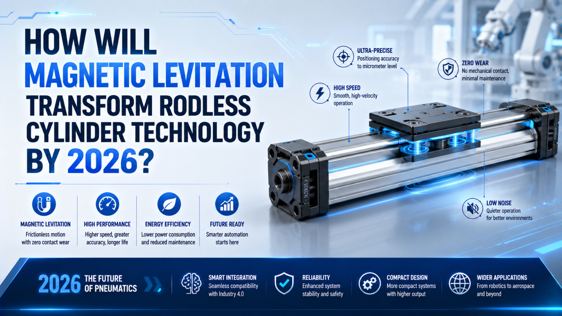
Magnetic levitation has not turned ordinary rodless pneumatic cylinders into seal-free, regenerative, micron-positioning actuators by 2026. Actual change is happening beside pneumatics: electric planar transport systems now levitate workpiece carriers, while magnetically coupled rodless cylinders remain compressed-air actuators with physical piston seals. That distinction matters. Magnetic coupling transfers force through a closed tube wall. Magnetic levitation suspends and controls a mover using electromagnetic forces. Shared magnets do not give the technologies the same pressure boundary, drive architecture, positioning capability, failure modes, or energy path.
Key Takeaways
- Magnetic coupling transfers force through a closed tube; it does not levitate the piston or remove its seals.
- Commercial planar systems publish levitation heights from 0.5 to 6 mm and micron-scale positioning data.
- Compare pneumatic, servo-pneumatic, electric linear, and planar maglev axes by the installed task, not by the word “magnetic.”
What Does “Magnetic Levitation Rodless Cylinder” Mean in 2026?
By July 2026, B&R publishes ACOPOS 6D levitation heights of 0.5 to 6 mm, while SMC still categorizes CY3 products as double-acting, magnetically coupled pneumatic cylinders (B&R, 2026; SMC, 2026). This phrase covers two distinct actuator classes, so engineers must identify the energy source and load path before comparing specifications.
A magnetic levitation rodless cylinder is not a standardized product category. Current industrial catalogs point to three different systems:
| Technology | Primary energy source | What the magnets do | Pressure boundary | Typical job |
|---|---|---|---|---|
| Magnetically coupled rodless cylinder | Compressed air | Link an internal piston to an external carriage | Closed pneumatic tube with piston and end seals | Compact linear transfer |
| Servo-pneumatic rodless axis | Compressed air plus electronic control | Support sensing or force transfer, depending on design | Pneumatic chambers with physical seals | Controlled force or soft positioning |
| Electric maglev planar system | Electrical power | Levitate, propel, rotate, and position a shuttle | No pneumatic pressure chamber | Flexible product transport |
System one is a pneumatic cylinder; system two is a controlled pneumatic axis; system three is an electric motion platform. Calling all three “maglev cylinders” hides the differences a machine designer must approve.
Follow the energy path first. If compressed air creates the working force and moves a sealed piston, the device remains a pneumatic actuator even when magnets transmit that force. Electromagnetic coils that create both suspension and propulsion belong to electric motion control.
Magnetic Coupling Is Not Magnetic Levitation
SMC’s CY3 construction identifies four replaceable wear or sealing parts: two wear rings, an NBR piston seal, and a soft wiper (SMC CY3 construction, 2025). That parts list gives the direct answer: magnets transmit motion through the tube wall, but the piston remains pneumatically driven and physically sealed.
Compressed air enters an end port and acts on the internal piston. Magnets attached to that piston attract a matching set in the external carriage. Magnetic attraction lets the carriage follow without a slot through the pressure tube, which can reduce the external leakage path associated with sealing bands. Nothing is floating.
Piston contact remains at wear rings and seals. Carriage bearings or a guide can also make contact. End cushioning can use elastomeric bumpers, air cushions, or shock absorbers. Parker’s P1Z catalog, for example, separately publishes theoretical pneumatic force and maximum magnetic coupling force across five piston diameters (Parker P1Z, 2025).
That separation creates an important failure mode. If acceleration, friction, process force, or a vertical payload exceeds the magnetic coupling limit, the carriage can slip while the piston continues moving. Levitation control does not exist to recenter it.
For a detailed force path, see the guides to magnetic rodless cylinder construction, coupling technology selection, and magnetic break-away force.
Why Can’t a Magnetic Field Alone Seal Compressed Air?
Ferrotec states that one engineered ferrofluidic seal stage typically sustains about 200 mbar of pressure difference, using ferrofluid, permanent magnets, pole pieces, and a magnetically permeable rotating shaft (Ferrotec, 2026). Magnetic force alone is therefore not a virtual wall that can replace a pneumatic piston seal.
Pressure sealing needs a material boundary or a controlled fluid interface. In a conventional cylinder, elastomeric lips press against the bore. In a ferrofluidic rotary feedthrough, magnetic flux holds a specialized liquid in machined grooves so several liquid rings can share the pressure difference. That architecture does not transfer directly to a long-stroke piston. Linear seals must reciprocate over the entire bore, tolerate changing direction, maintain low leakage, survive contamination, and preserve force over thousands or millions of strokes. Rotary vacuum feedthroughs work around a fixed annular gap instead.
Magnetism can participate in sealing.
Ask whether a complete linear seal has documented pressure, leakage, temperature, chemical compatibility, life, and contamination ratings for the proposed stroke. “Contactless magnetic seal” answers none of those questions.
If a supplier proposes such a device, request a section drawing and test report. Any report should identify the sealing medium, pressure stages, leakage units, test pressure, cycle count, temperature, air quality, and post-test inspection method. Rendered field lines are not pressure-boundary evidence.
Where Has Magnetic Levitation Reached Industrial Production?
B&R lists ACOPOS 6D shuttle payloads from 0.6 to 40 kg, speeds up to 3 m/s, and acceleration up to 20 m/s², depending on the series (B&R ACOPOS 6D, 2026). Magnetic levitation is already an industrial product, but its strongest commercial form is electric planar transport rather than a pneumatic cylinder.
ACOPOS 6D uses shuttles with permanent magnets above electromagnetic motor segments. Its controller can move, rotate, tilt, and change shuttle height. Beckhoff XPlanar follows a similar category: passive movers float above tiled motor modules and travel independently under software control (Beckhoff XPlanar, 2026). Such platforms remove chains, belts, guide rails, and mechanical contact from the product carrier’s travel surface. Less contact can reduce abrasion and make individual routing possible, while complexity moves into motor tiles, drive electronics, real-time control, cooling, machine software, and electrical safety.
No pneumatic chamber is involved.
These systems are not drop-in replacements for a rodless cylinder. Machine base, payload carrier, power distribution, safety functions, controller, programming model, and spare-parts strategy all change. Planar transport can replace an XY arrangement, but it does not bolt into two pneumatic end mounts and connect to a 5/2 valve. Transformation here is architectural: maglev gives machine builders a new way to move products between stations. Stronger magnets still do not make an air cylinder frictionless.
Can Maglev Systems Really Deliver Micron-Level Positioning?
Beckhoff publishes 1 µm position resolution and typical repeat accuracy of 5 µm or better for specified XPlanar mover and tile conditions (Beckhoff XPlanar technical data, 2025). Micron-scale control is credible for a complete electric maglev platform, but that figure cannot be reassigned to a pneumatic rodless cylinder.
Resolution, repeatability, and accuracy are different values. Resolution is the smallest commanded or measured increment. Repeatability describes how closely a system returns to position. Accuracy includes systematic error relative to the requested coordinate. Suppliers must state which value is quoted and under what payload, temperature, tile, calibration, and motion conditions. Pneumatic positioning adds air compressibility. Festo describes servo-pneumatic drives as suitable for “soft” positioning, while electric drive technology is used broadly for positioning applications (Festo, 2026). Feedback and proportional valves improve control, but they do not turn a pneumatic chamber into a rigid electric axis.
Installed uncertainty matters more than catalog resolution. Add sensor error, controller latency, structural compliance, payload moment, temperature drift, stop behavior, and process disturbance. Catalog resolution of 1 µm does not guarantee a 1 µm workpiece result. Choose servo-pneumatic control when compliant motion or controlled force is useful; choose a servo-electric or maglev platform when trajectory control and intermediate positioning dominate. See the broader pneumatic versus electric precision comparison for the remaining tradeoffs.
Does Magnetic Levitation Enable Energy Recovery?
The U.S. Department of Energy reports that regenerative braking recovers about 22% on the EPA combined city and highway cycle for a typical electric vehicle, where the drive motor operates as a generator (DOE, 2024). This demonstrates electric regeneration, not a 30% to 45% saving for a pneumatic cylinder.
An electrically driven maglev system can return kinetic energy only if its motor, inverter, DC bus, storage, and control architecture support regeneration. Some systems may share energy between accelerating and decelerating movers; others may dissipate braking energy or use it internally. Manufacturer electrical documentation decides. Permanent magnets in a pneumatic coupling do not create a generator. Compressed air accelerates the piston, then pressure energy usually leaves through the exhaust valve and silencer. Capturing it requires a separate pneumatic or electrical recovery architecture.
Kinetic energy available at one stop is:
Here, is kinetic energy in joules, is the total moving mass in kilograms, and is speed immediately before deceleration in metres per second. If the conversion chain has overall efficiency , the recoverable amount cannot exceed:
is recovered energy and is a dimensionless efficiency below one. These equations set an upper bound; they do not include the compressor, valve losses, levitation power, electronics, cooling, or storage losses.
A 2 kg carriage moving at 1 m/s stores only 1 J of kinetic energy. With two stops per cycle at 60 cycles per minute, its theoretical kinetic stream is 2 W before conversion losses. That result does not prove recovery is worthless, but it shows why a universal 40% saving cannot be inferred from motion alone. For a pneumatic axis, reduce waste first through correct pressure, bore, valve, tubing, leakage, and cycle settings. Our pressure-versus-load analysis addresses that conventional air-side problem.
Should You Replace a Pneumatic Rodless Axis with Maglev?
Parker’s P1Z lists theoretical force from 120 to 754 N and maximum magnetic coupling force from 157 to 942 N across five bores, while B&R rates ACOPOS 6D by shuttle payload up to 40 kg (Parker, 2025; B&R, 2026). Those different ratings show why replacement cannot be decided from payload alone.
No single rating closes the decision.
Keep a magnetically coupled pneumatic cylinder when the machine needs simple two-position motion, compact stroke packaging, moderate force, familiar valves, and low integration effort. Check coupling force, guide moments, acceleration, cushioning, contamination, and behavior after air loss. Move to a servo-electric linear axis when a defined one-dimensional path needs programmable positions, synchronized velocity, controlled acceleration, or repeatable trajectories. Its mechanical guide remains, but the drive becomes electrically controllable. Consider planar maglev when multiple products need independent two-dimensional routing, rotation, tilt, process motion during transport, or a contact-free carrier surface. Its benefit comes from reconfiguring machine flow, not merely replacing one cylinder.
| Application requirement | Magnetic-coupled pneumatic cylinder | Servo-electric linear axis | Planar maglev system |
|---|---|---|---|
| Two end positions | Strong fit | Capable but may be excessive | Usually excessive |
| Simple long stroke | Strong fit | Strong fit | Layout-dependent |
| Many programmable positions | Limited or servo-pneumatic | Strong fit | Strong fit |
| Independent XY routing | No | Requires multiple axes | Primary strength |
| High moment load | Needs guide verification | Guide-dependent | Shuttle and tile limits |
| Air-loss behavior | Must be engineered | Electrical safety state | Controlled electrical safety state |
| Retrofit effort | Lowest when replacing like-for-like | Medium to high | Highest |
Hybrid machines are valid. A maglev transport layer can carry products independently between stations and reroute each carrier without changing the pneumatic workholding devices. Pneumatic cylinders can clamp or stop them, then reject or grip them. The article on combining cylinders and electric actuators covers that division of work.
A 2026 Validation Checklist for Engineers and Buyers
ISO 4414 applies to eight lifecycle activities in pneumatic systems. They span design and construction through installation and adjustment to maintenance and reliability (ISO 4414, 2010). A credible magnetic or maglev proposal should therefore pass documented system-level checks, not just show a levitating demonstration or a single positioning number.
Use five acceptance gates:
- Classify the drive. Record whether propulsion comes from compressed air, an electric linear motor, or electromagnetic planar tiles.
- Close the force and load case. Check working force, coupling force, payload, acceleration, gravity, external process force, every guide moment, and the worst operating temperature. Repeat the calculation for normal production, setup, jam recovery, and maintenance modes.
- Verify the pressure boundary. Identify piston seals, band seals, ferrofluid stages, leakage units, test pressure, medium, and cycle conditions.
- Verify motion performance. Separate resolution, repeatability, accuracy, settling time, and disturbance response.
- Close safety and lifecycle risks. Review air loss, power loss, decoupling, dropped loads, thermal limits, contamination, EMC, cooling, spares, diagnostics, and recovery procedures. Assign an owner and acceptance record to every remaining risk.
Do not accept a bundle that promises zero friction, no maintenance and 1 µm accuracy together with 40% energy recovery. Each value needs separate evidence. Ask for the exact model and test setup. Record payload and control hardware. Capture software version and environmental conditions, then document calibration method and acceptance limits. Retrofit reviews also need mounting coordinates and moving-envelope drawings. Record utilities and the valve or drive architecture. Close I/O, safety functions and cycle profiles against payload centre of gravity and maintenance access. Procurement should compare installed systems, not component headlines.
Magnetic Levitation and Rodless Cylinder FAQs
Festo’s 2025/26 overview lists six DGO piston diameters from 12 to 40 mm and theoretical force from 68 to 754 N at 6 bar (Festo, 2025). Those are pneumatic catalog ratings. The answers below keep them separate from electric levitation, positioning and energy-recovery claims.
Is magnetic coupling the same as magnetic levitation?
No. Magnetic coupling links an internal pneumatic piston to an external carriage through a closed tube wall. Both components remain mechanically supported, and compressed air supplies the working force. By contrast, magnetic levitation uses controlled electromagnetic forces to suspend and propel a mover without a conventional contact guide along the levitated travel surface.
Does a magnetically coupled rodless cylinder still need piston seals?
Yes. SMC construction data lists piston seals, wear rings, and a soft wiper in its magnetically coupled cylinder. Magnets remove the longitudinal slot required by a mechanically jointed rodless cylinder; they do not remove the internal pressure boundary, end-cap seals, fittings, cushions, bearings, or external contamination controls.
Can magnetic levitation seal compressed air without contact?
Not through an unsupported magnetic field alone. Magnetic fluid seals use a specialized ferrofluid held in engineered gaps, and Ferrotec states that one stage typically carries about 200 mbar. Any reciprocating pneumatic seal would still need documented pressure, leakage, stroke, temperature, contamination, and endurance performance for the exact design.
Can a pneumatic rodless cylinder recover braking energy?
Not automatically. Permanent magnets in a coupling do not create a generator. Electrical recovery needs a motor-generator, drive electronics, a receptive DC bus or storage device, and suitable control. Recovering compressed-air exhaust requires a separate pneumatic architecture. Any savings percentage must come from a measured system boundary and duty cycle.
When is electric maglev better than a rodless pneumatic cylinder?
Electric maglev is worth evaluating when products need independent XY routing, rotation, tilt, precise intermediate positions, or contact-free transport over a tiled surface. Rodless pneumatic cylinders are usually simpler for repeatable point-to-point travel. Compare installed controls, safety, payload, utilities, maintenance, footprint, and lifecycle cost before deciding.
Sources and technical references
Sources were retrieved on 2026-07-27.
- SMC Corporation, “Magnetically Coupled Rodless Cylinder CY3” product catalog. https://www.smcworld.com/webcatalog/en-jp/seriesList/?id=CY3-E
- SMC Corporation, “CY3B/CY3R Construction and Replacement Parts.” https://www.smcworld.com/upfiles/etc/discon/en/oldpdf/CY1-old-e.pdf
- Festo, “Magnetically Coupled Cylinders.” https://www.festo.com/us/en/c/products/actuators-and-drives/pneumatic-cylinders/rodless-cylinders/magnetically-coupled-cylinders-id_pim385/
- Festo, “Product Overview 2025/26.” https://media.festo.com/media/2922_documentation.pdf
- Festo, “Actuators and Drives.” https://www.festo.com/us/en/c/products/actuators-and-drives-id_pim5
- Parker Hannifin, “P1Z Rodless Pneumatic Cylinder, Magnetically Coupled.” https://www.parker.com/content/dam/Parker-com/Literature/Pneumatics-Division-Europe/PDE-Documents/Cylinders/Parker_Pneumatic_P1Z_Rodless_Pneumatic_Cylinders_PDE2522SLUK.pdf
- Beckhoff Automation, “XPlanar Planar Motor System.” https://www.beckhoff.com/en-gb/products/motion/xplanar-planar-motor-system/
- Beckhoff Automation, “XPlanar: Levitating, Contactless, Intelligent.” https://www.beckhoff.com/media/downloads/information-media/beckhoff_xplanar_e.pdf
- B&R Industrial Automation, “ACOPOS 6D.” https://www.br-automation.com/en-gb/products/mechatronic-systems/acopos-6d/
- Ferrotec, “Ferrofluidic Seal Technology.” https://seals.ferrotec.com/technology/
- U.S. Department of Energy, “A Typical EV Is 87% to 91% Efficient Compared to 30% for a Conventional Gasoline Vehicle.” https://www.energy.gov/cmei/vehicles/articles/fotw-1360-sept-16-2024-typical-ev-87-91-efficient-compared-30-conventional
- International Organization for Standardization, “ISO 4414:2010 Pneumatic Fluid Power.” https://www.iso.org/standard/44790.html