

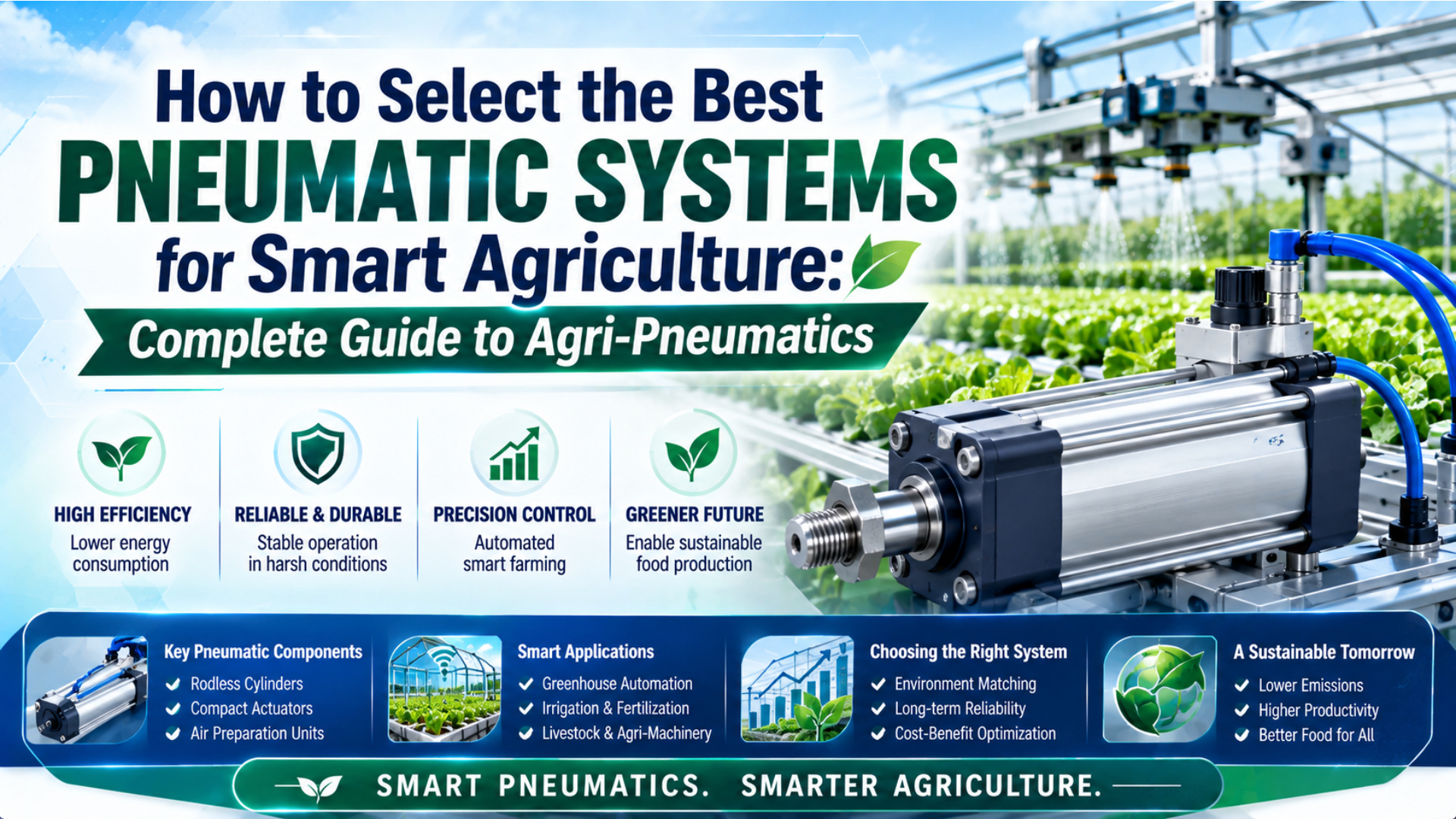
The best pneumatic system for smart agriculture is the one matched to a defined motion, load, duty cycle, environment, air source, safe state, and maintenance plan. Start with the function. Then size the actuator and air path as one system, verify every exposed component, and test the installed machine under its real operating and cleaning conditions.
Smart agriculture is not one pneumatic application. A greenhouse roof vent, seed gate, produce sorter, livestock feeder, and PWM spray nozzle have different energy sources and failure consequences. Some need compressed-air actuators. Some use electric or hydraulic power. A spray valve may control liquid rather than air, even though its coil is electrically actuated.
Agri-pneumatics is the use of compressed-air generation, treatment, control, and actuation in agricultural machinery or protected-crop systems. System boundary is the documented line separating that air circuit from electrical, hydraulic, liquid-spray, structural, and process functions.
Key Takeaways
- Define the machine function and safe state before choosing components.
- Size the actuator, valve, tubing, receiver, and compressor as one air path.
- Separate compressed-air motion control from liquid PWM spray control.
- Specify contamination, water, chemicals, temperature, and cleaning at component level.
- Release the system only after installed-machine testing and documented maintenance planning.
Where Do Pneumatic Systems Fit in Smart Agriculture?
ISO 4414:2010 applies to pneumatic systems used on machinery and explicitly includes reliable operation, maintenance, energy efficiency, and environment. Pneumatics fit smart agriculture when clean compressed air is available and the task benefits from controlled force, rapid repeatable motion, or simple actuation; they are not automatically right for every automated farm function (ISO).
Choose the energy technology before choosing a cylinder or valve:
| Agricultural function | First technology to evaluate | Why | Main verification question |
|---|---|---|---|
| Greenhouse vents, louvers, and curtains | Pneumatic or electric linear actuation | Repeated positioning with centralized control | What happens after air or power loss? |
| Seed, feed, and produce gates | Pneumatic actuation | Simple, fast linear motion | Can the actuator overcome peak friction and contamination? |
| Sorting, diverting, and packaging | Pneumatic actuation | High cycle rate and straightforward sequencing | Can the valve and air path meet the required stroke time? |
| Tractor implements and high-force mobile motion | Hydraulic actuation | High force density and existing hydraulic supply | Is load holding required when power is lost? |
| Precise programmable positioning | Electric servo actuation | Direct feedback and controllable position profile | Can the enclosure and transmission survive the environment? |
| Pesticide or fertilizer metering | Liquid valve and nozzle system | The controlled medium is liquid | Is flow characterized for the exact nozzle, formulation, and pressure? |
The first system boundary prevents a common specification error: an electrically operated liquid valve is not a pneumatic valve simply because it contains a solenoid. Likewise, an onboard compressor does not make every machine motion a good pneumatic candidate. Name the working fluid at every port before selecting hardware.
What Should You Define Before Selecting Components?
ISO 4414:2010 treats a pneumatic system across design, construction, modification, installation, adjustment, operation, maintenance, and cleaning. That lifecycle scope leads to the right starting document: a requirements sheet covering normal operation, abnormal conditions, cleaning, storage, servicing, and approved changes, rather than a shopping list of nominal component sizes (ISO).
Record these inputs before requesting a quotation:
- Function: what moves, clamps, diverts, meters, opens, or closes?
- Load: force direction, peak friction, gravity, wind, material buildup, shock, and frame deflection.
- Motion: usable stroke, target time, end positions, intermediate positions, and acceptable impact.
- Duty: cycles per minute, operating hours, seasonal idle time, and restart condition.
- Utility: pressure available at the machine, compressor capacity, receiver volume, electrical supply, and communications.
- Environment: dust, mud, rain, condensation, wash water, chemicals, temperature, sunlight, and vibration.
- Control: on/off or proportional command, feedback, diagnostic coverage, local manual control, and remote communication.
- Safe state: required position after air, power, signal, or controller loss.
- Maintenance: isolation points, access, competence, spares, cleaning method, and record ownership.
The worst credible sequence matters more than an annual average. A greenhouse actuator may sit in humid air, cool below the dew point overnight, cycle under solar heating, and receive a cleaning spray. A field unit may start cold, ingest dust, see fertilizer mist, then remain outdoors for months.
For exposed cylinders, use the dedicated weather-proof farming cylinder guide to build the component-level exposure map. This article stays at system level: deciding where the air comes from, how the circuit behaves, and what must be verified before release.
How Do You Size the Actuator and Air Supply?
ISO 15552 covers detachable-mount cylinders from 32 to 320 mm bore at a maximum rated pressure of 1,000 kPa, or 10 bar. Those dimensions support interchangeability, not application sizing. Select bore, valve, tubing, receiver, and compressor from effective pressure, load, speed, cycle rate, line loss, and safe-state requirements (ISO).
For a double-acting cylinder, start with theoretical force at the cylinder port:
Here, and are theoretical forces, is effective gauge pressure at the working chamber, is piston diameter, and is rod diameter. The result still needs allowances for friction, acceleration, alignment, pressure drop, uncertainty, and the required engineering safety margin.
For example, at produces about before deductions. Do not use compressor discharge pressure in this calculation unless measurements show that pressure reaches the cylinder while the machine is moving.
Next, calculate air demand from both chamber volumes, absolute-pressure ratio, cycle rate, and the number of actuators that can move simultaneously. Then check:
- peak flow needed to meet stroke time;
- valve conductance and exhaust restriction;
- tubing inside diameter, length, bends, and fittings;
- local receiver capacity for short demand peaks;
- compressor duty and recovery time;
- leakage allowance and future expansion;
- minimum port pressure during the worst simultaneous event.
Use the compressed-air pressure-drop calculator when long greenhouse branches or remote equipment place the actuator far from the receiver. The related cylinder air-consumption guide explains why reducing bore or pressure without checking load margin can create unstable motion instead of useful savings.
Greenhouse and Protected-Crop Architectures
University of Georgia guidance notes that hot-weather greenhouse ventilation may require one complete air exchange every 60 seconds. That is a ventilation-system target, not a cylinder specification, but it shows why vent geometry, wind load, opening time, feedback, and staged control must be defined before choosing a pneumatic actuator (UGA Extension).
A practical greenhouse pneumatic architecture usually contains:
- a compressor and receiver in a serviceable, protected location;
- automatic drainage and air treatment matched to ambient temperature;
- zoned isolation so one leak does not disable the entire greenhouse;
- local regulators and pressure indication at critical branches;
- valve manifolds protected from condensation and direct spray;
- position feedback where the controller must confirm vent or curtain state;
- manual release or override for recovery after control failure;
- an alarm for low pressure, excessive stroke time, or position disagreement.
Do all vents need proportional positioning? Often they do not. A staged on/off arrangement can be simpler when the environmental controller only needs discrete opening levels. Proportional pneumatic control makes sense when the process needs continuously variable position and the actuator, valve, sensor, and controller have been validated as a loop.
Use hysteresis and minimum on/off times to avoid rapid cycling around a temperature threshold. Separate environmental control logic from safety functions. A controller command is not proof of vent position, and a sensor signal is not an energy-isolation device.
Place local air storage only after deciding what it must accomplish. A receiver can supply a peak movement or support a controlled safe transition, but it also stores hazardous energy. Define its isolation, drainage, pressure protection, inspection, and behavior during maintenance.
The cheapest architecture is not the one with the fewest valves. It is the one that contains a leak or failed zone without losing every vent, documents the actual actuator position, and lets technicians isolate one branch without shutting down the whole crop environment.
How Should Remote and Outdoor Pneumatics Handle Contamination?
ISO 8573-1:2010 organizes compressed-air purity around three primary contaminant classes: particles, water, and oil. It also identifies gaseous and microbiological contaminants. For remote agricultural equipment, specify the required class and measurement location, because clean air at the compressor does not prove the same condition after a long exposed branch (ISO).
The system should manage contamination on both sides of the actuator. Outside, protect rods, sensors, connectors, coils, tubing, exhausts, and fittings from the documented exposure. Inside, prevent compressor intake dust, condensate, pipe debris, excess lubricant, and corrosion products from reaching valves and cylinders.
Match the pressure dew point to the coldest expected line condition. Air that leaves a warm compressor can cool in buried, shaded, or outdoor tubing. If water condenses downstream, a filter installed only at the compressor cannot reverse that phase change.
Route tubes away from sharp edges, animal traffic, vehicle contact, and standing water. Allow for thermal movement and service loops without creating low points that trap condensate. Protect exhaust silencers from mud and insects; a blocked exhaust can slow a cylinder even when supply pressure appears normal.
IEC 60529 classifies ingress protection for electrical enclosures up to 72.5 kV. Use a component’s tested IP code for the stated sensor, connector, coil, or enclosure configuration, not as proof that the complete mechanical assembly resists corrosion, chemical attack, or high-pressure cleaning (IEC).
The dust contamination control guide covers particle entry paths. For wet air problems, compare water separators and coalescing filters instead of treating the two devices as interchangeable.
Does PWM Spraying Make the System Pneumatic?
A 2026 USDA study tested five PWM duty cycles: 20%, 40%, 60%, 80%, and 100%. Flow mainly followed duty cycle, while droplet size and spray angle also depended on nozzle design and adjuvant chemistry. PWM is a control method; the valve’s working fluid determines whether the circuit is pneumatic or liquid (USDA ARS).
In a typical agricultural sprayer, an electrically actuated valve pulses liquid upstream of the nozzle. Compressed air may still appear elsewhere, such as in an air-assisted spray, actuator, or cleaning circuit, but those are separate energy and fluid paths. Label them separately on the schematic.
Do not specify one universal pulse frequency, response time, or droplet-size range for all UAV and ground sprayers. Validate the exact combination of:
- valve model and rated switching duty;
- nozzle type, orifice, and spray angle;
- upstream and downstream pressure behavior;
- pesticide or fertilizer formulation and adjuvant;
- duty-cycle range and command frequency;
- flight or vehicle speed and application rate;
- boom or nozzle height, wind, temperature, and humidity;
- droplet spectrum, coverage, angle, and off-target drift;
- product label and local application rules.
EPA’s drift program addresses risk assessment, labeling, applicator education, and drift-management activities. It does not supply a universal wind limit for every product or machine. Use the pesticide label, jurisdictional rules, nozzle data, and validated field procedure for the actual application (EPA).
If the PWM valve must cycle continuously, review the high-frequency valve selection guide for coil heating, switching life, driver behavior, and test conditions. Keep its compressed-air examples separate from liquid-media compatibility.
Materials and Seals: Qualification Before Sustainability Claims
ASTM D5338-15(2021) measures aerobic biodegradation under controlled thermophilic composting conditions and states that it does not simulate a particular composting system. It cannot prove that an assembled pneumatic seal will survive pressure, wear, fertilizer, sunlight, and temperature, then biodegrade on a farm within a claimed number of years (ASTM).
Select a seal compound from the actual medium and service envelope. NBR, HNBR, FKM, EPDM, polyurethane, PTFE-based systems, and specialty compounds have different strengths. The polymer family name alone is not enough; formulation, hardness, lubricant, pressure, surface finish, speed, temperature, and chemical concentration all affect performance.
Parker’s O-Ring Handbook and Trelleborg’s chemical-compatibility guide both use compound-specific ratings and limitations rather than one universal “agricultural seal.” Treat their tables as screening data, then obtain written confirmation for the exact material and medium (Parker, Trelleborg).
Compostability and seal qualification answer different questions. A disposal test does not establish dynamic sealing life, and a long-life seal does not establish an approved end-of-life claim. A sustainable design needs both service evidence and a disposal pathway, each tested under the correct standard.
For outdoor equipment, review more than the dynamic seal:
- rod and barrel materials;
- end caps, tie rods, fasteners, and mounting brackets;
- galvanic pairs and drainage paths;
- rod scraper and contamination shield;
- lubricant compatibility and relubrication policy;
- sensor housing, cable jacket, connector, and labels;
- tubing and fitting resistance to ultraviolet exposure and chemicals.
Use the cylinder seal-material comparison to structure supplier questions. Do not approve a substitute based only on matching color, hardness, or base-polymer abbreviation.
What Safety and Fail-Safe Decisions Belong in the Design?
ISO 4414:2010 addresses significant pneumatic hazards over the system lifecycle. In the United States, OSHA also identifies pneumatic pressure as hazardous energy where 29 CFR 1910.147 applies. Agricultural operations and jurisdictions can have different legal coverage, so the machine’s formal risk assessment and applicable rules must govern the final isolation method (ISO, OSHA).
Define failure behavior for each function:
| Failure | Required decision | Typical design options to evaluate |
|---|---|---|
| Air supply loss | Move, hold, or release? | Spring return, rod lock, counterbalance, mechanical latch, controlled vent |
| Electrical power loss | Which valve state is safe? | Monostable valve, stored-energy transition, independent safety circuit |
| Signal or network loss | Continue, stop, or return? | Timeout, local fallback, maintained last state only when justified |
| Tube rupture or major leak | How is the zone contained? | Branch isolation, flow monitoring, check valve where appropriate |
| Sensor disagreement | Can motion continue? | Plausibility check, alarm, inhibited command, manual recovery |
| Exhaust blockage | How is slow or trapped motion detected? | Stroke-time monitoring, pressure sensing, protected exhaust |
| Manual servicing | How is energy isolated and verified? | Lockable supply isolation, bleed, pressure indication, mechanical restraint |
A closed valve does not necessarily remove trapped pressure. Gravity, springs, raised vents, linkages, and compressed gas can remain hazardous after the compressor stops. The maintenance procedure must identify every stored-energy source, provide isolation and dissipation steps, and verify the safe condition before work begins.
Do not use the PLC, HMI, remote command, or ordinary directional valve as the only maintenance isolation unless the applicable risk assessment and rules explicitly permit that arrangement. Provide local, identifiable isolation that matches the machine’s service tasks.
The RFQ and Acceptance Gate
A useful smart-agriculture RFQ has at least 12 controlled fields: function, load, stroke, speed, duty, air supply, environment, chemicals, control, safe state, maintenance, and acceptance tests. ISO 4414 supplies the system-safety boundary, while IEC 60529 shows why enclosure evidence must stay tied to the exact tested component (ISO, IEC).
Send suppliers a completed data sheet, not the phrase “agricultural grade.” Request:
- complete part numbers and option codes;
- performance curves or rated data at the stated pressure;
- valve flow data and switching conditions;
- approved seal, lubricant, tube, and fitting materials;
- temperature limits for the complete configuration;
- electrical voltage tolerance and connector details;
- component-specific ingress test evidence;
- chemical-compatibility statements with limitations;
- required filtration, drying, lubrication, and mounting practices;
- service instructions, inspection criteria, and spare parts;
- declarations, certificates, and standards actually applicable to the destination market;
- a list of assumptions and exclusions.
Acceptance testing should reproduce the critical duty sequence. Measure port pressure during motion, stroke time, position, leakage, current, temperature where relevant, and recovery after faults. Repeat functional checks after dust, water, chemical, temperature, vibration, and cleaning exposures that reflect the real machine.
Use a requirements-to-evidence matrix with four columns: requirement, supplier evidence, installed test, and approval owner. If a component changes, reopen the affected rows. This prevents an apparently minor substitution of a seal, valve, silencer, connector, or tube from bypassing system validation.
The Department of Energy notes that pressure drop and leaks can reduce useful system pressure and increase compressor work. For remote sites, baseline demand and leakage after commissioning so later changes can be diagnosed from measurements instead of guesswork (DOE).
The system is ready when another engineer can trace each requirement to a configured component, source document, installed test result, maintenance task, and approved exception. That is a stronger selection method than ranking products by nominal bore, headline IP code, or purchase price alone.
Smart Agriculture Pneumatic System FAQs: What Should Buyers Ask?
ISO 8573-1 identifies particles, water, and oil as the three primary compressed-air purity classes, while ISO 4414 covers pneumatic-system hazards and lifecycle design. The most useful buyer questions therefore test both performance and system evidence: air quality, failure behavior, circuit boundaries, and installed validation rather than isolated component labels.
Is a pneumatic system always the best choice for greenhouse vents?
No. Pneumatics work well when compressed air is already available, movement is relatively simple, and the safe state can be engineered. Electric actuators may suit precise positioning or distributed sites better. Compare wind load, travel time, feedback, zoning, air-loss behavior, maintenance access, and total utility cost before choosing.
What compressed-air quality class should agricultural equipment use?
There is no universal agricultural class. Specify particle, water, and oil limits from the most sensitive valve, actuator, process, and minimum line temperature, then name the measurement point. Confirm that treatment remains effective at peak flow and after long outdoor runs where cooling can create downstream condensation.
Can an IP rating prove that a complete pneumatic cylinder is weather-proof?
No. IEC 60529 applies enclosure protection to the tested electrical configuration. A sensor or valve coil rating does not establish corrosion resistance, rod-seal durability, chemical compatibility, exhaust protection, or washdown performance for the complete assembly. Request component-specific evidence and validate the installed machine under its defined exposure sequence.
Are biodegradable polymers ready to replace conventional pneumatic seals?
Only when the exact compound and seal design have pressure, wear, temperature, lubricant, chemical, aging, and disposal evidence for the application. ASTM D5338 composting results do not establish dynamic sealing life or field biodegradation. Treat emerging materials as qualification projects, not drop-in substitutes based on a polymer-family claim.
Sources and technical references
- ISO 4414:2010, Pneumatic fluid power, general rules and safety requirements, accessed 2026-07-27.
- ISO 8573-1:2010, Compressed air contaminants and purity classes, accessed 2026-07-27.
- ISO 15552:2018, Detachable-mount cylinders, 1,000 kPa series, accessed 2026-07-27.
- IEC 60529, Degrees of protection provided by enclosures, accessed 2026-07-27.
- USDA ARS, PWM nozzle duty-cycle, nozzle, and adjuvant study, 2026.
- US EPA, Reducing Pesticide Drift, accessed 2026-07-27.
- University of Georgia Extension, Greenhouses: Heating, Cooling and Ventilation, accessed 2026-07-27.
- ASTM D5338-15(2021), Controlled composting biodegradation test, accessed 2026-07-27.
- Parker O-Ring Handbook, accessed 2026-07-27.
- Trelleborg Chemical Compatibility Guide, accessed 2026-07-27.
- U.S. Department of Energy, Improving Compressed Air System Performance, accessed 2026-07-27.
The site’s technical scope and ownership are described on the About page. Readers can submit technical corrections through Contact.