

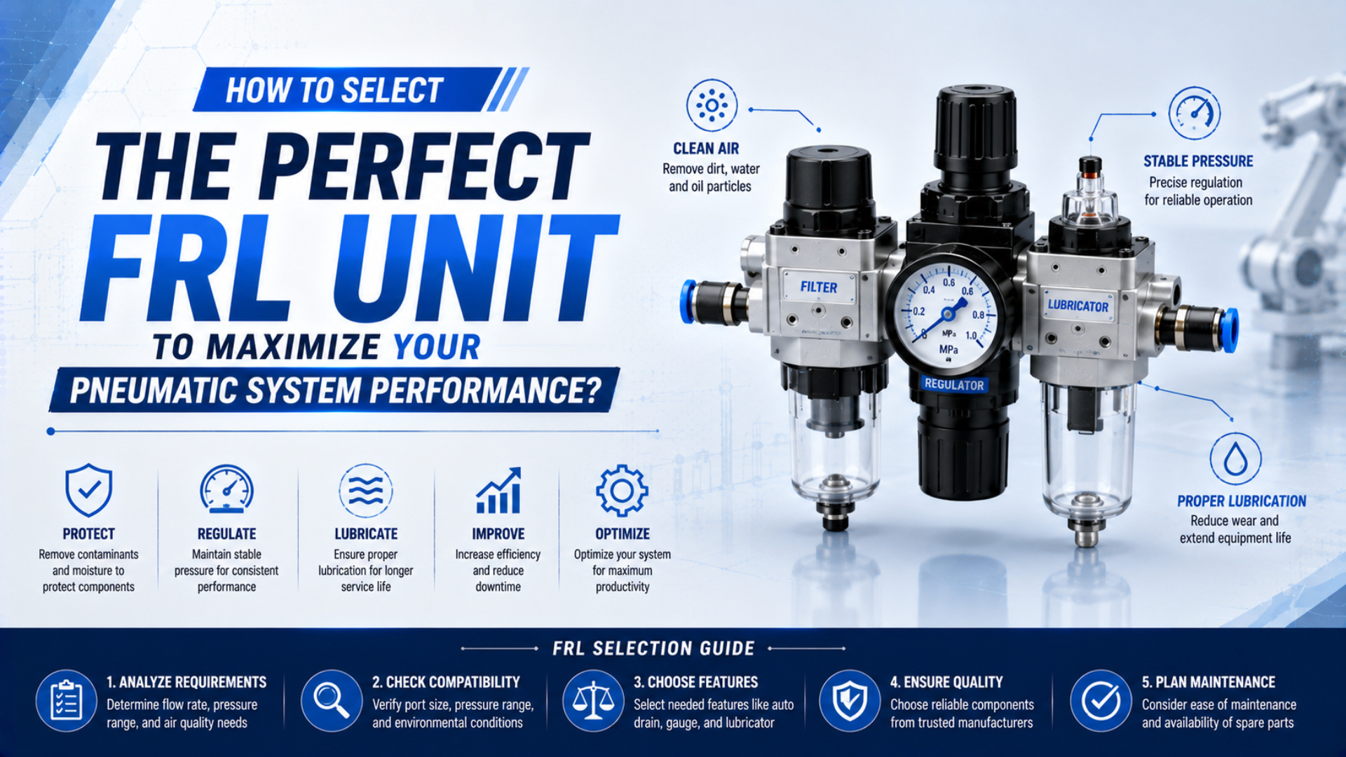
Select an FRL unit from the machine’s required air quality, peak simultaneous flow, minimum dynamic pressure, regulator behavior, environment, and lubrication policy. Port size alone is not a capacity rating. A three-piece filter-regulator-lubricator is also not automatically better than a filter-regulator when downstream equipment is designed for non-lubricated air.
CAGI explains that pressure drop exists only while air is flowing and increases as flow rises through a restriction. The practical consequence is simple: compare each candidate at the real inlet pressure and peak event flow, then reserve enough pressure for piping, valves, and the actuator (CAGI Compressed Air System Design, 2021).
Key Takeaways
- Specify particles, water, and oil separately under ISO 8573-1.
- Select from flow curves at peak demand, not port size or average consumption.
- Add a lubricator only when the downstream equipment manufacturer requires it.
- Verify dynamic outlet pressure, drains, materials, orientation, and service access after installation.
What Data Should Be Collected Before Selecting an FRL?
ISO 6953-1:2024 is an 11-page standard covering supplier literature for pressure regulators up to 25 bar inlet and 16 bar adjustable outlet, while filter-regulators in its scope are rated up to 16 bar. Selection therefore starts with documented operating limits and comparable supplier data, not a connection thread alone (ISO 6953-1:2024).
Create one operating-point sheet before requesting a model number. It should distinguish normal conditions from the worst approved condition because an FRL that looks adequate at average flow can starve a machine during simultaneous motion.
| Selection input | Record this value | Why it changes the FRL |
|---|---|---|
| Supply pressure | minimum, normal, and maximum at the FRL inlet | sets regulator headroom and component pressure rating |
| Machine pressure | minimum dynamic pressure and normal setpoint | defines the usable pressure-drop budget |
| Demand | peak simultaneous free-air flow, average flow, and duty cycle | determines the required point on each flow curve |
| Air quality | particle, water, and oil class at the point of use | determines filtration and upstream treatment |
| Environment | temperature, chemicals, washdown, sunlight, vibration, and corrosion exposure | controls bowl, seal, guard, and housing choices |
| Condensate | expected liquid load and available drain connection | determines manual, semi-automatic, or automatic drain suitability |
| Lubrication | downstream OEM requirement and approved oil | determines whether the L stage is allowed |
| Safety | isolation, soft-start, exhaust, reset, and lockout requirements | determines supporting modules and circuit architecture |
| Service | mounting orientation, bowl clearance, gauge visibility, and element access | determines whether the assembly can be maintained correctly |
Use the machine sequence to find peak flow. Do not sum every catalog consumption value unless every device can demand air at the same instant. Conversely, do not use average compressor consumption for a short clamp, ejector, or blow-off event. The detailed method belongs in the FRL unit sizing guide.
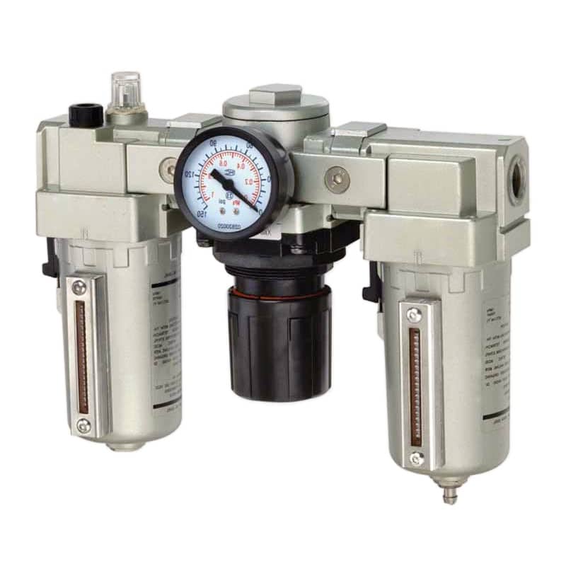
A three-piece FRL is one possible configuration. The application still has to justify the filter grade, regulator range, bowl design, drain, lubricator, and flow capacity.
From our work reviewing FRL selections, we found that one undocumented compatibility limit can outweigh several favorable catalog features. Treat each requirement as a gate, not as a feature score. High nominal flow cannot rescue a bowl that is incompatible with the cleaning agent. One failed air-quality, pressure, material, or service gate is enough to reject the candidate.
Selecting Filtration Without Losing Usable Pressure
ISO 8573-1:2010 uses nine pages to classify compressed-air purity for particles, water, and oil independently. A micron label addresses only part of that specification, so a nominal 5 µm filter cannot by itself prove a complete ISO 8573-1 purity class at the machine inlet (ISO 8573-1:2010).
Start from the most sensitive downstream component and the required point-of-use purity. Then identify what the local FRL can remove and what must be handled upstream by a separator, dryer, coalescing stage, adsorber, or another treatment process. The ISO compressed-air quality guide explains how to write the three-part purity specification.
A particulate filter captures solid contamination within its stated rating and separates bulk liquid according to its design. A coalescing filter targets fine liquid aerosols and fine particles, normally with suitable prefiltration. It is not a substitute for a dryer when the required water-vapor pressure dew point is below what the compressor room supplies. See the coalescing-filter guide for that boundary.
Pressure drop must be checked on the manufacturer’s curve. CAGI gives this same-component screening relationship for similar conditions:
Here, and are pressure drops at flows and . The relationship shows why doubling flow can produce roughly four times the pressure drop through the same restriction. It does not replace the supplier’s clean-element curve, regulator curve, or dirty-element service limit.
Choose the largest of three flow cases: production peak, approved future expansion, and the demand that occurs during a safe restart or purge. Check both clean and service-limit pressure drop. Oversizing can lower pressure loss, but an unnecessarily large housing increases cost and can make drains, brackets, bowls, and spares harder to standardize.
How Should Regulator Flow and Droop Be Compared?
ISO 6953-2:2024 devotes 39 pages to standardized tests and presentation methods for regulators and filter-regulators. Its purpose is to support comparison and proper application, which is why a single “maximum flow” number cannot replace forward-flow, relief-flow, pressure-regulation, and hysteresis data at the intended operating point (ISO 6953-2:2024).
Regulator droop is the reduction in outlet pressure as forward flow increases from the set condition. Compare candidate curves at the specified inlet pressure, outlet setpoint, and peak flow. Two regulators with the same port thread can have different valve areas, springs, diaphragms, relieving behavior, and dynamic response.
Build the pressure budget explicitly:
In this relationship, is the lowest approved inlet pressure during production, includes the branch line and connectors, and comes from the candidate’s flow data at peak demand. The resulting must remain above the machine’s verified minimum dynamic pressure.
Estimate the piping portion separately with the Compressed Air Pressure Drop Calculator, but enter the FRL loss from its manufacturer curve. A pipe calculator cannot predict filter loading, regulator droop, or internal module restrictions.
Also specify:
- required adjustment range, with the normal setpoint away from either extreme;
- relieving or non-relieving operation;
- pressure gauge range and accuracy suitable for the setpoint;
- reverse-flow requirement during exhaust or maintenance;
- pilot-operated regulation when demand or inlet variation exceeds direct-acting performance;
- lockable adjustment when unauthorized changes create process or safety risk.
Does the Machine Need a Lubricator?
SMC’s AL800/900 catalog shows why lubricator selection is model-specific: listed minimum operating flows range from 460 to 1,800 L/min depending on model and port, and the stated test conditions include inlet pressure, oil, temperature, needle position, and drip rate. A generic drops-per-minute rule cannot replace that data (SMC AL800/900 Catalog).
Add a lubricator only when the downstream tool or component manufacturer requires continuous oil-mist lubrication. Many modern valves and cylinders are assembled with grease intended for non-lubricated compressed air. Introducing line oil without checking compatibility can wash out grease, attract contamination, affect seals, and create unwanted oil at the exhaust.
Ask four questions:
- Does every downstream device on this branch permit or require line lubrication?
- What exact oil specification, viscosity, and additive restrictions does each manufacturer state?
- Does actual consumption stay above the lubricator’s minimum operating flow during the periods when oil delivery is required?
- Can oily exhaust contact food, medicine, electronics, sensors, paint, packaging, or a clean process?
In our experience reviewing applications, “the old machine always had a lubricator” is not enough evidence to keep one. We trace every downstream component, check its current manual, and separate tools that require oil from components that should remain non-lubricated. Splitting those branches is often clearer than compromising both with one shared FRL.
When lubrication is approved, use the exact oil named by the equipment and lubricator manufacturers. The VG32 versus VG68 pneumatic-oil guide explains why viscosity labels alone do not prove additive, seal, temperature, or atomization compatibility.
Bowl, Drain, Material, and Environment Options
SMC’s modular AC catalog states that standard filter, filter-regulator, and lubricator bowls and the lubricator sight dome are polycarbonate, then provides separate chemical warnings and bowl-protection options. That is a useful reminder: transparent bowl convenience does not establish compatibility with every solvent, oil, coolant, washdown chemical, temperature, or impact exposure (SMC AC Series Catalog).
Select the bowl and seals from the real environment. Record ambient and air temperature, pressure, chemical exposure, ultraviolet exposure, cleaning method, vibration, corrosion risk, and local mechanical-impact risk. Use a metal bowl or guard where the verified conditions require it, but confirm drain type, level visibility, and maintenance access rather than assuming metal solves every hazard.
Drain behavior deserves its own decision:
- Manual drain: suitable only when inspection and draining can be performed before the bowl reaches its limit.
- Semi-automatic drain: check whether the selected design drains when pressure falls and whether the machine actually depressurizes often enough.
- Automatic drain: verify its operating pressure range, condensate capacity, failure behavior, discharge connection, and maintenance requirements.
The manual versus semi-automatic FRL drain guide covers the operating-state distinction. For bowl material limits, use the polycarbonate versus metal bowl guide as a starting checklist, then confirm the selected series data.
How Should Modular FRL Components Be Arranged?
ISO 4414:2010 is a 38-page standard covering pneumatic-system hazards and requirements across design, assembly, installation, adjustment, operation, maintenance, cleaning, reliability, energy efficiency, and environment. FRL order therefore has to support the complete machine function and safe servicing, not merely reproduce an F-R-L label (ISO 4414:2010).
The normal air-treatment sequence is isolation or soft-start as required, particulate or water separation stages, regulator, and lubricator last when lubrication is permitted. Exact safety-valve placement and exhaust paths depend on the machine’s risk assessment. A pressure gauge, pressure switch, distribution block, or flow sensor may belong at a point where it observes the required physical condition.
Observe flow arrows and mounting orientation. Support the assembly with the specified brackets rather than asking threaded piping to carry its mass. Leave room to remove bowls and elements, read the gauge, operate the lockout, and collect drain discharge. The modular versus standalone FRL guide covers the serviceability tradeoff.
Do not install an unrestricted bypass around an air-treatment or safety function merely to simplify maintenance. If continuity is essential, design a controlled redundant path with equivalent treatment, isolation, interlocking, and verification appropriate to the risk.
FRL Selection Matrix for RFQs and Supplier Comparison
ISO 6953-1:2024 defines required supplier-literature characteristics for regulators and filter-regulators within an 11-page framework. A useful RFQ should therefore request operating curves, test conditions, pressure limits, adjustment range, relieving behavior, materials, and marking data rather than accepting one nominal-flow headline as proof of application fit (ISO 6953-1:2024).
Use a compliance matrix so every supplier answers the same question.
| Decision gate | Required supplier evidence | Reject or clarify when |
|---|---|---|
| Air quality | filter type, rated particle removal, coalescing data, drain details | only a micron label is supplied |
| Peak flow | curve at the intended inlet pressure and acceptable pressure drop | only port size or an unexplained maximum flow appears |
| Regulation | forward-flow curve, set range, droop, relief behavior, gauge data | outlet pressure is stated only at zero flow |
| Lubrication | minimum flow, approved oil, delivery method, refill procedure | a universal drip setting is proposed |
| Environment | temperature, pressure, bowl, guard, seals, chemical limits | material compatibility is undocumented |
| Configuration | flow direction, bracket, joining kit, module order, exhaust route | mixed series are combined without approval |
| Maintenance | element part number, service indicator, bowl clearance, drain service | routine service requires disturbing unsafe energy |
| Compliance | applicable declarations, markings, test method, certificates | a component claim is transferred to the whole machine |
Do not add independent safety margins to every row without checking their combined effect. Oversizing the filter, regulator, ports, and tubing can be sensible, but multiplying arbitrary allowances can produce a bulky assembly with poor low-flow lubricator operation and unnecessary inventory. State one design condition, then verify every component against it.
How Should the Installed FRL Be Commissioned?
CAGI illustrates a filter that rises from 4 psig pressure drop at 350 cfm to about 16 psig when flow doubles to 700 cfm under the same-component square-law example. Commissioning must therefore measure the installed system during peak demand; a correct static gauge reading cannot prove adequate dynamic flow (CAGI Compressed Air System Design, 2021).
Record inlet pressure, regulated outlet pressure, and pressure at the critical machine point on the same time base. Run the most demanding approved sequence and confirm the minimum dynamic pressure remains above the validated machine requirement.
Commissioning should also cover:
- leak inspection at module joints, gauges, drains, and threaded connections;
- regulator setpoint, lock, relieving behavior, and recovery after a demand step;
- drain operation under the actual pressure cycle and condensate load;
- filter differential-pressure indication or baseline pressure-drop record;
- lubricator delivery only when required, at actual operating flow;
- soft-start, isolation, exhaust, reset, and lockout behavior where fitted;
- bowl, guard, bracket, flow arrow, orientation, and service clearance;
- part numbers and settings entered into the maintenance record.
For ongoing work, the FRL setting and maintenance guide explains dynamic pressure checks and condition-based service. Recommission after changing the filter grade, regulator, port adapter, tubing, drain, lubricant, safety valve, machine cycle, or peak simultaneous demand.
FRL Selection FAQs: What Should Engineers Verify?
Engineers should verify three separate references: ISO 8573-1 classifies particles, water, and oil; ISO 6953-1:2024 defines supplier-literature characteristics across 11 pages; and ISO 6953-2:2024 standardizes comparison tests across 39 pages. Together they show why FRL selection needs air-quality requirements, comparable performance data, and installed measurements.
Can FRL size be selected from the port thread?
No. A G1/2 or 1/2-inch thread identifies a connection, not the pressure available at peak flow. Compare the filter pressure-drop and regulator forward-flow curves at the actual inlet pressure, outlet setpoint, and simultaneous demand. Confirm the complete assembly, adapters, and piping keep dynamic machine pressure above its verified minimum.
Does finer filtration always improve a pneumatic system?
No. Filtration should meet the required particle, water, and oil specification without consuming the available pressure budget. A finer element may add pressure loss and still cannot replace a dryer or another treatment stage. Select the treatment train from the point-of-use purity requirement, then check clean and service-limit performance at peak flow.
Should every FRL include a lubricator?
No. Install a lubricator only when downstream equipment requires compatible, continuous oil-mist lubrication. Check every device on the branch, the approved oil, the lubricator’s minimum operating flow, and exhaust contamination risk. Components designed for non-lubricated air may perform worse if line oil washes out assembly grease or affects seals.
Is a metal bowl always safer than a polycarbonate bowl?
No single bowl material is best for every application. Compare working pressure, temperature, chemical exposure, impact risk, corrosion, inspection needs, guard options, and drain compatibility against the selected series documentation. A metal bowl can improve resistance in some conditions, but it does not remove the need for correct mounting, isolation, and maintenance access.
When should an FRL filter element be replaced?
Replace it according to the selected manufacturer’s differential-pressure limit, condition indicator, maintenance instructions, or approved interval, not a universal pressure-drop number. Establish a clean-element baseline at the operating flow, trend the installed restriction, and investigate contamination or condensate loading. Recheck dynamic outlet pressure after service to confirm the machine still meets its requirement.
Sources and technical references
- ISO 8573-1:2010, compressed-air contaminant categories and purity classes. Retrieved 2026-07-27.
- ISO 6953-1:2024, supplier-literature and marking requirements for regulators and filter-regulators. Retrieved 2026-07-27.
- ISO 6953-2:2024, standardized regulator and filter-regulator comparison tests. Retrieved 2026-07-27.
- ISO 4414:2010, pneumatic-system rules and safety requirements. Retrieved 2026-07-27.
- CAGI Compressed Air System Design, system pressure drop, peak-flow selection, and the same-component flow example. Retrieved 2026-07-27.
- SMC Modular F.R.L. Units AC Series, materials, modular configuration, handling precautions, and product data. Retrieved 2026-07-27.
- SMC Large Flow Lubricator AL800/900, model-specific minimum flow, oil, pressure, and temperature conditions. Retrieved 2026-07-27.