

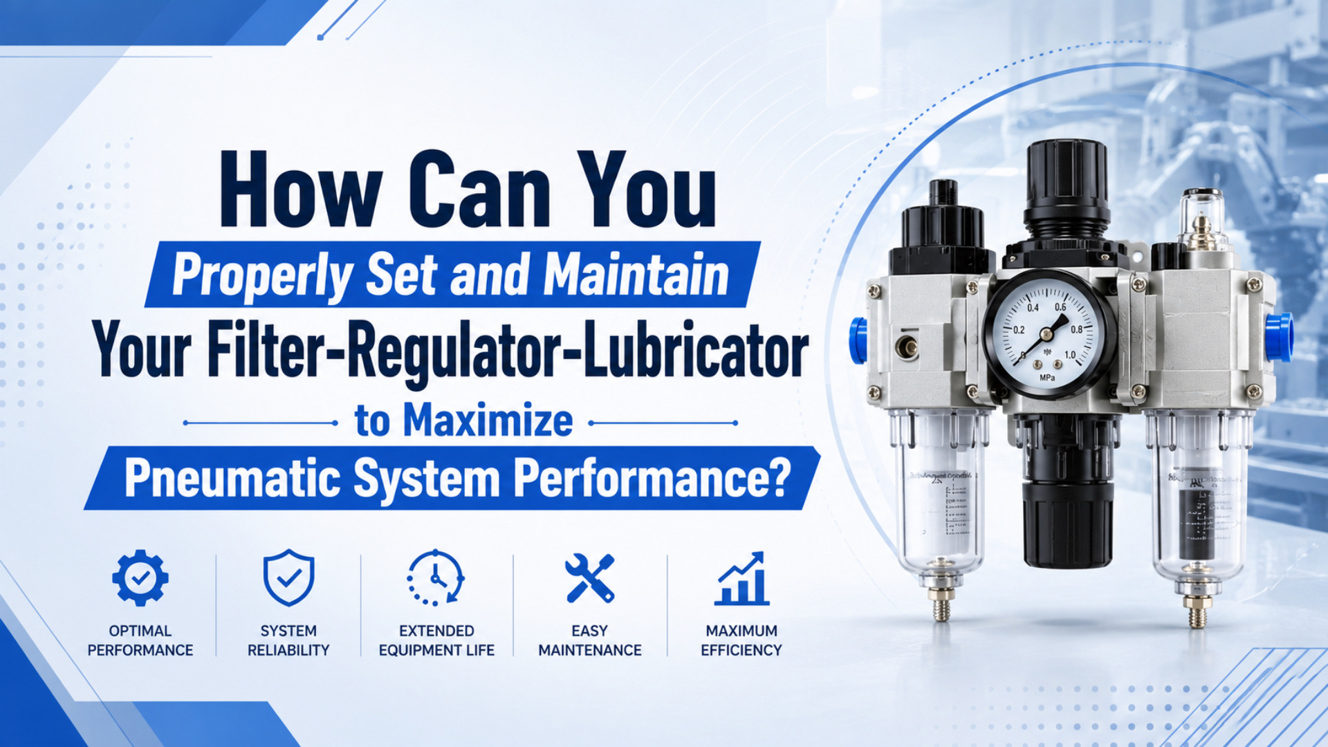
Set and maintain a filter-regulator-lubricator by following the airflow arrow and mounting its bowls correctly. Set the regulator from the machine’s dynamic pressure requirement, then service each stage at the exact model’s condition limit. Add the lubricator only when every downstream component permits or requires oil. An FRL unit is a point-of-use assembly that filters air, controls downstream pressure, and optionally adds oil. Good FRL setup and maintenance connects every adjustment to a manufacturer instruction, a live reading, and an acceptance test. It doesn’t rely on a fixed pressure margin, calendar alone, or drops per machine cycle.
Key Takeaways
- Set pressure from the minimum required during peak flow, not from a fixed margin below maximum.
- Add oil only when downstream manuals permit it, then follow their lubricant specification.
- Replace filter elements at the installed model’s pressure-drop or time limit.
What Should You Verify Before Installing an FRL?
Parker’s 2FR300D instructions list 6 installation actions: keep the unit accessible, clean the upstream line, place it close to protected equipment, follow the body arrow, mount the bowl vertically, and install gauges correctly (Parker filter-regulator instructions, retrieved 2026-07-14). Verify those points plus system compatibility before admitting air.
Start with the nameplate and manual for the exact modules. Record maximum inlet pressure, regulator range, temperature limits, bowl material, port size, filtration grade, drain type, and permitted oil. The lowest applicable limit controls the assembly. Flow matters too. A large port doesn’t prove that the regulator will hold pressure during a fast cylinder stroke or an air-blow event. If the unit hasn’t been sized yet, use the separate FRL sizing guide before commissioning it.
Check the installation environment before choosing the mounting point:
- Leave bowl-service clearance.
- Check bowl-material compatibility with cleaning agents, compressor oils, process chemicals, direct sunlight, impact risk, temperature, and the required guard.
- Route every drain to safe condensate collection.
- Support the piping independently so hose pull, pipe misalignment, weight, and vibration aren’t transferred into the FRL body.
- Keep the gauge, sight dome, drain level, labels, and shut-off visible.
Before opening a line or bowl, use the site’s approved energy-control procedure. A closed valve isn’t enough if downstream pressure or trapped actuator energy remains.
How Do You Install a Filter-Regulator-Lubricator in the Correct Order?
An FRL has 3 functions arranged in process order: filter, regulator, then lubricator. Festo describes the filter as removing condensate and coarse dirt, the regulator as controlling pressure, and the lubricator as dosing oil (Festo FRL overview, retrieved 2026-07-14). Install only the functions the downstream equipment actually requires.
Filtration keeps collected liquid and particles out of the regulator. Pressure is controlled next. The optional lubricator stays last so its oil reaches only the intended downstream branch. Don’t rely on left-to-right appearance; follow every module’s arrow and confirm that connectors, seals, brackets, and adapters share the required pressure class. A point-of-use filter also doesn’t replace a plant dryer when controlled pressure dew point is required. The air-source treatment guide explains how particle, water, and oil requirements change the treatment train.
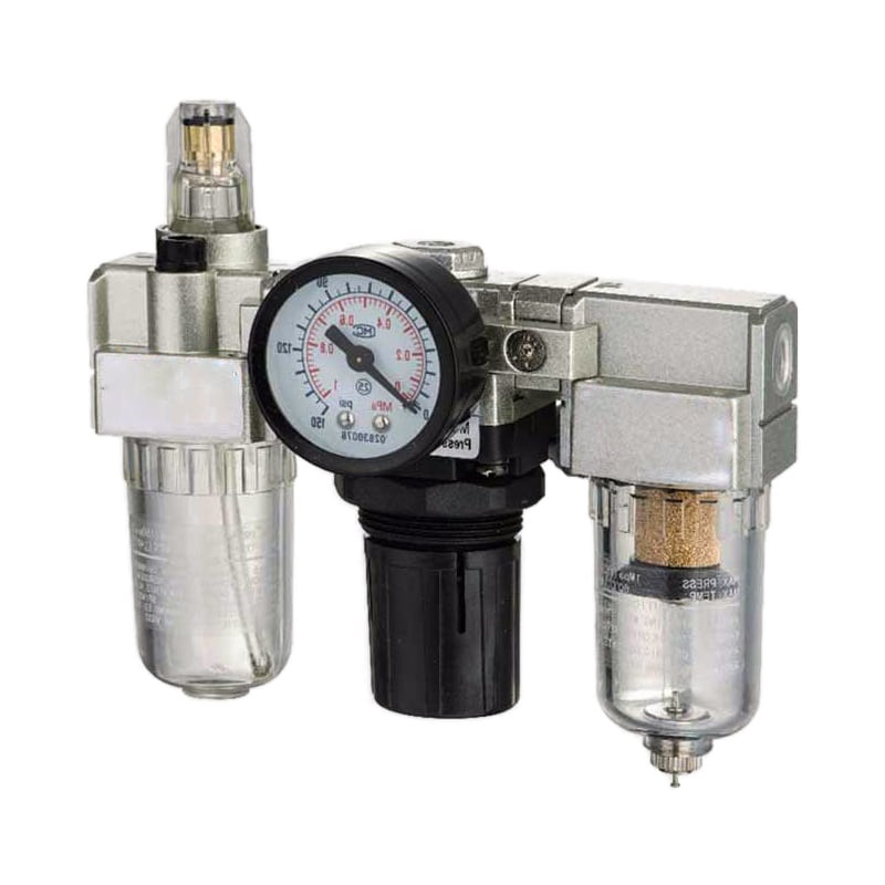
Treat the FRL as a boundary between plant air and machine air. The inlet record describes what the plant supplies. The outlet record describes what the machine receives. That boundary makes it easier to separate an upstream capacity problem from a local filter, regulator, drain, or lubrication problem.
How Should You Set Regulator Pressure?
Set regulator pressure from the machine’s minimum dynamic requirement, then confirm the exact regulator can hold it at peak flow. ISO 6953-2:2024 standardizes supplier test methods for comparing regulator and filter-regulator characteristics (ISO 6953-2, 2024). A fixed 10 or 15 psi reduction from a component maximum isn’t a valid universal method.
Use this sequence:
- Put the adjustment low.
- Pressurize through the approved start-up arrangement, keep personnel clear of motion, and stop if leakage or unexpected movement appears.
- Raise pressure gradually until the machine meets its verified requirement.
- Reproduce the highest simultaneous-flow event while logging the FRL inlet, FRL outlet, and critical valve or actuator inlet on the same time base.
- Lock the adjustment; record static and minimum dynamic pressure with the test load.
Parker’s 2FR300D instructions say that when reducing a setting, the operator should first go below the desired value and then adjust upward to the final pressure. That procedure reduces uncertainty from regulator mechanics, but it doesn’t replace a dynamic-flow test. For example, a regulator that holds 6 bar at rest but falls to 5.1 bar during clamp extension hasn’t passed, even if both values remain below its maximum rating. Record both set pressure and minimum working pressure. The first is an adjustment. The second is evidence. A regulator can display the intended setpoint at rest and still fail the application because its outlet pressure droops during the peak event.
When specifications mix bar, MPa, and psi, use the Pressure Converter to normalize the values. Never confuse a maximum component rating with the minimum pressure required to perform the task.
Does Every Pneumatic System Need a Lubricator?
No. Parker’s C05 cylinder catalog covers models with maximum working pressure up to 10 bar and still states that they’re pre-lubricated and normally need no further lubrication (Parker C05 catalog, retrieved 2026-07-14). Treat the lubricator as an application-specific option, not an automatic third stage on every pneumatic branch.
Build a lubrication policy from every downstream manual. Air tools, motors, cylinders, valves, grippers, instruments, vacuum equipment, and process nozzles may have different requirements. If one branch feeds incompatible policies, split the branch instead of sending oil to everything.
| Downstream requirement | FRL decision | Evidence to retain |
|---|---|---|
| Every device permits dry, pre-lubricated operation | Use filter-regulator without oil addition | Current manuals and specified air-quality limits |
| One or more devices require continuous oil mist | Add a correctly sized lubricator for that dedicated branch | Approved oil, delivery method, flow range, and inspection procedure |
| Process prohibits oil carryover | Keep lubricator out and review upstream oil removal | Purity requirement at the named measurement point |
| Existing branch has already received oil | Review all device instructions before stopping it | Service history, oil type, seal condition, and manufacturer guidance |
SMC’s precautions show why the decision can’t be generalized: many products are lubricated for life, while specified products may use ISO VG32 turbine oil. Once introduced oil washes away factory lubricant, the supply may need to continue (SMC lubrication precautions, retrieved 2026-07-14).
Check viscosity, base oil, additives, seal compatibility, process restrictions, temperature, and manufacturer approval. Automotive or detergent oils may be prohibited.
How Do You Set Lubricator Delivery Without Over-Oiling?
Adjust a lubricator only while air is flowing at a stable, representative rate. Parker’s 1M301 instructions give 1 drop per minute for every 10 to 15 SCFM as a starting point for that specific constant-density lubricator (Parker lubricator instructions, retrieved 2026-07-14). Other designs and downstream devices can require a different oil and delivery rate.
Sight-dome drops are measured per unit time, not per machine cycle. Cycle-based rules fail when stroke volume, duty cycle, simultaneous demand, or idle airflow changes. First confirm that the lubricator’s flow range matches the branch; a lubricator can meter poorly below its minimum operating flow. For example, a starting rate published for one constant-density lubricator at 10 to 15 SCFM doesn’t establish the correct setting for another design, flow range, or downstream requirement.
Follow this six-step check:
- Use only approved oil.
- Restore air through the approved procedure, keep the work zone clear, and run a stable flow that represents actual production demand.
- Start lean; count drops for a full minute at stable flow.
- Compare delivery with the lubricator and downstream-device instructions.
- Repeat the observation at low and high demand because pickup and transport can change with airflow, pipe length, elevation, branch geometry, and idle periods.
- Record oil, level, adjustment, flow condition, observed rate, and follow-up date.
Too much oil can foul silencers, sensors, exhausts, and processes. Too little leaves an oil-dependent tool unprotected. Verify stable consumption, no pooling, and acceptable downstream condition.
Oil delivery is a ratio tied to airflow, not a decoration on the regulator setpoint. If production demand changes, the oil-delivery check belongs in the change review even when nobody touched the adjustment knob.
Condition-Based FRL Maintenance
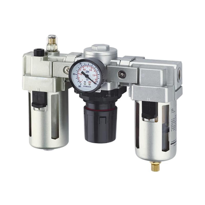
CAGI gives 2 general compressed-air filter triggers: replace the element at 5 to 7 psig differential pressure or at least every 6 months (CAGI pressure-drop brief, retrieved 2026-07-14). Parker’s cited miniature filter instead uses 10 psig, which proves the maintenance limit must come from the exact filter and site conditions.
A calendar starts the route; measured condition decides the work. Dirty or humid service may need earlier attention, and automatic drains need different checks from manual drains.
| Check | Evidence to record | Service trigger |
|---|---|---|
| Filter condition | Inlet and outlet pressure during the same peak event | Exact model’s differential-pressure limit, damage, or required time interval |
| Bowl and drain | Liquid level, drain discharge, cracks, haze, guard condition, leakage | Warning level, failed drain, incompatible exposure, or physical damage |
| Regulator | Static setpoint, minimum dynamic outlet pressure, creep at zero demand | Unstable output, excessive droop, leakage, damaged gauge, or failed lock |
| Lubricator | Oil identity, level, drop rate at stated flow, downstream evidence | Wrong oil, no delivery, unexpected consumption, contamination, or prohibited carryover |
| Assembly | Brackets, modular clamps, fittings, labels, shut-off and dump function | Looseness, corrosion, unreadable warning, leakage, or failed safety function |
For a broader failure-isolation method, use the FRL reliability and diagnosis guide. This article stays focused on setup, condition checks, and documented return to service.
What Do Common FRL Readings Mean?
DOE illustrates condition monitoring with a compressed-air example in which a dirty coalescing filter rises from 2 psi to 6 psi pressure drop, adding 4 psi of avoidable loss (DOE compressed-air maintenance guide, retrieved 2026-07-14). Use that as a diagnostic pattern, not as a universal FRL acceptance limit.
| Observation | Likely boundary | Next check |
|---|---|---|
| Inlet and outlet fall together during production | Plant branch, storage, compressor control, or simultaneous demand | Measure farther upstream during the same event |
| Inlet holds while FRL outlet falls | Loaded filter, regulator droop, undersized unit, or internal fault | Measure filter differential and compare the exact forward-flow curve |
| FRL outlet holds while actuator inlet falls | Downstream tubing, fitting, valve, silencer, or manifold restriction | Move the pressure sensor downstream one segment at a time |
| Outlet rises slowly with no downstream flow | Possible regulator seat leakage or non-relieving behavior | Confirm regulator type and follow its service procedure |
| Oil use changes without an adjustment | Changed airflow, leak, blocked feed, wrong oil, or reservoir problem | Verify flow condition, sight rate, oil identity, and downstream evidence |
| Bowl fills repeatedly with liquid | Drain fault or excessive upstream moisture load | Check drain, dryer performance, pressure dew point, and piping layout |
Use the compressed-air pressure-drop calculator to estimate straight-pipe and fitting loss. It doesn’t model a loaded filter element or regulator droop, so compare its result with live measurements and the manufacturer’s FRL curves.
If water repeatedly reaches the bowl, review the pressure dew point guide and verify the dryer, drains, pipe temperature, and measurement point.
Safe Return-to-Service Record
OSHA 29 CFR 1910.147 treats pneumatic pressure as hazardous energy and requires isolation plus control of stored or residual energy before covered servicing work (OSHA 1910.147, retrieved 2026-07-14). A safe return-to-service record begins with verified isolation, then documents inspection, adjustment, leakage testing, and controlled recommissioning.
Follow the site’s validated procedure and the equipment manuals. At minimum, record:
- Record the work authorization.
- Identify every isolation point, stored-energy control, verification method, FRL module, replacement element, seal, approved oil, and changed part.
- Save before-and-after inlet pressure, static outlet pressure, minimum dynamic outlet pressure, and the exact test flow event.
- Note drain function, leakage result, regulator lock position, lubricator observation, and downstream cleanliness.
- Document the controlled restart sequence, production-load acceptance result, outstanding restrictions, notifications, and person approving the machine’s release.
Never use pressure to locate a leak with hands close to a suspected opening, and don’t remove a bowl, gauge, drain, fill plug, or module while it is pressurized unless the exact product is expressly designed for that procedure. Guards and warning labels must be restored before normal operation. Finally, reproduce the original production demand. A no-load cycle can confirm direction and gross leakage, but it can’t prove that pressure, flow, lubrication transport, or drain behavior remains acceptable under the real load.
FAQ
Three numbers show why FRL answers must remain model-specific: CAGI gives a 5 to 7 psig general filter trigger, while one Parker filter instruction uses 10 psig (CAGI and Parker, retrieved 2026-07-14). The correct setpoint, service interval, oil, and pressure-drop limit come from the installed equipment.
What pressure should I set on an FRL regulator?
Set the lowest pressure that still satisfies the machine’s verified force and motion requirement during peak flow, while remaining within every component rating. ISO 6953-2:2024 standardizes regulator comparison data, so check the exact model’s flow characteristics and confirm pressure at the critical device under production load.
How often should an FRL filter element be replaced?
Follow the exact filter manual and site air-quality requirement. CAGI gives 5 to 7 psig differential pressure or at least 6 months as general guidance, while the cited Parker miniature filter uses 10 psig. Trend differential pressure during comparable flow instead of relying on one universal calendar interval.
How many oil drops should a pneumatic lubricator deliver?
Use the lubricator and downstream-device manuals at a measured operating flow. Parker’s 1M301 constant-density lubricator starts at 1 drop per minute for every 10 to 15 SCFM, but that value isn’t universal. Verify oil identity, drop rate, low-flow pickup, transport distance, and downstream evidence before release.
Can I remove a lubricator from a previously oiled system?
Not without checking every downstream component. Parker and SMC both warn that introduced oil can wash away original factory lubricant, after which continued lubrication may be required. Review service history, inspect seals and wear surfaces, and obtain model-specific guidance before changing an established lubrication policy.
Why does FRL outlet pressure look correct at idle but fall during operation?
Restrictions create more pressure loss as airflow rises. A loaded filter, undersized regulator, small fitting, or starved branch can therefore show a normal static gauge and still sag during a fast event. Record inlet and outlet pressure simultaneously under the production load, then isolate the loss one segment at a time.
Sources and Retrieval Notes
-
Parker, 2FR300D Filter/Regulator Instructions, installation, adjustment, and service. Retrieved 2026-07-14.
-
Parker, 1M301 Lubricator and Filter Instructions, oil adjustment and filter service. Retrieved 2026-07-14.
-
ISO 6953-2:2024, regulator test and supplier-data methods. Retrieved 2026-07-14.
-
CAGI, Technical Brief on Pressure Drop, filter triggers. Retrieved 2026-07-14.
-
U.S. DOE, Preventive Maintenance Strategies, schedules and pressure-drop example. Retrieved 2026-07-14.
-
OSHA, 29 CFR 1910.147, hazardous-energy control. Retrieved 2026-07-14.
-
SMC, Handling Precautions, lubrication continuity. Retrieved 2026-07-14.
-
AutomationDirect, Air Prep Basics, FRL functions and flow context. Retrieved 2026-07-14.