

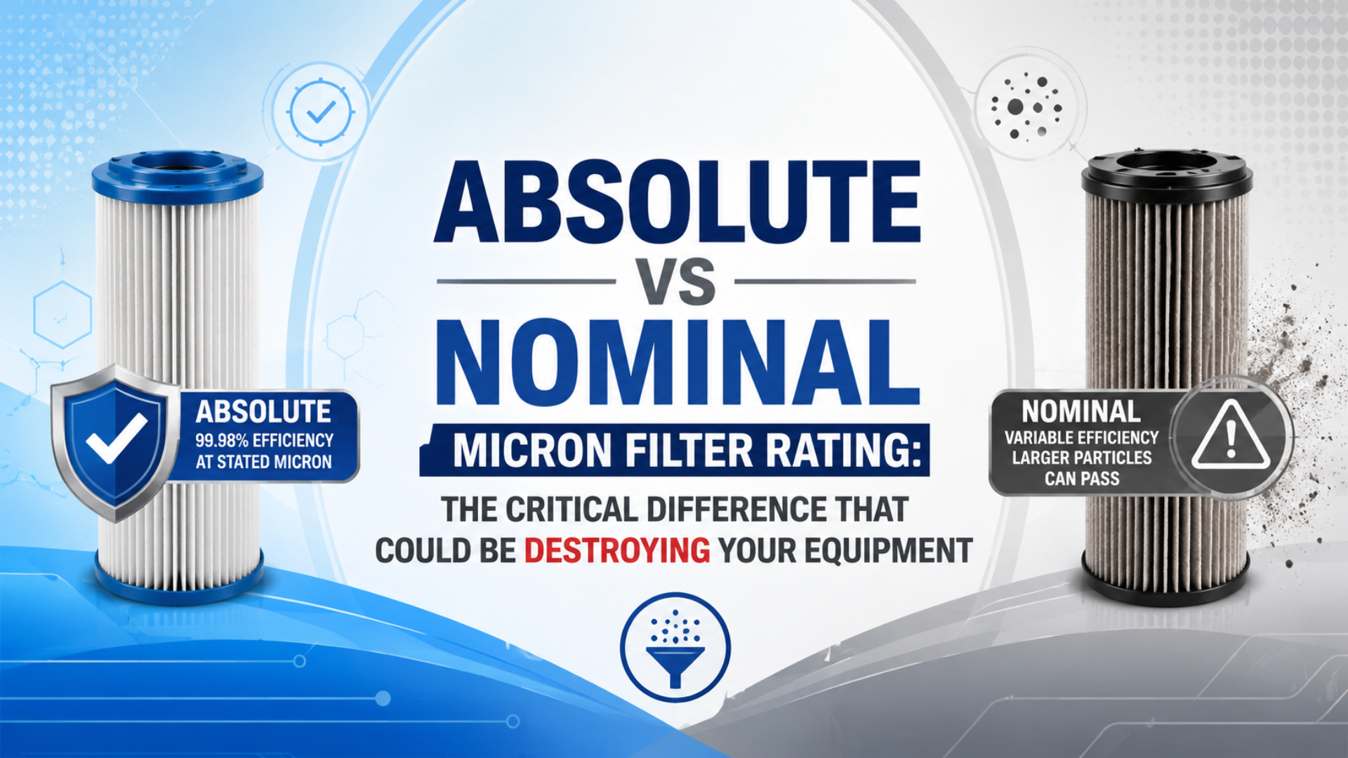
An absolute micron rating and a nominal micron rating are not directly comparable unless the supplier also states the removal efficiency, test method, operating conditions, and pressure-drop data. “Absolute” does not universally mean 99.98%, and “nominal” does not universally mean 85%, 90%, or 95%.
For a pneumatic system, the safer decision is to specify the required air purity at the point of use, then select a compressed-air filter with documented performance under the machine’s actual flow and pressure. A smaller micron number without those conditions can create false confidence, excessive pressure drop, or both.
Key Takeaways
- A micron rating is incomplete without removal efficiency.
- SMC lists nominal ratings from 1 µm at 99% to 0.01 µm at 99.9% (SMC).
- ISO 12500-3 covers compressed-air particulate filter testing; ISO 8573 covers air purity and measurement.
- Check rated flow, pressure drop, drain design, and end-of-life conditions.
What Is the Difference Between Absolute and Nominal Micron Ratings?
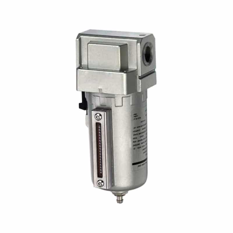
SMC publishes nominal compressed-air filter ratings ranging from 1 µm at 99% efficiency to 0.01 µm at 99.9%, each tied to a particular filter stage and operating data (SMC AFF/AM/AMD30, accessed 2026). That documented range shows why “nominal” alone is not an efficiency value.
A nominal rating is a supplier-defined particle-removal claim at a stated size. An absolute rating is intended to describe a much more restrictive cut-off or retention point. The problem is that neither word supplies a universal efficiency threshold across every filter medium, industry, or test method.
The rating becomes useful only when it is written as a complete performance statement. For example:
Particle size: 1 µm
Removal efficiency at that size: 99%
Test method: stated by the supplier
Rated flow: 750 L/min (ANR)
Inlet pressure: 0.7 MPa
Initial pressure drop: taken from the published flow curve
SMC illustrates why the extra fields matter. Its AFF/AM/AMD compressed-air preparation data lists nominal ratings of 1 µm at 99%, 0.1 µm at 99%, and 0.01 µm at 99.9%. The same document states a rated flow of 750 L/min (ANR) at 0.7 MPa and provides separate flow-versus-pressure-drop curves (SMC AFF/AM/AMD30, accessed 2026). The word “nominal” therefore does not mean one fixed efficiency, even within pneumatic filtration.
A micron number is not a complete filter specification. It tells you the particle size under discussion, but not how many particles at that size pass through, how the filter was challenged, or whether the result remains valid at your peak flow.
| Catalog statement | What it tells you | What is still missing |
|---|---|---|
| “5 µm filter” | A particle size is associated with the element | Efficiency, test method, flow, pressure, and pressure drop |
| “Nominal 1 µm, 99%” | Size and stated removal efficiency | Test protocol and operating conditions unless separately listed |
| “Absolute 5 µm” | Supplier intends a limiting retention claim | The efficiency threshold and test basis still need confirmation |
| “99.9% at 0.01 µm at rated flow” | A defined size and efficiency under a flow condition | Contaminant type, standard, inlet conditions, and pressure-drop limits |
This is the practical difference: “absolute” may be the stronger claim, but documented test data is stronger than either label.
Why pay for the stronger word if the supplier cannot show the efficiency and test conditions behind it?
Why Is “Absolute Means 99.98%” an Unsafe General Rule?
SMC labels a 0.01 µm, 99.9%-efficient compressed-air filter as nominal, which is enough to disprove any rule that “nominal” always means 85% or 95% (SMC AFF/AM/AMD30, accessed 2026). In the same way, “absolute” cannot be assigned one efficiency without the supplier’s test basis.
Some manufacturers and filtration sectors associate an absolute rating with 99.98% removal or a beta ratio of 5,000. That convention cannot be assumed for every compressed-air filter.
Efficiency is simply the fraction of challenge particles removed at the stated size:
Removal efficiency (%) = (upstream count - downstream count) / upstream count × 100If a valid test reports 100,000 particles upstream and 20 downstream in the same size band, the calculated efficiency is 99.98%. The calculation is sound; the missing question is whether the two counts were obtained using an appropriate, documented test for that filter and fluid.
So what does 99.98% prove by itself? Very little until the particle size, challenge, test method, and operating point are attached to it.
Terms such as nominal and absolute have accumulated different meanings in hydraulic filtration, membrane filtration, general ventilation, process filtration, and compressed air. A definition taken from one sector should not be used as proof in another. Treat 99.98% as a reported result only when the supplier identifies the particle size, test method, challenge conditions, and filter model.
Two filters can both say “5 µm” while protecting a machine very differently. One catalog may mean an element with a supplier-defined nominal pore or retention value. Another may report measured removal efficiency over a particle-size range. A third may publish only a convenient label. The number on the housing does not resolve those differences.
Which Standards Apply to Compressed-Air Particulate Filtration?
ISO 12500-3:2009 is the directly relevant filter-test reference. ISO describes it as a guide for determining solid-particulate removal efficiency by particle size for filters used in compressed-air systems. It identifies a fine-filter range from above 0.01 µm to below 5.0 µm and a coarse range from 5.0 through 40 µm (ISO 12500-3, 2009).
That standard answers a filter-performance question. The ISO 8573 series answers a different set of questions about the air itself:
| Standard | Primary role | How to use it in a pneumatic specification |
|---|---|---|
| ISO 12500-3:2009 | Test solid-particulate removal performance of compressed-air filters | Ask whether the filter’s particle-efficiency data was determined using this or another stated method |
| ISO 8573-1:2010 | Classify compressed-air purity for particles, water, and oil | Define the required downstream air-quality class at the point of use |
| ISO 8573-4:2019 | Sample and measure particle size and number concentration in compressed air | Verify downstream particle concentration and the ISO 8573-1 particle class |
| ISO 6953-2:2024 | Test and present supplier characteristics for pneumatic regulators and filter-regulators | Check flow and other declared characteristics for filter-regulator assemblies |
ISO 8573-1 does not assign an “absolute” or “nominal” grade to the filter element. It classifies the resulting compressed air by particles, water, and oil, independent of where the air is specified or measured (ISO 8573-1, 2010). ISO 8573-4 provides particle sampling and measurement methods suitable for evaluating those particle classes (ISO 8573-4, 2019).
This creates a clear engineering chain:
Required point-of-use purity
        ↓
ISO 8573-1 particle, water, and oil target
        ↓
Filter or filter train selected from documented performance
        ↓
Performance checked at actual inlet pressure and peak flow
        ↓
Downstream purity verified with an appropriate ISO 8573 method
Use the separate guide to ISO air-quality standards for pneumatic systems when the machine specification still says only “clean, dry air.”
Which standard should appear on the purchase order? The one that matches the claim being purchased: filter performance, delivered-air purity, or downstream measurement.
Why Does ISO 16889 Not Prove Pneumatic Filter Performance?
ISO 16889:2022 is titled Hydraulic fluid power — Filters — Multi-pass method for evaluating filtration performance of a filter element. Its scope is hydraulic filter elements exposed to a continuous contaminant-injection, multi-pass test (ISO 16889, 2022). The resulting beta ratio is meaningful inside that hydraulic test framework, not automatically in compressed air.
The standard is associated with a beta ratio:
βx = number of particles ≥ x µm upstream
     / number of particles ≥ x µm downstream

Efficiency = (1 - 1 / βx) × 100%
The arithmetic gives these examples:
| Beta ratio at the stated size | Calculated efficiency |
|---|---|
| β2 | 50% |
| β10 | 90% |
| β100 | 99% |
| β5,000 | 99.98% |
The equation does not make ISO 16889 a compressed-air filter standard. Hydraulic oil and compressed air differ in fluid properties, contaminant behavior, filter construction, and test setup. A beta ratio can be useful when a supplier explicitly publishes it with the applicable method, but it should not be used to manufacture an unsupported “absolute” rating for a pneumatic filter.
ASTM F838 is even further from this application. It evaluates bacterial retention by membrane filters used for liquid filtration under a bacterial challenge (ASTM F838-20). It is not a general test for particulate filters protecting pneumatic valves and cylinders.
How Should You Compare Two Pneumatic Filter Data Sheets?
SMC’s AFF30 data combines four fields that a bare micron label omits: 1 µm nominal filtration, 99% efficiency, 750 L/min (ANR) rated flow, and a 0.7 MPa inlet-pressure condition (SMC AFF/AM/AMD30, accessed 2026). Use that level of disclosure as the comparison baseline.
Start by ignoring the words “absolute” and “nominal” for one minute. Put the measurable fields side by side.
What should happen if a catalog omits one of those fields? Mark it as unknown and ask for the supporting data instead of filling the gap with an industry rule of thumb.
1. Match the Contaminant to the Filter Function
A general-purpose particulate filter, water separator, coalescing filter, adsorption filter, and sterile filter solve different problems. A fine particle rating does not prove that a filter removes water vapor, and a coalescing filter is not a dryer.
If the risk is rust and scale from the distribution pipe, solid-particle performance is central. If the problem is oil aerosol, use a coalescing stage with documented aerosol performance. If pressure dew point is too high, investigate the dryer and distribution conditions rather than installing a finer particulate element. The guide to coalescing filters and compressed-air quality explains that boundary in more detail.
2. Find the Efficiency at the Stated Particle Size
Reject comparisons that pair “5 µm nominal” with “5 µm absolute” but provide no efficiencies. Ask the supplier for a curve or table showing removal efficiency by particle size. If only one efficiency point is available, record exactly what it covers.
Do not infer that a nominal 5 µm filter passes particles three or four times larger. A depth filter can capture some smaller particles and pass some particles near its rating; the distribution depends on its media, loading, velocity, and test method. Only measured performance supports a pass/fail claim.
3. Confirm the Test Method and Reporting Basis
Look for ISO 12500-3 or another clearly described compressed-air particle test. Record the challenge contaminant, particle-size bands, instrument, direction of flow, and whether the result applies to a representative type test or the exact element.
Also check the flow reference. L/min (ANR), NL/min, SCFM, and actual volumetric flow are not interchangeable labels. The catalog should state its reference conditions, especially when flow is converted to a standard atmosphere.
4. Read the Flow-versus-Pressure-Drop Curve
Every filter creates pressure loss, and pressure drop normally rises with flow and element loading. SMC’s FRL technical guide gives an AF30 example in which 2,000 L/min (ANR) at 0.5 MPa inlet pressure corresponds to a 0.04 MPa pressure drop; the same guide tells the reader to select the model from its published flow characteristic rather than from port size alone (SMC FRL Technical Data, accessed 2026).
That is an example for one product and condition, not a universal acceptable drop. For your machine, plot the highest simultaneous demand at the lowest expected inlet pressure. Include the bowl, element, regulator, lubricator if present, fittings, valves, and tubing in the dynamic pressure budget.
The FRL selection guide covers point-of-use flow sizing and maintenance. If actuator speed or force falls only during peak demand, diagnose the complete pneumatic pressure-drop path before blaming the micron rating.
For a focused sizing sequence, also compare the FRL port, flow, and pressure-drop checks against the machine’s simultaneous demand.
5. Define the Dirty-Element Limit
Initial pressure drop describes a clean element. Maintenance needs a second value: the differential pressure or service condition at which the element must be replaced. If the supplier does not state an end-of-life limit, request it rather than inventing one.
Install a differential-pressure indicator or measure pressure on both sides when the application justifies it. Record readings at comparable flow. A high differential pressure at peak production cannot be compared with a low-flow reading during an idle shift.
6. Check Installation and Environmental Limits
Confirm:
- maximum and minimum operating pressure;
- temperature range;
- bowl material compatibility with cleaning chemicals, solvents, and ambient conditions;
- manual, normally open, or normally closed drain behavior;
- orientation and available drain space;
- element part number and service access;
- downstream cleanliness requirements after installation or maintenance.
A technically strong element can still underperform if flow is reversed, the drain cannot discharge, the bowl is chemically attacked, or the element remains in service after its pressure-drop limit.
A Better Filter Comparison Example
SMC’s published nominal filtration efficiencies span 99% to 99.9% across its AFF/AM/AMD30 stages, while the stated flow condition remains 750 L/min (ANR) at 0.7 MPa (SMC AFF/AM/AMD30, accessed 2026). A responsible comparison keeps those fields together.
The following entries are hypothetical. They show how to evaluate catalog evidence without pretending that either filter has been tested.
| Field | Filter A | Filter B | Engineering interpretation |
|---|---|---|---|
| Catalog label | “5 µm nominal” | “5 µm absolute” | Labels alone do not decide |
| Efficiency at 5 µm | Not stated | 99.9% | Filter B gives a value, but its method still matters |
| Test method | Not stated | ISO 12500-3 stated | Filter B has the more auditable claim |
| Rated flow | 1,500 L/min | 1,200 L/min | Neither is acceptable until checked at actual inlet pressure |
| Initial pressure drop | Not stated | Curve supplied | Filter B can be included in the dynamic pressure budget |
| Element-change limit | Not stated | Differential-pressure limit supplied | Filter B supports condition-based maintenance |
| Downstream test | None | ISO 8573-4 sampling planned | Filter B’s result can be verified at the point of use |
Filter B has the better specification, not because its label says “absolute,” but because its claim is measurable and verifiable. Filter A may perform well, but the missing data prevents a defensible comparison.
In our experience reviewing pneumatic applications, the most useful supplier question is not “Is this filter absolute?” We ask: “At the specified particle size, what efficiency can you document at our peak flow and minimum inlet pressure, and what pressure drop should we expect when the element is clean and when it is due for service?” That wording usually exposes whether two apparently similar catalog ratings are actually comparable.
How Do You Select the Right Rating for a Pneumatic Machine?
SMC states that the ISO 8573-1 purity class attainable with its AFF/AM/AMD system will differ with the inlet-air conditions (SMC AFF/AM/AMD30, accessed 2026). Therefore, no filter grade can guarantee the same downstream class in every plant.
There is no universal rule that every pneumatic cylinder needs a 5 µm absolute filter or every high-cycle valve needs a 1 µm filter. Start with the component and process requirements.
Where should the purity be measured? At the point whose contamination risk the specification is meant to control, not simply at the most convenient compressor-room port.
- Identify the protected equipment. Record the valve, cylinder, regulator, instrument, air bearing, nozzle, and any product-contact use.
- Collect the manufacturer’s air requirement. Look for particle, water, oil, pressure, temperature, and lubricant limits for the exact models.
- Write the point-of-use purity target. Use the three-part ISO 8573-1 particle:water:oil format where applicable, and identify the sampling location.
- Measure or characterize the inlet condition. A filter cannot be selected responsibly without knowing the contaminant load, condensate behavior, peak flow, and minimum pressure.
- Choose the treatment train. A water separator, general-purpose particulate filter, coalescing filter, dryer, or adsorption stage may be needed in sequence.
- Check dynamic capacity. Use the supplier’s flow-versus-pressure-drop data at the real operating point, not merely the port size or headline flow.
- Plan drainage and element service. Define inspection frequency, differential-pressure limit, replacement part, and safe isolation procedure.
- Verify downstream air. Sample at the point that matters using an appropriate ISO 8573 method, especially when contamination has already caused failures.
SMC’s AFF/AM/AMD document notes that the attainable ISO 8573-1 class depends on inlet-air conditions. That warning is important: a filter grade does not guarantee a downstream purity class in every system. Dirty piping, saturated drains, filter bypass, excessive flow, and maintenance work can all change what reaches the machine.
If the plant needs help turning the three ISO 8573-1 contaminant groups into measurable acceptance points, use the compressed-air quality management workflow. Treatment decisions should also fit the wider compressed-air system design, not be isolated at one filter bowl.
In our application reviews, we have found that the unresolved field is often the sampling point. A compressor-room result cannot prove what reaches a fast-cycling valve after hundreds of meters of pipe. We therefore record the purity target and test location on the same line of the specification.
What Happens When the Filter Is Too Fine or Too Coarse?
SMC’s AF30 example shows a 0.04 MPa pressure drop at 2,000 L/min (ANR) and 0.5 MPa inlet pressure, even with a correctly selected pneumatic filter (SMC FRL Technical Data, accessed 2026). Finer filtration can raise that loss if the housing or element is undersized or loaded.
A filter with inadequate documented efficiency may allow damaging contamination to continue downstream. Depending on the component and contaminant, the evidence may include scratched sealing surfaces, sticking valve spools, blocked pilot orifices, unstable regulator behavior, accelerated seal wear, or contaminated process air. Diagnose the failed parts and downstream sample rather than assigning every pneumatic failure to one micron number.
An unnecessarily restrictive filter can create a different failure mode. Higher pressure drop can reduce valve flow, slow cylinder motion, lower available force, lengthen cycle time, and encourage operators to raise compressor or regulator pressure. It may also increase element cost and service frequency without improving the air beyond what the component or process requires.
Can the smaller micron number be the worse choice? Yes, when the extra restriction does not serve a documented air-quality requirement.
The correct rating is therefore not the smallest number available. It is the filtration performance that reaches the required air-quality target with acceptable pressure drop, service life, and operating cost.
FAQs About Absolute and Nominal Micron Filter Ratings
ISO 12500-3 identifies two particle-test ranges for compressed-air filters: above 0.01 µm to below 5.0 µm, and 5.0 through 40 µm (ISO 12500-3, 2009). The standard’s size ranges still do not turn “nominal” or “absolute” into universal efficiencies.
These answers use the terminology cautiously because suppliers do not all apply “absolute” and “nominal” in the same way.
Does an absolute micron rating always mean 99.98% efficiency?
No. Some suppliers and filtration sectors use 99.98% or β5,000 as an absolute-rating convention, but there is no safe universal assumption for every compressed-air filter. Require the efficiency, particle size, test method, flow, pressure, and model to be stated together.
Are all nominal 5 µm pneumatic filters equivalent?
No. They may use different media, efficiencies, test methods, rated flows, inlet pressures, and clean-element pressure drops. Compare documented performance and verify the downstream air-quality result instead of purchasing by the 5 µm label alone.
Can beta ratio be used to compare compressed-air filters?
Only when the supplier explicitly states a suitable test method and comparable conditions. ISO 16889 beta ratios come from hydraulic filter testing, so they should not automatically be treated as pneumatic filter ratings. For compressed-air particulate filters, look first for data based on ISO 12500-3 or another clearly documented compressed-air test.
Is a smaller micron rating always better for pneumatic equipment?
No. A finer element can improve particle removal, but it may also increase pressure drop and maintenance demand. Select the rating from the component’s air-quality requirement, contaminant load, peak flow, minimum pressure, and acceptable service interval.
How can I verify that a pneumatic filter is protecting the machine?
Record differential pressure at a repeatable flow, inspect the drain and element, and measure downstream particle concentration at the point of use. ISO 8573-4 provides methods for particle sampling and measurement used to evaluate ISO 8573-1 particle classes. Trend the result over time and after element replacement.
The critical difference is not one word on the data sheet. It is the difference between a vague micron label and a complete, testable performance specification. When efficiency, test method, flow, pressure drop, maintenance limit, and downstream purity agree, the filter becomes an engineered control instead of a hopeful accessory.
External technical references and retrieval dates
- ISO 12500-3:2009: Solid-particulate removal-efficiency testing for filters used in compressed-air systems. Retrieved 2026-07-14.
- ISO 8573-1:2010: Compressed-air purity classes for particles, water, and oil. Retrieved 2026-07-14.
- ISO 8573-4:2019: Compressed-air particle sampling, measurement, and uncertainty guidance. Retrieved 2026-07-14.
- ISO 16889:2022: Hydraulic filter multi-pass testing and filtration-performance evaluation. Retrieved 2026-07-14.
- ISO 6953-2:2024: Test methods and supplier-literature characteristics for pneumatic regulators and filter-regulators. Retrieved 2026-07-14.
- ASTM F838-20: Bacterial-retention testing for membrane filters used in liquid filtration. Retrieved 2026-07-14.
- SMC, Compressed Air Preparation Filter AFF/AM/AMD30: Nominal particle ratings, corresponding efficiencies, rated-flow conditions, and pressure-drop curves. Retrieved 2026-07-14.
- SMC, FRL Technical Data: Air-filter construction and flow-versus-pressure-drop selection example. Retrieved 2026-07-14.