


Gas is matter whose particles move freely enough to fill the available space, so its density changes when pressure, temperature, mass, or volume changes. That makes gas useful for storing and transmitting energy, but it also means a static pressure reading can’t predict an industrial machine’s force, speed, consumption, or response by itself.
Pneumatic automation turns that definition into a practical lesson. Pressure difference creates actuator force. Gas mass flowing through the complete supply and exhaust paths changes chamber pressure over time. Temperature and moisture change density, condensation risk, lubrication, and material limits. Gas identity adds another layer because compressed air, nitrogen, oxygen, and process gases aren’t interchangeable services.
TL;DR: NIST defines 1 standard atmosphere as exactly 101,325 Pa. A 6 bar gauge air line near that reference is therefore about 7.013 bar absolute. Use absolute pressure and kelvin for gas-state calculations, dynamic pressure and flow for machine diagnosis, and gas-specific compatibility and safety requirements before choosing hardware.
What Defines Gas in Engineering Terms?
OpenStax defines an ideal-gas state with absolute pressure, volume, particle count, and absolute temperature, while NIST defines 1 standard atmosphere as exactly 101,325 Pa. Those references show why a gas description is incomplete unless its amount, state variables, units, and reference conditions are declared (OpenStax; NIST).
At the molecular level, gas particles are widely separated compared with the same material in a liquid or solid phase. They move in different directions, collide with each other, and collide with the boundary containing them. Those wall collisions create pressure. Heating raises their average translational kinetic energy, while cooling lowers it. Compressing a fixed gas amount shortens the distance available for motion and increases collision frequency. Because considerable space exists between particles, adding mass or reducing volume can raise gas density much more than it would raise a typical liquid’s density. Molecular volume and attraction become important as density rises or the gas approaches liquefaction (OpenStax).
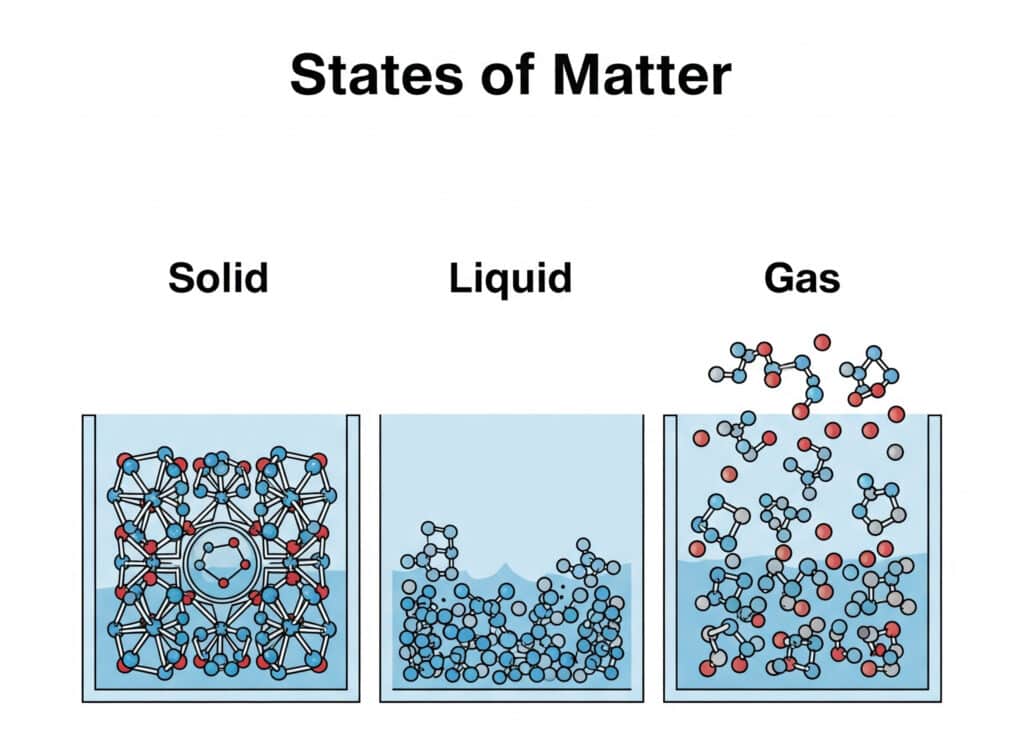
That distinction changes machine behavior:
| Engineering property | Gas | Liquid | Industrial consequence |
|---|---|---|---|
| Shape | Fills the available boundary | Takes the container shape | Both require containment and a defined flow path |
| Volume | Changes strongly with pressure and temperature | Changes relatively little in ordinary hydraulic service | Pneumatic chambers store energy and behave like compliant springs |
| Density | Varies with state | Usually treated as nearly constant | Actual volumetric flow changes along a gas circuit |
| Phase risk | May condense or liquefy under some conditions | May vaporize or cavitate | Temperature, pressure, and composition set the valid model |
Calling gas “compressible” is true but incomplete. What matters at the machine is how much gas mass occupies a known volume, what its absolute pressure and temperature are, and how quickly mass can enter or leave. That is the boundary between a classroom definition and an engineering one.
Which Variables Define a Gas State?
NIST’s 2022 CODATA value of the molar gas constant is exactly 8.314462618 J·mol⁻¹·K⁻¹. In the ideal-gas model, that constant connects absolute pressure, volume, gas amount, and absolute temperature. The equation is compact, but every input still needs a declared unit, reference, and measurement location (NIST).
Its ideal-gas equation is:
Here, is absolute pressure in Pa, is volume in m³, is gas amount in mol, is the molar gas constant in J·mol⁻¹·K⁻¹, and is absolute temperature in K. The model assumes a single gas phase and ideal behavior. It describes a state; it doesn’t by itself predict valve flow or cylinder motion.
Five inputs carry most industrial gas decisions:
| Variable | What must be declared | Typical error |
|---|---|---|
| Pressure | absolute, gauge, or differential; static or dynamic | entering barg or PSIG into an absolute-pressure equation |
| Volume | vessel, tube, manifold, or changing actuator-chamber volume | ignoring fittings, dead volume, or stroke position |
| Temperature | gas temperature in kelvin for state equations | using ambient °C as if it were chamber temperature in K |
| Gas amount | mass or moles inside the selected boundary | treating a leaking or flowing control volume as a fixed mass |
| Composition | dry air, humid air, nitrogen, oxygen, fuel gas, or mixture | borrowing air data for another gas |
Pressure references convert as follows:
is absolute pressure, is the gauge reading relative to local atmosphere, and is local atmospheric pressure. All three must use the same units. NIST defines 1 standard atmosphere as exactly 101,325 Pa, but local atmosphere varies with weather and elevation (NIST).
Need a deeper pressure-reference treatment? Use the separate absolute-pressure guide. It explains when cylinder thrust uses gauge pressure and when gas-state, compressor-ratio, vacuum, or flow calculations require absolute pressure.
How Does Compressibility Change Industrial Equipment?
A 6.0 bar gauge air line referenced to 1.013 bar atmosphere is about 7.013 bar absolute. At equal temperature, composition, and volume, it contains approximately 6.92 times as much gas as the same volume at atmospheric pressure. That calculated ratio explains both the useful energy storage and the delayed pressure response of pneumatic equipment (NIST).
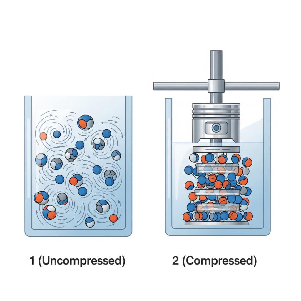
When a valve opens, the actuator chamber does not jump instantly from atmospheric pressure to supply pressure. Gas mass must pass through the filter, regulator, valve, fittings, and tubing while chamber volume may also be changing. A larger chamber or longer tube needs more mass for the same pressure rise. A small restriction slows that transfer, while an obstructed exhaust keeps opposing pressure on the other side of the piston. The same hardware can therefore show one pressure response during a short stroke and another during a long stroke, rapid reversal, or dwell. Supply volume, exhaust volume, heat exchange, and motion all change the pressure history.
This is why force, speed, and stored energy need separate checks. Pressure difference across an effective area creates force:
is available mechanical force in N. The two terms represent chamber pressures in Pa acting on their effective areas in m², and includes seal drag, guide friction, gravity, and other opposing forces. Use synchronized chamber-pressure measurements when dynamic force matters.
Flow determines how quickly those chamber pressures can change. Volume and trapped gas affect compliance, so long tubing and large dead spaces can soften response. Temperature changes density and can move a pressure reading even when no gas crosses the boundary. Those effects explain why a cylinder can pass a static force check yet miss its cycle-time or repeatability target.
Readers who need the dynamic equations, critical-flow boundary, and measurement strategy can continue with the gas-dynamics guide. The present article establishes the variables; that guide develops the moving system.
Why Are Pressure and Flow Different Design Variables?
ISO 6358-1:2013 defines steady-state tests for pneumatic components with compressible-fluid flow paths, while excluding energy-exchanging devices such as cylinders and accumulators. Its 2026 amendment adds measurement-uncertainty evaluation. The scope itself is the lesson: component flow data and actuator motion are related, but they aren’t the same calculation (ISO).
Static gauges can show the expected pressure when a machine is idle because little or no flow is crossing the restriction. During motion, the regulator may droop, a valve path may limit mass flow, or exhaust backpressure may rise. The same gauge can therefore look acceptable before the stroke and miss the condition that causes slow movement.
Pressure supports force. Flow and volume control how quickly useful pressure develops. The system must satisfy both sides:
| Design question | Primary evidence | Misleading shortcut |
|---|---|---|
| Can the actuator move the load? | minimum dynamic chamber-pressure difference and effective area | compressor-room pressure |
| Can it finish the stroke on time? | supply and exhaust conductance, volume, load, and pressure traces | port thread size alone |
| Is a restriction choking? | upstream and downstream absolute pressure plus tested flow data | pressure drop alone |
| Is flow demand stated consistently? | mass flow or volumetric flow at declared reference conditions | unlabeled L/min or CFM |
NIST warns that units such as sccm can use different reference temperatures. Its own table assumes ideal gas at 101,325 Pa and 0°C for the listed standard-volume flow units (NIST). If a supplier uses 20°C, the same numerical “standard flow” label no longer represents exactly the same gas mass.
In our experience reviewing applications, the first productive step is usually to measure pressure at the valve inlet and both cylinder ports during the stroke. Record position at the same time. Three synchronized pressure traces and one position trace reveal far more than a static header gauge. If supply pressure collapses, investigate upstream. If the exhausting chamber stays pressurized, inspect the exhaust path. When both pressures are adequate, the mechanical load or friction deserves attention. Repeat the test under the production event that triggers the symptom, including simultaneous consumers. Otherwise, a quiet-machine test may hide the restriction you are trying to find. The flow-starvation guide develops that troubleshooting branch.
When Does the Ideal-Gas Model Stop Being Enough?
Ideal-gas calculations use a compressibility factor of exactly . NIST REFPROP calculates real-fluid properties including density, phase equilibrium, viscosity, sound speed, and compressibility factor with fluid-specific equations of state. That broader model is appropriate when composition, high pressure, low temperature, or proximity to a phase boundary makes ideal behavior uncertain (NIST REFPROP).
One common real-gas correction is:
is dimensionless. When is close enough to 1 for the required engineering accuracy, the ideal model may be adequate. When it isn’t, use verified gas-property data or a suitable equation of state. “Close enough” belongs to the application uncertainty budget; there is no single pressure threshold that works for every gas and temperature.
Use this boundary:
| Situation | Reasonable starting model | Required next check |
|---|---|---|
| Ordinary dry plant air at moderate pneumatic conditions | ideal-gas relation for state estimates | manufacturer flow data and machine measurements |
| Rapid filling or exhaust | compressible transient behavior | valve conductance, pressure ratio, heat transfer, volume |
| Gas near condensation or liquefaction | real-fluid or two-phase model | phase boundary and supplier property data |
| High-pressure specialty or process gas | gas-specific real-fluid model | exact composition, materials, code, and relief requirements |
| Safety-critical vessel or cylinder | applicable design standard | competent engineering review; never rely on this article alone |
Two shortcuts cause trouble. First, a good ideal-gas state estimate does not validate a valve-flow equation. Second, a value calculated for dry air cannot automatically be transferred to carbon dioxide, hydrogen, refrigerant, oxygen, or a mixed process gas. If the manufacturer publishes gas-specific correction data, use it before applying a generic air curve.
How Do Moisture and Gas Identity Change Component Selection?
ISO 8573-1:2010 classifies compressed-air purity for three principal contaminant groups: particles, water, and oil. It also identifies gaseous and microbiological contaminants. That structure matters because a pressure and flow specification can be correct while moisture, oil aerosol, or particles still shorten valve, seal, sensor, or process life (ISO).
Compressed-air specifications should record the required purity at a named location. A filter rating does not prove the pressure dew point. A dryer rating at nominal conditions does not prove dryness during peak flow. A “lubricated” note does not state how much oil reaches the actuator or whether downstream components permit added oil.
The ISO air-quality guide explains the complete purity notation. When water is the concern, use the pressure-dew-point guide to relate the measured dew point to the coldest surface the air will encounter.
Gas identity changes more than density:
| Gas service | Selection question | Boundary that must not be skipped |
|---|---|---|
| Compressed air | moisture, particles, oil, pressure, and peak flow | point-of-use air quality and exhaust behavior |
| Nitrogen or another inert gas | material compatibility, leakage, ventilation, and flow data | oxygen-displacement risk and site procedures |
| Oxygen or oxygen-enriched service | oxygen-compatible materials and cleanliness | specialist oxygen-service approval; ordinary air hardware is not proof |
| Fuel, toxic, corrosive, or reactive gas | gas-specific valve, seal, detection, and ventilation requirements | applicable code, gas supplier data, and hazard analysis |
| Refrigerant or cryogenic service | phase, temperature, pressure, and relief behavior | real-fluid properties and rated equipment |
This article is not a compressed-gas handling procedure. In the United States, OSHA 29 CFR 1910.101 addresses inspection, handling, storage, utilization, and relief devices for compressed-gas containers (OSHA). Other jurisdictions use different rules. For any gas beyond ordinary plant air, confirm the local legal requirements, gas supplier instructions, and exact component approval before purchase or operation.
Field Measurement Before Component Selection
CAGI reduces compressed-air equipment sizing to three declared parameters: demand in cfm, pressure in psig, and air quality. That is a strong procurement starting point, but an automation circuit also needs time, location, temperature, and load context so the selected components can be checked under the event that drives peak demand (CAGI).
Start by drawing a boundary around the actual path. Include the machine inlet, air preparation, valve, fittings, tubing, actuator chamber, opposite chamber, and exhaust. Then record the following:
- Gas identity and condition: composition, purity, oil policy, pressure dew point, and known contaminants.
- Pressure references: static and dynamic values, gauge or absolute notation, sensor location, and local atmospheric pressure when needed.
- Temperature envelope: supply gas, local ambient, coldest exposed surface, startup, continuous running, and shutdown conditions.
- Demand event: stroke time, simultaneous consumers, peak flow interval, duty cycle, and recovery time.
- Flow path: valve part number and direction, conductance or flow curve, tube internal diameter and length, fittings, silencers, and exhaust restrictions.
- Mechanical result: load, effective area, position trace, speed, acceleration, friction symptoms, cushioning, and repeatability.
What should happen next? Match the evidence to the failure mode. A dynamic inlet-pressure drop points upstream. Persistent exhaust pressure points to the outlet path. Adequate chamber pressure with weak motion points toward area, friction, load, or geometry. Water at the actuator points toward dew point, drainage, cooling, or external ingress rather than a larger valve.
Plant-level decisions need the compressed-air system design guide, which connects demand, storage, distribution, pressure control, and air treatment. For the underlying pressure-area and pressure-volume principles, use the basic pneumatic laws guide.
A testable specification says more than “6 bar air required.” State the gas, reference pressure, minimum dynamic pressure at the component, peak demand and reference condition, temperature range, purity requirement, connection sizes, flow direction, duty cycle, and acceptance test. That gives a supplier enough context to challenge a wrong assumption before hardware reaches the machine.
FAQs About the Basic Concept of Gas
OpenStax, NIST, and ISO separate gas state, reference conditions, component flow data, and air purity into different definitions. These four answers keep that separation intact: use four state variables for the ideal-gas equation, absolute pressure for gas ratios, dynamic measurements for motion, and three ISO 8573 contaminant groups for compressed-air quality.
What is the basic concept of gas?
Gas expands to fill its available boundary and changes density as pressure, temperature, mass, or volume changes. OpenStax relates its ideal state through absolute pressure, volume, particle count, and absolute temperature. Industrial equipment uses those changes for energy storage, transport, purging, heat transfer, sensing, and pneumatic motion (OpenStax).
Why must gas-law calculations use absolute pressure?
Absolute pressure starts at a perfect vacuum, so it represents the physical gas state. Gauge pressure starts at local atmosphere. NIST defines 1 standard atmosphere as exactly 101,325 Pa; therefore, 6 bar gauge near that reference is about 7.013 bar absolute. Mixing the two references corrupts pressure ratios, density, and gas-amount calculations (NIST).
Why can correct pressure still produce a slow pneumatic cylinder?
Static pressure can recover while the machine is idle. During a stroke, restricted supply or exhaust paths may limit gas mass flow and change both chamber pressures. ISO 6358-3 models subsonic and choked compressible flow through systems of components and piping, but a moving cylinder still requires dynamic pressure, position, load, and volume data (ISO).
Is compressed air interchangeable with nitrogen or oxygen?
No. Gas identity changes density, leakage, material compatibility, cleanliness, ventilation, detection, and fire or asphyxiation hazards. OSHA 29 CFR 1910.101 covers compressed-gas containers in the United States, while ISO 8573-1 addresses compressed-air purity. Neither makes ordinary pneumatic hardware automatically suitable for another gas or jurisdiction (OSHA).
Sources and Engineering Boundaries
Source selection uses OpenStax for the molecular model, three NIST references for constants and real-fluid properties, two ISO standards for flow and air purity, and one U.S. OSHA regulation. CAGI adds compressed-air selection context. Product ratings, local law, and gas-supplier requirements still override this general explanation for a specific machine or gas service.
- OpenStax: The Ideal Gas Law, pressure, volume, particle count, and absolute temperature.
- OpenStax: Molecular Model of an Ideal Gas, molecular motion, collisions, and non-ideal behavior.
- NIST CODATA: Molar Gas Constant, 2022 recommended value.
- NIST Guide to SI: Conversion Factors, exact standard-atmosphere conversion.
- NIST: Pressure and Gas Flow Unit Conversions, pressure units and declared standard-flow conditions.
- NIST REFPROP, real-fluid equations of state and transport properties.
- ISO 6358-1:2013, steady-state pneumatic component flow-characteristic testing.
- ISO 6358-3:2014, compressible-flow characteristics of systems of components and piping.
- ISO 8573-1:2010, compressed-air contaminants and purity classes.
- OSHA 29 CFR 1910.101, U.S. compressed-gas general requirements.
- CAGI: Working With Compressed Air, demand, pressure, and air-quality sizing context.
Author David Li focuses his technical reviews on compressed-air safety and system reliability.