

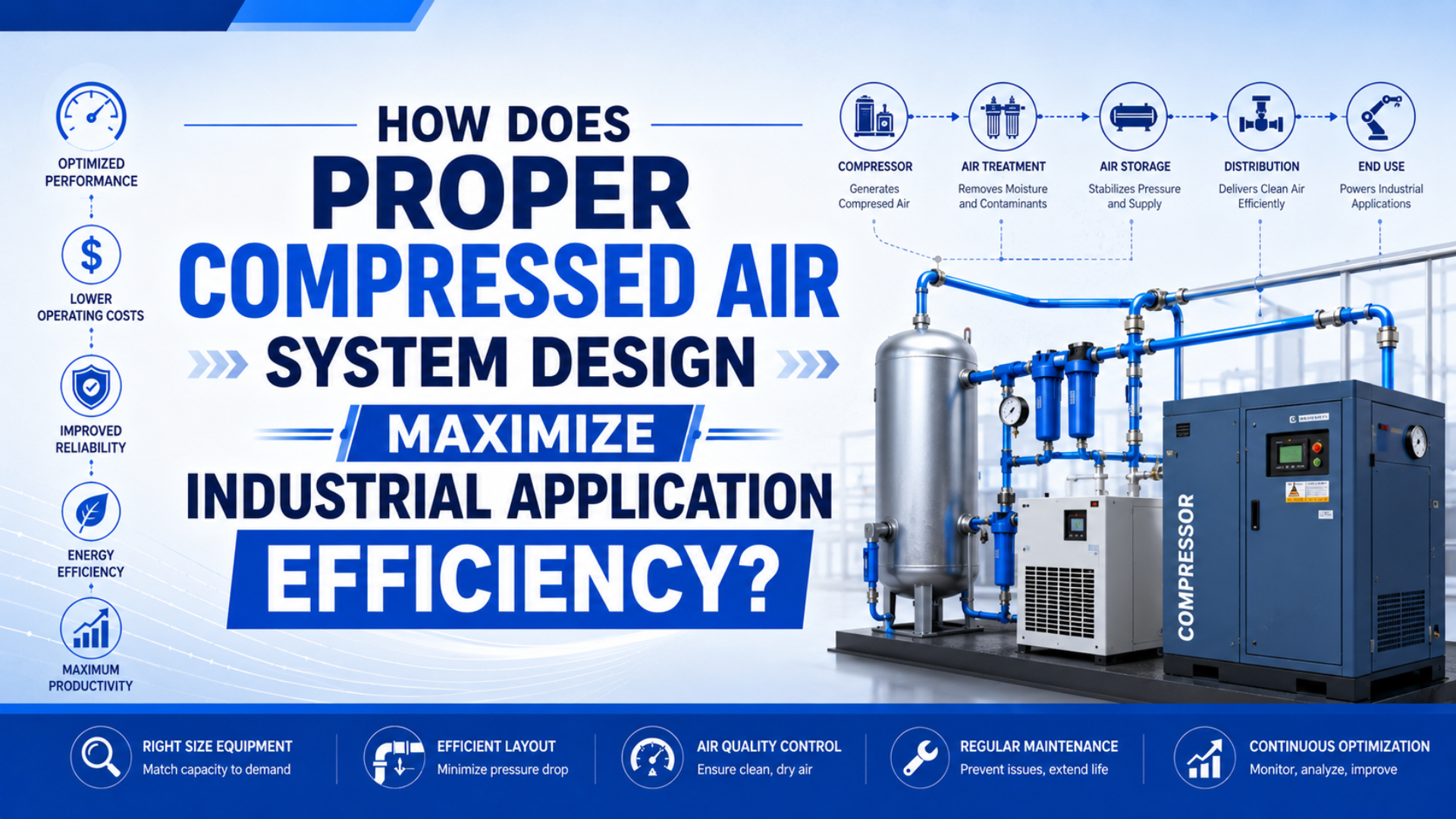
Proper compressed air system design maximizes industrial application efficiency by matching measured air demand, point-of-use pressure, air quality, storage, distribution piping, compressor controls, and maintenance checks before equipment is purchased. CAGI says the three required sizing inputs are demand in cfm, pressure in psig, and air quality (CAGI, 2026).
That sequence matters. A plant can own an efficient compressor and still waste air through leaks, artificial demand, dirty filters, poor branch piping, or an oversized pressure setpoint. A good design does not start with horsepower. It starts with the production job the air must support.
Key Takeaways
- CAGI recommends no more than 10% pressure drop from compressor discharge to any point of use.
- Every 2 psig of excess operating pressure can add about 1% compressor power.
- ISO 8573-1 defines compressed air purity by particles, water, and oil, so air treatment should be specified by class and measuring point.
What Does Proper Compressed Air System Design Mean?
Proper compressed air system design means defining cfm demand, psig pressure, and air quality before selecting compressors, dryers, filters, receivers, regulators, or distribution piping. CAGI identifies those three inputs as the core parameters for compressed-air equipment selection (CAGI, 2026).
In practical terms, the design has to answer five questions:
- What is the maximum, average, and minimum demand profile?
- What pressure must each point of use receive while the machine is working?
- What air quality class is required for particles, water, and oil?
- How will the piping, receiver volume, and controls support peak events?
- How will maintenance verify that the system still performs after installation?
Compressed air system design is the engineering process of converting electrical power into clean, dry, stable, usable pneumatic power at the point of use. It includes compressor selection, storage, treatment, piping, pressure control, measurement, leak control, and end-use review.
The design boundary should extend to the actuator, air knife, tool, valve island, or process nozzle. If the boundary ends at the compressor discharge flange, the design can look efficient on paper while the production line still sees low pressure, wet air, or high operating cost.
How Should You Build the Demand Profile Before Sizing Equipment?
Build the demand profile by measuring maximum, average, and minimum airflow, then adding planned new loads with realistic duty factors. CAGI says an existing system assessment reveals maximum, average, and minimum demand before added cfm can be sized correctly (CAGI, 2026).
Nameplate compressor capacity is not enough. A plant may have enough installed horsepower and still fail during a short clamp, blow-off, or ejector event because the local branch and storage cannot support the burst. The reverse also happens: a plant may buy new capacity when leak repair and pressure correction would have solved the problem.
Demand profile is the measured airflow pattern of a compressed-air system over time: maximum flow, average flow, minimum flow, event duration, and recovery time. It is the data set that separates compressor capacity problems from storage, leakage, and distribution problems.
Use this demand worksheet:
| Demand item | What to measure | Why it matters |
|---|---|---|
| Maximum flow | Peak cfm, SCFM, L/min, or m3/min during the worst production event | Sizes compressor support, receiver volume, and branch flow |
| Average flow | Shift-level demand over real production | Shows energy and compressor loading |
| Minimum flow | Breaks, nights, weekends, idle periods | Reveals leaks and control waste |
| Event duration | Seconds or minutes for each peak | Separates storage problems from capacity problems |
| Recovery time | Time available before the next peak | Determines receiver recovery and duty cycle |
| Future loads | New machines, extra shifts, expansion plans | Prevents redesign after commissioning |
For cylinder-heavy machines, calculate actuator demand separately before rolling it into the plant profile. A group of pneumatic cylinders may average little air over a shift but still need high instantaneous flow during one part of the cycle. Pair the plant demand review with pneumatic flow-rate calculation when actuator timing is the unknown.
In our experience, bad compressed-air sizing usually starts with one missing line in the worksheet: the duration of the peak event. Without that number, teams argue about compressor horsepower when the real issue may be local receiver volume, branch piping, or a short high-flow event.
How Do Pressure Targets Affect Efficiency and Actuator Reliability?
Pressure targets affect efficiency because excess pressure raises power use and leak flow, while low point-of-use pressure weakens actuators. CAGI says every 2 psig of excess operating pressure increases compressor power by about 1%, and well-designed systems should stay within 10% pressure drop (CAGI, 2026).
The correct design pressure is not the highest compressor setpoint the plant can tolerate. It is the lowest stable pressure that lets the most demanding point of use work reliably after piping, dryers, filters, regulators, valves, fittings, and hoses are included.
Pressure budget is the planned pressure allowance from compressor discharge to the working device. It assigns pressure loss to dryers, filters, headers, branch lines, regulators, valves, tubing, and fittings so the final point of use still receives the required pressure under flow.
Use a pressure budget:
| Pressure point | Example check | Design question |
|---|---|---|
| Compressor discharge | Normal and maximum discharge pressure | Is the compressor compensating for downstream loss? |
| Dryer outlet | Pressure after dryer and separators | Is treatment creating hidden pressure penalty? |
| Main header | Minimum pressure during peak flow | Does the distribution system carry the load? |
| Machine inlet | Pressure before local FRL | Does the branch have enough margin? |
| Valve inlet | Pressure while the valve opens | Is the local regulator or filter undersized? |
| Actuator port | Minimum pressure during motion | Does the cylinder see usable working pressure? |
Do not use one static gauge as proof. Static pressure can look fine while a cylinder loses force during the fastest stroke. The related guide on pressure drop in pneumatic systems covers the diagnostic sequence; this article uses that concept as one design budget item.
Which Distribution Layout Keeps Air Stable at the Point of Use?
The best distribution layout keeps velocity, pressure drop, moisture risk, and future expansion under control. CAGI says pressure drop is affected by pipe diameter, internal roughness, air speed, fittings, valves, elbows, and dirty treatment equipment (CAGI, 2026).
For most industrial plants, a looped main header is more forgiving than a long dead-end branch because air can reach a point of use from more than one direction. But the layout still has to match the load map. A loop with small drops, bad quick disconnects, clogged filters, or undersized hoses can still starve the machine.
When you choose the distribution strategy, separate three jobs:
- The main header carries steady plant demand with low pressure drop.
- Local drops and branches supply individual machines without water traps or excessive fittings.
- Point-of-use tubing connects the valve, regulator, and actuator without hiding a flow restriction.
For long runs or high-flow zones, include space for isolation valves, drains, pressure taps, and future drops. A layout that cannot be measured becomes hard to maintain.
How Should Storage and Compressor Controls Be Sized Together?
Storage and compressor controls should be sized together because receiver volume handles short peaks while controls decide which compressor runs at part load. CAGI notes that many systems operate at or near full capacity only 36% to 60% of the week, so part-load behavior matters (CAGI, 2026).
An air receiver does not fix every capacity problem. It helps when the demand event is short and the compressor has enough time to recover before the next event. If average demand exceeds available compressor output, the receiver only delays the pressure failure.
Use this split:
| Design element | Best use | Poor use |
|---|---|---|
| Primary compressor capacity | Repeated average plant demand | Covering every short peak without storage |
| Receiver volume | Short intermittent demand and pressure sag | Masking a permanently undersized compressor |
| VSD or trim compressor | Variable demand profiles | Base load that never changes |
| Sequencer or controller | Multiple compressors and shifting demand | Fixing leaks or oversized pressure targets |
| Local receiver | One high-flow machine or zone | Compensating for a bad main header |
CAGI states that VSD compressors can provide up to a 35% reduction in energy costs and estimates that VSD drives are suitable for about 70% of compressor applications, while only about half of suitable applications have VSD compressors installed (CAGI, 2026). That is not a reason to specify VSD automatically. It is a reason to measure the demand profile before choosing fixed-speed, VSD, sequencing, storage, or a hybrid package.
For short peak events, use the related guide on pneumatic accumulator sizing. For compressor reserve, check duty cycle and recovery time before treating a receiver as free capacity.
How Does Air Treatment Fit the Design Instead of Becoming an Afterthought?
Air treatment should be specified from the required point-of-use air quality, not from a generic filter package. ISO 8573-1:2010 specifies compressed-air purity classes for particles, water, and oil, independent of where air is specified or measured in the system (ISO, 2010).
This makes the design task concrete. Write the air-quality requirement as a location plus a class target, then select dryers, filters, drains, regulators, and monitoring around that target. “Clean dry air” is not a design requirement. It is a wish.
Use this treatment map:
| Requirement | Main equipment | Design warning |
|---|---|---|
| Particle control | Particulate filters, point-of-use filters | Dirty pipework can load elements quickly |
| Liquid water control | Aftercooler, receiver, drains, separators | Manual drains often fail in real service |
| Water vapor control | Refrigerated, membrane, or desiccant dryer | A filter does not set pressure dew point |
| Oil aerosol control | Coalescing filter | Protect fine elements with upstream filtration |
| Oil vapor or odor control | Activated carbon or adsorption stage | Use only where the process requires it |
| Local pressure control | Filter-regulator or FRL unit | Check flow rating under peak demand |
The existing guide on ISO air quality standards covers class selection in detail. The pressure dew point guide covers dryer decisions. In this article, the point is simpler: air treatment is part of the design budget because dryers and filters add pressure drop and maintenance load.
Which Efficiency Fixes Should Come Before Buying More Compressor Capacity?
Leak repair, pressure reduction, inappropriate-use removal, and pressure-drop correction should come before buying more compressor capacity. CAGI says about 80% of air leaks are not audible, and a conservative estimate puts average leak rate in U.S. manufacturing facilities as high as 30% (CAGI, 2026).
That is why “add another compressor” is often the wrong first move. If the plant is leaking, overpressurized, or using open blowoff for cooling and cleanup, new capacity feeds waste first. The production problem may improve for a while, but operating cost rises.
Prioritize the fixes in this order:
- Measure demand, pressure, and power over real production.
- Repair leaks and verify flow reduction after repair.
- Remove inappropriate uses such as open blowing where another method works.
- Lower pressure carefully after proving point-of-use margin.
- Reduce pressure drop through filters, dryers, fittings, pipe, tubing, and regulators.
- Add or relocate receiver volume for short peaks.
- Recheck compressor controls, sequencing, and part-load efficiency.
- Add compressor capacity only after demand reduction and storage checks are complete.
In our project reviews, the fastest sign of a weak design is a compressor upgrade request with no pressure trend, no leak estimate, and no point-of-use measurement. We found that teams often know the compressor horsepower but cannot name the lowest pressure seen at the machine during the fault cycle. Our team has also measured systems where the compressor room looked stable while one valve island lost pressure only during a two-second peak.
What Acceptance Tests Prove the Design Works?
Acceptance tests should prove that the system meets point-of-use pressure, flow, air quality, and energy targets during production. DOE’s sourcebook reports that 35% of surveyed customers had unscheduled compressed-air shutdowns in the previous 12 months, and two-thirds reported potentially serious operating problems (DOE Sourcebook, 2016).
Do not accept a compressed-air design only because the compressor starts, the header reaches set pressure, and the dryer display looks normal. Test the system during the work it was designed to support.
Minimum acceptance data should include:
- Compressor kW, loaded hours, unloaded hours, and control state.
- Header pressure and point-of-use pressure during the highest demand event.
- Flow trend for at least a representative production window.
- Differential pressure across dryers, filters, regulators, and major point-of-use components.
- Dryer pressure dew point or required moisture metric.
- ISO 8573-1 air-quality confirmation when the application requires a written class.
- Leak survey results and verified post-repair reduction.
- Machine cycle time, cylinder speed, clamp force, or process result tied to air performance.
If the acceptance test fails, resist the urge to raise compressor pressure first. Find the mismatch between the design worksheet and the measured system.
What Data Should an RFQ Include?
A compressed-air system RFQ should include demand profile, pressure target, air quality, distribution layout, storage needs, controls, installation constraints, and acceptance tests. CAGI’s cfm, psig, and air-quality triad is the minimum input set, not the full engineering package (CAGI, 2026).
Send this data before asking for a compressor quote:
| RFQ item | Good input | Why it matters |
|---|---|---|
| Facility and process | Line type, shifts, duty cycle, growth plan | Defines operating pattern |
| Demand profile | max, average, minimum cfm with timestamps | Prevents sizing from nameplate guesses |
| Pressure target | required point-of-use pressure during operation | Avoids oversizing discharge pressure |
| Air quality | ISO 8573-1 class or process requirement | Selects dryer, filters, drains, monitoring |
| Layout | compressor room, header, drops, machine locations | Sizes distribution and receiver placement |
| Storage | existing receiver volume and pressure band | Separates short peaks from average demand |
| Controls | fixed-speed, VSD, sequencer, unloading strategy | Determines part-load efficiency |
| Maintenance | drains, filter indicators, leak program | Keeps performance from drifting |
| Acceptance tests | pressure, flow, kW, dew point, leak checks | Converts the quote into measurable results |
For pneumatic automation projects, add downstream component data: valve type, FRL units, cylinder bore, stroke, cycle rate, tube length, and the highest-flow machine step. If the system supports rodless cylinders, include carriage load, target speed, and valve location because long runs and undersized valves can turn a plant-air design issue into a motion problem.
Conclusion
Proper compressed air system design maximizes efficiency by making air demand, pressure, quality, storage, distribution, controls, and maintenance measurable. CAGI’s rules are a good guardrail: define cfm, psig, and air quality before equipment selection, keep pressure drop within 10%, and avoid excess pressure that adds compressor power (CAGI, 2026).
The useful question is not “How large should the compressor be?” The useful question is “What air must the point of use receive during the work cycle, and what design proves it?” Answer that, and the compressor room becomes one part of a controlled pneumatic system instead of the place where every symptom gets blamed.
FAQ
How do I calculate the correct compressor size for my facility?
Measure maximum, average, and minimum demand over real production, then add confirmed new loads with duty factors. CAGI says an existing system assessment should reveal maximum, average, and minimum demand before added cfm is sized. Use receiver pump-up tests and flow logging instead of nameplate guesses.
What pressure drop is acceptable in a compressed air system?
CAGI recommends no more than 10% pressure drop between compressor discharge and any point of use. It also says every 2 psig of excess operating pressure increases compressor power by about 1%. Measure pressure under flow, not only when the system is idle.
Should I use a looped distribution system or point-of-use compressors?
Use a looped main header when many users share plant air and pressure stability matters across zones. Consider point-of-use or decentralized supply only when the load is isolated, high demand, or unusually sensitive. The final decision depends on demand profile, pressure target, maintenance access, air quality, and expansion plans.
When does a variable speed compressor make sense?
A variable speed compressor makes sense when demand changes enough for part-load operation to matter. CAGI says VSD compressors can provide up to 35% energy-cost reduction and estimates that about 70% of compressor applications are suitable. Confirm suitability with measured demand, not by choosing VSD as a default.
How often should a compressed air system be audited?
Audit after major production changes, added equipment, pressure complaints, dryer changes, or compressor-control changes. DOE’s sourcebook reports that only 17% of surveyed customers had conducted a compressed-air system audit over the previous 7 years, while many had serious operating problems. Periodic measurement is better than emergency troubleshooting.
What air quality standard should I use for system design?
Use ISO 8573-1 when the design needs a written compressed-air purity target. ISO says the standard classifies compressed air by particles, water, and oil, independent of the point where air is specified or measured. State the class and the measuring point near the machine or process.
Sources
Use the source list below to check pressure drop, pressure fluctuation, accumulator sizing, ISO air quality, and energy-efficiency claims before applying the design rules to a real plant-air system.
- CAGI, Working with Compressed Air
- U.S. Department of Energy, Compressed Air Systems
- DOE and Compressed Air Challenge, Improving Compressed Air System Performance: A Sourcebook for Industry, Third Edition
- ISO 8573-1:2010, Compressed air - Contaminants and purity classes
- AutomationDirect, Air Prep Basics: How FRLs Clean and Control Compressed Air