

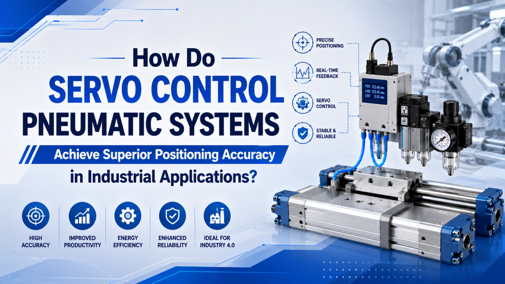
Servo control pneumatic systems are closed-loop pneumatic motion axes that use a valve command, position feedback, and controller correction to move a cylinder or carriage toward a measured target. A proportional directional valve meters air while the controller corrects for load, friction, tube volume, and pressure changes.
The honest answer is more useful than the usual sales claim. Servo pneumatics can make a cylinder far more controllable than a basic on/off valve circuit, but it does not turn compressed air into an electric ball-screw servo. Air is compressible. Friction changes. The machine frame still matters.
Key Takeaways
- Festo describes a 5/3-way proportional valve that converts an analog input into a valve opening and can form a precise pneumatic positioning system with an external controller and displacement encoder.
- CAGI says well-designed compressed-air systems normally keep pressure drop to 10% or less from compressor discharge to point of use.
- Servo pneumatics should be specified as a system: actuator, valve, feedback, controller, air preparation, tubing, load, and acceptance test.
In our experience, the expensive mistake is treating “servo pneumatic” as a part number. It is a control architecture. If the cylinder guide is loose, the exhaust path is undersized, or the load changes faster than the controller can correct, the word servo will not rescue the axis.
What Makes Servo Control Essential for Precision Pneumatic Positioning?
Festo describes the MPYE as a 5/3-way proportional valve that converts an analog input signal into a matching valve opening, and says it can be used with an external position controller and displacement encoder to create a precise pneumatic positioning system (Festo Proportional Valves, 2026).
That is the core difference between a basic pneumatic circuit and a servo-controlled pneumatic axis. A standard directional valve usually commands extend, retract, or stop. A servo pneumatic circuit commands a controlled air path, reads what the actuator actually did, then corrects the next command.
For a rodless cylinder or guided slide, that feedback can be more important than the valve brand. The carriage may see changing friction across a long stroke. The payload may shift. Tube volume may delay the pressure response. Without measured position, the PLC only knows what it asked for, not what happened.
The control loop normally has four jobs:
- Measure actual position from a linear encoder, magnetostrictive sensor, LVDT, or other position device.
- Compare actual position with the target position or motion profile.
- Adjust a proportional valve, servo valve, or pressure regulator command.
- Verify that the axis reached the allowed in-position window before the next machine step starts.
When we review servo-pneumatic RFQs, the best projects usually define the tolerance band before they ask for hardware. “Stop within +/-0.5 mm under a 12 kg moving load at 0.8 seconds stroke time” is actionable. “High precision” is not.
Closed-Loop Architecture, Not Just a Better Valve
Enfield describes its S2 cylinder positioning system as a combination of a proportional valve, sensors, and embedded control electronics that lets cylinders stop at unlimited mid-stroke positions, follow profiles, or reduce end slamming (Enfield Technologies S2, 2026).
That wording matters. The product is not sold as “a valve that magically positions a cylinder.” It is a system. The proportional valve changes the air command, the sensor reports motion, and the controller closes the loop. Remove any one of those three pieces and the axis becomes a different machine.
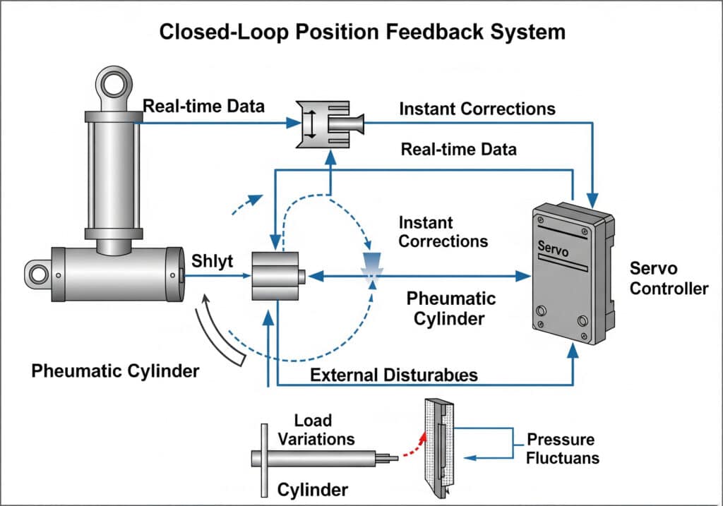
Proportional valves are variable pneumatic control elements that change flow, pressure, or direction in response to an electrical command instead of switching only fully open or fully closed.
For readers comparing this topic with our proportional flow control valve guide, keep the boundary clear. A proportional flow valve controls flow in proportion to a command. A servo pneumatic positioning system uses that variable flow as one actuator inside a larger feedback loop.
This is why a retrofit needs a controls review, not only a parts quote. The PLC may need analog output, high-speed input, networked motion commands, fault bits, and in-position logic. The mechanical side may need better guides, external stops, shock absorbers, or a brake if the load can move after the valve closes.
How Do Feedback Systems Transform Pneumatic Positioning Accuracy?
TE Connectivity says LVDT linear position sensors can measure movement from a few millionths of an inch up to several inches, and some models can measure positions up to +/-30 inches or +/-0.762 meter (TE Connectivity LVDT Tutorial, 2026).
That does not mean every servo pneumatic axis will hold a few millionths of an inch. It means the sensor can provide a measured position signal fine enough for the controller to detect error. The final machine accuracy still depends on mechanics, valve response, air supply, load, tuning, and the acceptance method.
Position feedback means a measured signal from the moving part, not just a timer, valve command, or end-of-stroke switch.
Common feedback choices include:
| Feedback type | Best use | Design concern |
|---|---|---|
| Linear encoder | Higher-resolution carriage position | Needs clean mounting and alignment |
| Magnetostrictive sensor | Absolute position in industrial environments | Must match stroke and package style |
| LVDT | Short to moderate stroke measurement | Needs signal conditioning and installation room |
| Reed or solid-state switches | End or zone confirmation | Not enough for continuous position control |
| Pressure sensors | Force or chamber-state feedback | Pressure is not the same as position |
The strongest systems usually separate sensor resolution from process accuracy. A fine sensor can report position precisely while the axis still misses the part if the guide flexes, the load rocks, or the fixture datum is wrong. Define the measured output before selecting the sensor.
Why Do Standard Pneumatic Systems Drift in Precision Applications?
CAGI states that all compressed-air systems exhibit pressure drop, and that most well-designed systems have no more than 10% pressure drop between compressor discharge and any point of use (CAGI Pressure Drop Technical Brief, 2022).
That 10% guideline explains many “bad cylinder” complaints. A basic pneumatic circuit is often open loop. It assumes the pressure, flow, friction, load, and stop condition will stay close enough from cycle to cycle. When those inputs move, the position and timing move with them.
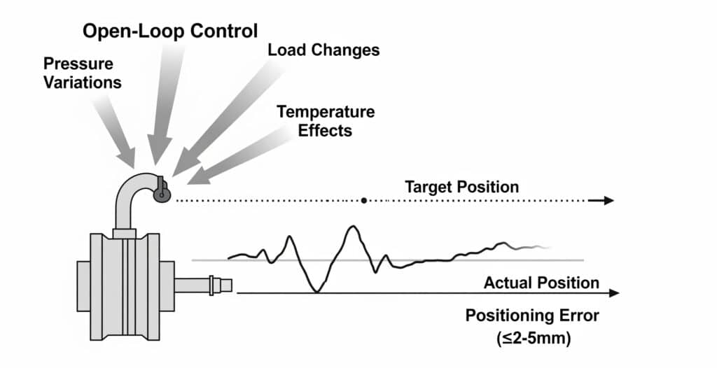
Standard pneumatics can repeat very well against a hard stop. They struggle when the task needs a controlled intermediate position, a moving speed profile, or a recipe-specific stop that changes by product. In those jobs, end sensors only confirm arrival after the fact. They do not correct the path.
Check these items before you blame the valve:
- Point-of-use pressure during motion, not only static regulator pressure.
- Tube length, tube inside diameter, fittings, mufflers, and manifold restrictions.
- Seal friction and guide condition across the full stroke.
- Payload mass, side load, orientation, and center of gravity.
- Cushion setting, external stops, and rebound at the target.
- PLC scan time, analog output update rate, and in-position window logic.
If the problem is mostly end impact or inconsistent speed, start with our flow control valve overview. If the problem is many repeatable mid-stroke positions, compare servo pneumatics with the cylinder versus electric actuator precision guide.
Which Servo Technologies Should You Specify?
Festo lists proportional pressure regulators with analog voltage or current setpoints, including 0-10 V or 4-20 mA, while Burkert describes Type 8605 electronics for electromagnetic proportional valves using PWM output (Festo Proportional Valves, 2026; Burkert Type 8605, 2026).
Those signal details are not catalog trivia. They decide whether your controller can command the valve cleanly. A PLC with only digital outputs cannot drive a proportional valve without extra electronics. A motion controller may need voltage, current, PWM, or fieldbus compatibility depending on the selected hardware.
Specify the control package in layers:
| Layer | What to define | Why it matters |
|---|---|---|
| Actuator | Bore, stroke, guide, mounting, load direction | Mechanics set the physical repeatability limit |
| Valve | Directional function, flow capacity, response, command signal | The controller can only correct through the valve |
| Feedback | Sensor type, stroke range, resolution, mounting | Position data must represent the moving part |
| Controller | Update rate, tuning method, profile support, I/O | Bad tuning can make a good axis unstable |
| Air system | Pressure, filtration, drying, tube size, exhaust path | Compressible air and restrictions shape the response |
| Acceptance test | Load, speed, temperature, cycles, allowed error | Accuracy claims are meaningless without test conditions |
The best specification avoids one universal accuracy number. It defines an in-position window at the working load and working speed. For many industrial machines, a stable +/-0.5 mm process result is more valuable than an unsupported +/-0.05 mm catalog promise.
Application Fit: When Servo Pneumatics Are Honest and When They Are Not
NIST’s 2010 linear motion metrology paper discusses stages with nanometer-order resolution, tens of millimeters of range, and expected sub-micrometer positioning accuracy and repeatability, while also noting the difficulty of certifying that performance with appropriate measurement uncertainty (NIST Ultra-Precision Linear Motion Metrology, 2010).
That is the useful benchmark. If your requirement is true metrology-grade motion, a servo pneumatic axis is usually not the first choice. If your requirement is controlled industrial positioning with pneumatic force density, fast movement, long stroke, or existing air infrastructure, servo pneumatics can be a practical middle path.
Good candidates include:
- Long-stroke transfer axes that need controlled acceleration and deceleration.
- Guided rodless cylinder applications with a few repeatable intermediate positions.
- Pick-and-place moves where approach speed matters more than micron-level placement.
- Heavy push, lift, or clamp tasks where pneumatic force remains useful.
- Existing pneumatic machines that need better feedback without a full electric-axis redesign.
Weak candidates include:
- Micron-class measuring stages.
- Processes with large unpredictable payload changes and no tuning time.
- Machines with unstable plant air, wet air, or chronic pressure drop.
- Applications where a brake is required but not specified.
- Teams with no controls support for commissioning and fault logic.
The comparison is not “pneumatic versus electric” in the abstract. It is process tolerance, load, stroke, speed, environment, and maintenance skill. The mixed-system article on using cylinders and electric actuators together is useful when only one axis in the station actually needs closed-loop positioning.
What RFQ Data Should You Send Before Asking for Accuracy?
NIST’s 2020 publication on performance evaluation for single-axis linear positioning systems shows why an accuracy request should include the test method, not only the target number (NIST Single Axis Positioning Systems, 2020).
For a servo pneumatic RFQ, send the data that lets the engineer test the loop on paper before quoting parts:
| RFQ item | Example detail |
|---|---|
| Stroke and positions | 600 mm stroke, stops at 0, 240, and 520 mm |
| Tolerance window | +/-0.5 mm at the working load |
| Moving mass | 18 kg carriage plus product |
| Motion target | Extend in 0.9 seconds, slow approach for final 80 mm |
| Mounting | Horizontal, guided externally, side-load direction shown in sketch |
| Air supply | 6 bar regulated, measured at valve inlet during motion |
| Valve interface | 0-10 V, 4-20 mA, PWM, Ethernet, or other |
| Feedback | Encoder, magnetostrictive sensor, LVDT, or existing switches |
| Safety state | Exhaust, hold, brake, or controlled stop after E-stop |
| Current problem | Overshoot, drift, impact, bounce, missed sensor, or slow cycle |
This is also where a basic solenoid valve may still win. If the machine only needs two end positions and a hard stop defines the process result, a closed-loop servo pneumatic package may add cost and commissioning effort without solving a real problem.
For project review, send the above data with drawings, photos, and the intended inspection method through contact. The engineering context on about us explains how Bepto handles pneumatic component matching, but the short version is simple: describe the load path before asking for the part number.
Conclusion
Servo control pneumatic systems achieve superior positioning accuracy by measuring the actuator position, comparing it with the commanded target, and correcting airflow through a proportional control element. The improvement comes from the whole loop: stable compressed air, suitable mechanics, feedback, valve sizing, controller tuning, and a realistic acceptance test.
Treat servo pneumatics as a strong middle option. Use it when a pneumatic axis needs controlled mid-stroke positioning, smoother profiles, or verified in-position logic. Use standard pneumatics for simple two-position motion. Use electric motion when the process needs tightly programmable profiles, high precision, or traceable motion data.
FAQs About Servo Control Pneumatic Systems Positioning Accuracy
The 5 answers below keep the claim bounded: Festo’s 5/3-way proportional valve example, CAGI’s 10% pressure-drop guideline, TE’s LVDT measurement range, and NIST’s measurement-uncertainty guidance all point to the same rule. Specify the system and test condition before accepting an accuracy number.
Are servo pneumatic systems always more accurate than standard pneumatic cylinders?
No. They are more controllable when the axis needs mid-stroke positioning, profile control, or feedback correction. A standard cylinder can still repeat well against a hard stop. Servo pneumatics become valuable when the target is not simply “extend fully” or “retract fully.”
Can I add a proportional valve to get servo positioning?
Not by itself. A proportional valve gives the controller a variable air command, but it does not measure cylinder position. Repeatable servo positioning also needs a target, feedback sensor, controller logic, tuning, and a mechanical installation that can respond consistently.
What position sensor is best for a servo pneumatic cylinder?
It depends on stroke, environment, resolution target, mounting space, and controller interface. Linear encoders fit higher-resolution guided axes. Magnetostrictive sensors are useful for absolute industrial position. LVDTs are common for short to moderate measurement ranges with suitable signal conditioning.
When should I choose an electric actuator instead?
Choose electric motion when the axis needs many programmed positions, synchronized profiles, logged position data, low vibration, or very tight tolerance. Servo pneumatics can be a practical middle option, but compressed air, tubing volume, friction, and pressure variation still limit the loop.
What should I measure during commissioning?
Measure actual position error, repeatability, stroke time, point-of-use pressure during motion, valve command, sensor signal, load condition, and in-position fault rate. Do not validate the axis from static regulator pressure alone. The machine should pass under real load and real cycle timing.
External Technical References
- Festo Proportional Valves, 5/3-way MPYE positioning concept and 0-10 V or 4-20 mA setpoints. Retrieved 2026-07-08.
- Enfield Technologies S2 Cylinder Positioning System, proportional valve, sensors, embedded electronics, mid-stroke stops, and profile control. Retrieved 2026-07-08.
- Enfield Technologies video: S2 Positioning - Better Rodless Cylinder Positioning, external-feedback rodless cylinder demo. Retrieved 2026-07-08.
- TE Connectivity: Understanding LVDTs, LVDT measurement range and output behavior. Retrieved 2026-07-08.
- CAGI Pressure Drop Technical Brief, pressure-drop guidance and point-of-use troubleshooting. Retrieved 2026-07-08.
- NIST: Ultra-Precision Linear Motion Metrology, accuracy, repeatability, and uncertainty context for precision stages. Retrieved 2026-07-08.
- NIST: Development of a New Standard for the Performance Evaluation of Single Axis Linear Positioning Systems, single-axis performance evaluation context. Retrieved 2026-07-08.
- Burkert Type 8605 PWM Control Electronics, electronics for electromagnetic proportional valves. Retrieved 2026-07-08.