

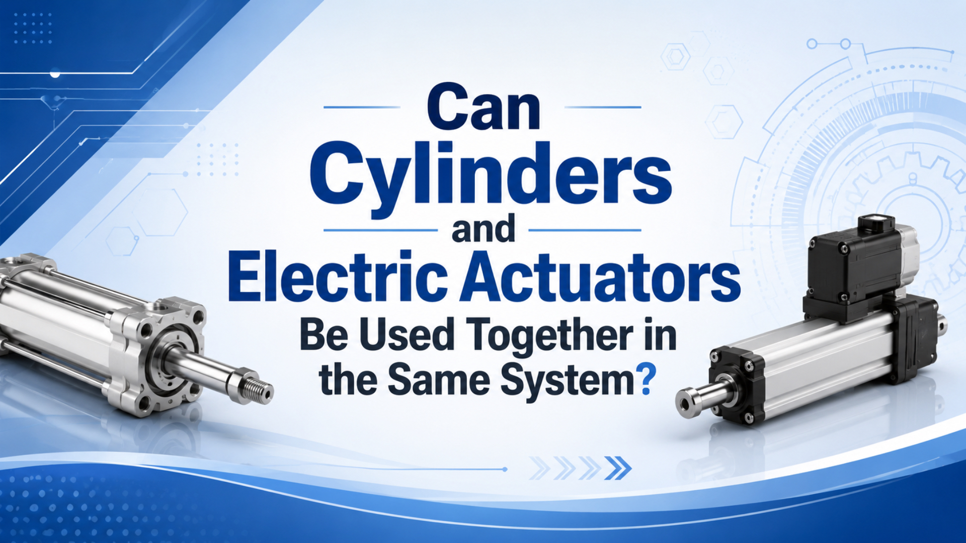
Yes. Pneumatic cylinders and electric actuators can work in the same machine when each axis is assigned by job: force, speed, stroke, position count, duty cycle, environment, and safety state. Festo frames actuator selection around load, precision, dynamics, environment, and life cycle cost, which is exactly why mixed systems make sense (Festo, 2026).
This article is not another broad cylinder vs actuator comparison. It assumes the team already accepts both technologies. The hard work is deciding where air ends, where electric motion begins, and what the PLC must prove before it lets the next motion start.
Key Takeaways
- Use pneumatics for simple high-speed or high-force moves, and electric axes for programmable positions.
- DOE puts compressed-air overall efficiency at 10-15%, so air demand belongs in the system cost check.
- OSHA 1910.147 treats pneumatic and electrical sources as hazardous energy during servicing, so mixed machines need one energy-control plan.
The best hybrid design usually comes from a boring question: “What is the axis paid to do?” If the axis only has two mechanical stops, air may be enough. If the axis changes stroke by recipe, measures force, or follows a profile, electric motion earns its cabinet space.
What Is the Short Answer for a Mixed Actuator System?
A mixed actuator system is valid when pneumatic and electric axes have separate jobs. ISO 15552 covers 1,000 kPa, or 10 bar, pneumatic cylinders with 32-320 mm bores, while AutomationDirect lists 3 electric actuator families: ball screw, lead screw, and belt driven (ISO, 2025; AutomationDirect, 2026).
A simple example is a packaging stop: a pneumatic cylinder lifts a product gate quickly, while an electric actuator adjusts the lane width for each package size. The cylinder does not need 20 stored positions. The electric actuator does not need to absorb every hard stop. Each device avoids the job it is poor at.
The same split works in assembly fixtures. Pneumatics can clamp, eject, lift, or push a part to a hard datum. Electric motion can move a tool, camera, probe, or nest to a stored coordinate. What should you avoid? Asking one technology to act like the other just because it is already on the bill of materials.
When Does a Hybrid Pneumatic-Electric System Make Sense?
Hybrid pneumatic-electric design makes sense when at least two motion jobs have different control needs. Festo lists 5 major decision factors: load, precision, dynamics, environment, and costs, and also notes that pneumatics fit fast end-position work while electric axes fit high precision and flexible variants (Festo, 2026).
Use the mixed approach when the station has one rough motion and one fine motion. A long rodless cylinder can move a tray across a guard door opening. A servo or stepper actuator can then place a probe, nozzle, label head, or camera with recipe-specific offsets.
It also works when one task is force-dominant and the next task is data-dominant. A pneumatic clamp can hold a part against a fixture. An electric actuator can then perform a measured insertion or inspection stroke where position feedback matters. That division keeps the expensive axis where feedback has value.
Avoid the hybrid path when the mixed design only hides poor sizing. If the cylinder is undersized, adding an electric actuator will not fix pressure drop. If the electric actuator is too small, adding a cylinder may create binding, side load, and extra controls. Start with load cases, not wishful hardware.
How Should You Split Motion Between Pneumatic and Electric Axes?
Split motion by requirement: two-position speed and simple force usually point to pneumatics, while variable positions, motion profiles, and repeatable adjustment point to electric. AutomationDirect identifies 3 major electric linear actuator types: ball screw, lead screw, and belt driven, so electric selection also needs load, travel, speed, and accuracy data (AutomationDirect, 2026).
| Motion requirement | Better first look | Why it fits | RFQ detail to send |
|---|---|---|---|
| Fast end-to-end transfer | Pneumatic cylinder | Simple stroke, simple stops, high acceleration | Bore, stroke, load, cycle time, pressure, valve flow |
| Clamp, press, eject, lift | Pneumatic cylinder | Force comes from pressure and effective area | Required force, contact time, fixture geometry |
| Recipe-based position | Electric actuator | Stored positions and motion profiles | Stroke range, speed, accuracy, duty cycle |
| Inspection or probing | Electric actuator | Feedback and smooth motion matter | Position tolerance, force limit, sensor timing |
| Long compact travel | Pneumatic rodless or electric belt axis | Footprint matters more than rod extension | Stroke, moment load, guide method |
From what we’ve seen in application reviews, the wrong split usually shows up as a fuzzy sentence: “the cylinder will move it close and the servo will finish it.” Close to what? How close? Under what load? Say the number before the brackets are drawn.
How Should the Cylinder and Electric Actuator Hand Off Motion?
The handoff should be a defined machine state, not a timer guess. CAGI says well-designed compressed-air systems should have no more than 10% pressure drop between compressor discharge and point of use, so pneumatic-ready confirmation should include pressure at the station, not only PLC output status (CAGI, 2026).
For a coarse-to-fine positioning station, the cylinder should report “extended and settled” before the electric axis starts its fine move. That may mean a reed switch, magnetic sensor, external proximity switch, pressure switch, or load confirmation. A solenoid output alone only proves the valve was commanded.
For a clamp-then-probe station, the electric probe should wait for clamp pressure and part presence. If the probe starts while the part is floating, the actuator may measure fixture movement instead of product geometry. That kind of error is quiet. It passes cycle-time checks and fails quality checks.
A practical handoff checklist looks like this:
| Handoff item | Pneumatic signal | Electric signal | Failure to catch |
|---|---|---|---|
| Part located | cylinder end switch or fixture sensor | axis enabled and homed | Probe hits a moving part |
| Clamp force ready | pressure switch or regulator feedback | motion permission bit | Part shifts during electric move |
| Travel clear | valve state plus guard logic | no following error | Axes fight each other |
| Return complete | retract switch | next profile armed | Product is trapped in fixture |
If speed control is part of the issue, review the valve and exhaust path, not just the cylinder. The companion guide on pneumatic flow control valves is a good internal next step before blaming the electric axis.
What Should the PLC Coordinate Between Air and Electric Motion?
The PLC should coordinate sequence, permission, fault, and recovery states for both technologies. AutomationDirect describes electric actuators for single X, X-Y, or X-Y-Z motion, while OSHA 1910.147 requires energy-control procedures when unexpected startup or stored energy release could injure workers (AutomationDirect, 2026; OSHA, 2026).
Do not let the pneumatic branch live in one mental model and the electric branch in another. In the PLC, both should expose clear states: disabled, homing, ready, moving, in-position, faulted, vented, clamped, unclamped, manual mode, and safe mode. The names can differ by platform. The discipline should not.
The minimum control list is short:
| PLC responsibility | Pneumatic branch | Electric branch |
|---|---|---|
| Start permission | air pressure ok, valve ready, exhaust path clear | drive enabled, homed, no following error |
| Motion proof | extend or retract sensor | in-position bit or encoder window |
| Fault handling | loss of pressure, sensor mismatch, valve timeout | drive fault, overcurrent, position error |
| Manual recovery | jog valve with safe speed and guarded area | jog axis with speed limit and hold-to-run |
| Recipe change | stroke stops, sensors, pressure setting | stored positions, speed, acceleration, force limit |
What about timing? Use timers to detect failure, not to pretend feedback exists. A 600 ms delay may work on a clean machine. It may fail after a filter loads, a tube is rerouted, or a drive acceleration limit is changed. Feedback is dull. Dull is good here.
If the pneumatic side needs cleaner sequencing, start with the valve family and sensor map. A solenoid valve may be enough for two positions, while proportional control or external feedback belongs in a different design conversation.
How Do Energy and Total Cost Change the Decision?
Energy and total cost can change the answer even when the first quote favors pneumatics. DOE says typical compressed-air overall efficiency is 10-15%, while Tolomatic defines TCO as purchase cost plus years of service times yearly operating cost (DOE Sourcebook, 2016; Tolomatic, 2017).
Pneumatics can still be the right answer. A short intermittent clamp running on an existing clean air system may be cheap, simple, and easy to maintain. A high-duty positioning axis that exhausts all day may make the compressor part of the actuator price.
For mixed systems, cost review should happen at the station level. Count the cylinder, valve, fittings, tubing, FRL, silencer, sensors, compressor capacity, pressure drop, and maintenance. Then count the electric actuator, motor, drive, cables, cabinet space, software, tuning time, and spare strategy.
For the pneumatic branch, also check plant air preparation. Dirty or wet air changes seal life and speed consistency. A correctly sized FRL unit and realistic working pressure matter more than a pretty actuator comparison table.
How Should Safety Be Reviewed in a Mixed-Energy Machine?
Safety review should treat air and electricity as two stored-energy systems. OSHA 1910.147 covers servicing and maintenance where unexpected energization, startup, or release of stored energy can injure employees, and it defines energy sources to include electrical, mechanical, hydraulic, pneumatic, chemical, and thermal energy (OSHA, 2026).
That means an E-stop drawing is not enough. Ask what happens to trapped air, suspended loads, vertical electric axes, servo brakes, pressure regulators, and spring-return mechanisms. Some pneumatic circuits exhaust safely. Some hold pressure for a reason. Some vertical axes must brake before venting anything.
A mixed-machine safety review should include:
| Safety item | Pneumatic side | Electric side |
|---|---|---|
| Energy isolation | lockable valve, pressure dump, residual pressure gauge | disconnect, drive STO, verified zero energy |
| Stored energy | trapped air, springs, gravity load | motor regeneration, brake release, gravity load |
| Restart prevention | valve state and sensor reset | drive enable reset and homing rule |
| Manual mode | reduced speed, hold-to-run valve command | speed limit, torque limit, hold-to-run jog |
| Maintenance proof | pressure at zero where required | drive disabled and axis secured |
Keep one rule close: do not use software permission as a substitute for energy isolation during maintenance. A PLC bit can be correct and still not make a trapped pneumatic chamber safe. A servo disabled bit can be correct and still not hold a vertical load after a brake fault.
Which Applications Fit Hybrid Actuator Design Best?
Hybrid actuator design fits applications that combine simple force or transfer with programmable adjustment. Festo says pneumatics suit fast repetitive end-position moves, while AutomationDirect lists 5 electric-actuator selection inputs: load, travel distance, intermediate stops, speed, and accuracy (Festo, 2026; AutomationDirect, 2026).
Good candidates usually have one fixed motion and one variable motion:
| Application | Pneumatic job | Electric job | Why hybrid fits |
|---|---|---|---|
| Packaging changeover | gate, stop, diverter, reject push | lane width, label head, camera position | Fast motion plus stored recipes |
| Assembly fixture | clamp, eject, nest lift | insertion, probing, screwdriving position | Force plus feedback |
| Test station | load part, close fixture | move sensor or probe | Repeatable measurement path |
| Material handling | transfer, lift, push | adjustable stop or multi-position slide | Simple motion plus product variety |
| Vision inspection | present part to camera | focus, height, or offset adjustment | Low-force programmable positioning |
For long travel, compare rodless actuator choices before you commit. A pneumatic rodless cylinder may win on compact transfer. An electric belt axis may win when the same stroke needs many stored positions.
For cycle-time reviews, check whether air flow is limiting the pneumatic move. The article on calculating pneumatic flow rate can help separate a valve-flow problem from an actuator-technology problem.
What Should Go Into the RFQ Checklist?
A good RFQ should make the technology split testable. ISO 15552 defines 10 bar pneumatic-cylinder dimensions, AutomationDirect lists electric actuator inputs such as load and travel, and Tolomatic’s TCO formula counts operating cost over years (ISO, 2025; AutomationDirect, 2026; Tolomatic, 2017).
Send these details before asking for a hybrid pneumatic-electric quote:
| RFQ item | Why it matters |
|---|---|
| Process sketch with axes marked | Shows which motion is pneumatic, electric, or shared |
| Load mass and center of gravity | Prevents side-load and moment errors |
| Stroke, usable travel, and hard stops | Separates cylinder travel from electric positioning range |
| Required force and contact time | Sets bore, pressure, thrust, and safety factor |
| Cycle time and duty cycle | Exposes air demand, heat, drive sizing, and wear |
| Number of positions or recipes | Decides whether an electric axis is justified |
| Available pressure and measured point-of-use pressure | Protects against undersized air supply |
| Accuracy and repeatability target | Keeps precision claims measurable |
| Safety state after E-stop and power loss | Prevents trapped-air and gravity-load surprises |
| Maintenance access and spare strategy | Affects total cost after installation |
Do not send only a cylinder part number and ask whether an electric actuator should be added. That is a parts question. A mixed system is a motion question. The supplier needs the state sequence, load case, and acceptance test.
A useful acceptance test is simple: write the sequence as “given, when, then” statements before commissioning. Given clamp pressure is above the setpoint, when the electric probe receives move permission, then the probe must reach position without part-shift alarm. If that sentence cannot be written, the handoff is not designed yet.
FAQs About Hybrid Pneumatic-Electric Actuator Systems
These questions focus on the design boundary, not the generic cylinder definition. For broader actuator selection context, use the cylinder-vs-actuator article; this page stays focused on handoff, cost, safety, RFQ data, and sourced checks for mixed pneumatic-electric stations (Bepto Pneumatic, 2026).
Can pneumatic cylinders and electric actuators run from the same PLC?
Yes. The PLC can command valves, read cylinder sensors, enable drives, select electric motion profiles, and manage faults. The important part is state design. The PLC should prove air pressure, cylinder position, drive ready, homing status, and safety permission before allowing the next motion.
Should the pneumatic cylinder move before the electric actuator?
Usually, but not always. Coarse-to-fine systems often move the cylinder first, then let the electric actuator handle positioning. A clamp-and-probe station may clamp with air first. In other machines, an electric axis may position a nest before a pneumatic cylinder pushes or locks the part.
Are hybrid systems cheaper than all-electric systems?
Only sometimes. Pneumatic hardware can have a lower purchase price, but DOE says compressed air is often only 10-15% efficient, and Tolomatic’s TCO method counts yearly operating cost, maintenance, scrap, and downtime. Compare the whole station over service life, not the actuator invoice alone.
What is the biggest design mistake in mixed actuator systems?
The biggest mistake is using timing as proof. A timer cannot confirm clamp force, part location, drive readiness, or safe venting. Use sensors, pressure checks, in-position windows, and fault states. Timers should detect a late event, not replace feedback.
When should I avoid mixing pneumatic and electric actuators?
Avoid mixing them when the added interface is harder than the original problem. If one electric axis can handle every required position and force cleanly, use it. If one pneumatic circuit can handle a simple two-position task safely, use it. Hybrid is best when the split removes complexity.
Sources and Further Reading
Do not use generic 30-50% savings or 20-40% cycle-time claims without project data. The source list below supports pressure limits, selection criteria, actuator construction, air efficiency, pressure drop, TCO, and hazardous-energy control, starting with ISO 15552 and Festo.
- ISO 15552:2018, pneumatic cylinders with detachable mountings, 1,000 kPa or 10 bar series, 32-320 mm bores. Retrieved 2026-06-04.
- Festo: Pneumatics or electrics?, actuator selection criteria and pneumatic/electric application fit. Retrieved 2026-06-04.
- AutomationDirect: What are Electrical Actuators?, electric linear actuator selection and ball screw, lead screw, and belt families. Retrieved 2026-06-04.
- AutomationDirect video: Linear Motion Products, electric linear slides and actuator visual reference. Retrieved 2026-06-04.
- DOE Sourcebook: Improving Compressed Air System Performance, compressed-air efficiency and economics guidance. Retrieved 2026-06-04.
- CAGI Pressure Drop Technical Brief, pressure-drop target for well-designed compressed-air systems. Retrieved 2026-06-04.
- Tolomatic: TCO, pneumatic vs electric linear actuators, total cost of ownership framing. Retrieved 2026-06-04.
- OSHA 1910.147, control of hazardous energy for servicing and maintenance. Retrieved 2026-06-04.