

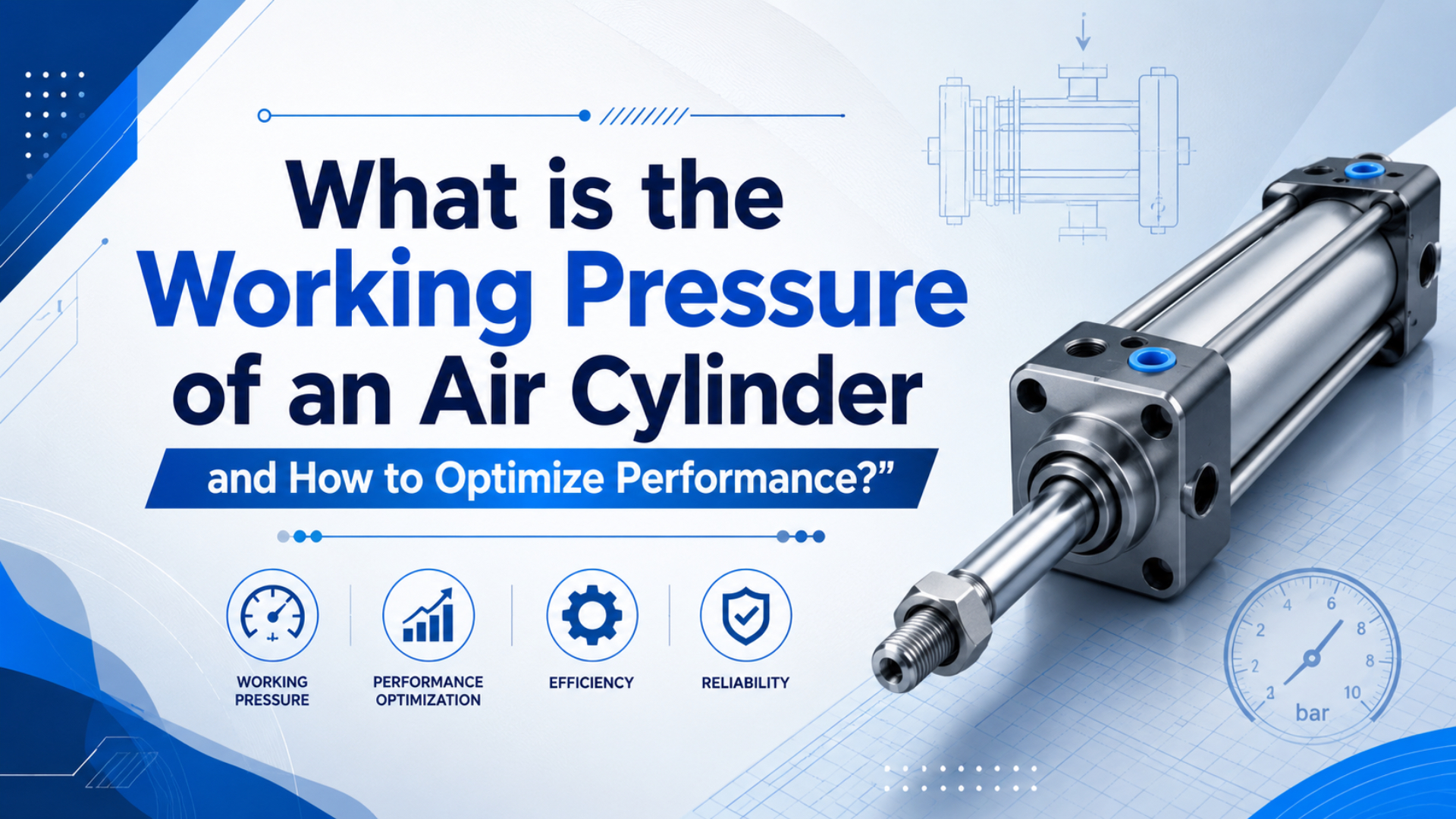
Most industrial air cylinders work best when the pressure is high enough to meet the force requirement, but not so high that it hides sizing, flow, or regulator problems. For many factory cylinders, that means roughly 80-145 PSI, with 100 PSI used as a common calculation point. Always check the cylinder’s own rating first.
Measure under motion. Static gauges hide half the story.
SMC’s MB1 standard air cylinder lists a 0.05 MPa minimum operating pressure, a 1.0 MPa maximum operating pressure, and a 1.5 MPa proof pressure (SMC MB1 catalog, 2025). That range is the better anchor than a generic “more pressure is better” habit.
Key Takeaways
- Standard shop settings often sit near 80-100 PSI, but many cataloged industrial cylinders must stay at or below 1.0 MPa, about 145 PSI.
- DOE says a 2 PSI pressure increase near 100 psig can add about 1.6-2% energy use when unregulated demand is 30-50%.
- Calculate pressure from force and bore area, then fix pressure drop before raising the compressor.
What Are Standard Working Pressure Ranges for Air Cylinders?
Standard air cylinder working pressure is usually selected inside the cylinder catalog limit, not from the compressor nameplate. SMC’s MB1 cylinder gives 0.05-1.0 MPa as its operating range and 1.5 MPa as proof pressure (SMC MB1 catalog, 2025). In inch-pound terms, that is roughly 7-145 PSI operating pressure.
For general manufacturing, engineers often start calculations at 80-100 PSI because many plant headers and pneumatic tools are built around that zone. The final setpoint can be lower for light loads, higher for compact cylinders with real force demand, or capped by the weakest rated component in the local circuit.
Do not use 150 PSI as a reflex target. If the cylinder, valve, tube, fitting, regulator, or sensor has a lower working-pressure rating, that lower rating controls the circuit. From what we’ve seen, many “weak cylinder” complaints are actually undersized tubing, a clogged filter, or a regulator that cannot flow enough air during the stroke.
| Pressure band | Approximate range | Where it fits | Engineering note |
|---|---|---|---|
| Low pressure | 30-60 PSI | Light positioning, small clamps, low-force indexing | Good when bore area is generous and speed is modest. |
| Common industrial setting | 80-100 PSI | General pneumatic cylinders and machine actuators | Often the first calculation zone, not a universal requirement. |
| Upper standard range | 100-145 PSI | Higher force from limited bore size | Check catalog maximum pressure and component ratings. |
| Above standard pneumatic range | Above 145 PSI | Special-purpose equipment only | Use only when every component is rated for it. |
The useful question is not “what pressure can the cylinder take?” It is “what is the lowest point-of-use pressure that still moves the load at the required speed with margin?” That wording keeps you from solving a local flow problem by raising the entire plant pressure.
How Do You Calculate Optimal Working Pressure for Your Application?
Calculate cylinder pressure from required force, bore area, direction, and a margin for friction and pressure loss. AutomationDirect’s cylinder-selection guidance increases a 50 lb force requirement by 25% before choosing bore size (AutomationDirect, 2026). That is a practical reminder: the math starts with load, not a guessed regulator setting.
Use this base formula for extension force:
Pressure = Required force / Piston area
Piston area = pi x (bore diameter / 2)^2
For retraction force, subtract the rod area from the piston area. That matters on clamps, lifters, and pull-back mechanisms because the rod side has less effective area than the cap side. A cylinder that extends with plenty of force can still retract poorly if the load direction, rod size, or exhaust restriction was ignored.
Here is the clean sizing sequence:
- Define the real load force in pounds or newtons.
- Add friction, fixture drag, and acceleration force.
- Apply a practical design margin, commonly 25-50% for non-critical machinery.
- Divide by effective piston area.
- Confirm the result is below the cylinder, valve, tube, and fitting ratings.
- Test pressure at the cylinder port while the machine is moving.
In our experience, the fastest way to find a bad pressure choice is to measure the cylinder port, not only the regulator gauge. If the regulator reads 100 PSI but the port falls to 72 PSI during extension, the setting is not the real working pressure.
What Factors Affect Air Cylinder Pressure Requirements?
The required pressure changes with load, bore size, stroke speed, tubing loss, valve flow, and air quality. CAGI says well-designed compressed-air systems should have no more than 10% pressure drop between compressor discharge and any point of use (CAGI, 2022). A cylinder problem can begin upstream of the cylinder.
Start with load direction. Vertical lifting needs enough force for weight, friction, and acceleration. Horizontal pushing may need less static force, but it can need more stable flow if the cycle time is short. If the application has side load, use a guided cylinder or external guide. Pressure is not a cure for poor mechanical alignment.
Speed is the next constraint. Higher pressure can increase acceleration, but only if the valve, tubing, exhaust path, and flow controls can move enough air. When the cylinder jumps, hesitates, or slams, don’t only lower the regulator. Ask a better question: where is the restriction during the moving part of the stroke?
Fix the mechanics first.
Air quality also changes pressure behavior. ISO 8573-1 defines compressed-air purity classes for particles, water, and oil (ISO 8573-1, 2010). The standard does not mean every cylinder needs the same dew point or filtration class. It means the air quality requirement should be specified and measured instead of guessed.
Important pressure drivers include:
- Load force and load direction
- Bore size and rod diameter
- Valve Cv or flow capacity
- Tube diameter and tube length
- Filter element differential pressure
- Exhaust restriction and silencer condition
- Seal friction, guide friction, and side load
- Temperature, moisture, and contamination
- Required cycle time and cushioning energy
How Does Working Pressure Impact Cylinder Performance and Efficiency?
Raising pressure increases theoretical cylinder force, but it also raises compressed-air cost. DOE’s sourcebook says that near 100 psig, every 2 PSI increase in discharge pressure adds about 1% energy at full output flow, and about 1.6-2% total energy when 30-50% of demand is unregulated (DOE Sourcebook, 2022).
That is why raising the whole plant from 100 to 110 PSI can be expensive. The extra 10 PSI may add roughly 8-10% energy use under DOE’s 30-50% unregulated-demand assumption. If the weak actuator only needs a larger hose or a new filter element, higher compressor pressure is the costly fix.
Local evidence beats plant-wide guesswork.
Higher pressure also increases impact energy at the end of stroke. SMC’s MB1 catalog ties allowable kinetic energy to load mass and piston speed, and lists piston speed ranges such as 50-1000 mm/s for many MB1 sizes (SMC MB1 catalog, 2025). If the actuator is hitting hard, pressure is only one part of the fix.
Use these rules in the right order:
- Increase bore when force is short but space allows it.
- Increase local tube and valve capacity when pressure sags during motion.
- Add point-of-use storage for short, high-flow events.
- Lower compressor discharge pressure after local restrictions are fixed.
- Use cushions or external stops when impact energy is the real problem.
What Are the Different Pressure Classifications for Air Cylinders?
Pressure classification should follow component ratings, not loose shop language. A cataloged SMC MB1 cylinder with 1.0 MPa maximum operating pressure and 1.5 MPa proof pressure is a standard industrial air cylinder, not a high-pressure actuator (SMC MB1 catalog, 2025). High-pressure pneumatic work needs purpose-built parts.
The simple classification below is useful for planning, but it is not a substitute for the datasheet.
| Class | Typical working range | Common use | Selection warning |
|---|---|---|---|
| Low-pressure pneumatic | 30-60 PSI | Light handling, sorting, small fixtures | Force margin can disappear quickly with friction. |
| Standard industrial pneumatic | 60-100 PSI | Most machine cylinders, clamps, stops, pushers | Good default zone for initial sizing. |
| Upper standard pneumatic | 100-145 PSI | Compact bore or higher-force applications | Verify cylinder, valve, tubing, fitting, and regulator ratings. |
| Special high pressure | Above catalog standard | Special machinery only | Do not mix with ordinary pneumatic cylinder assumptions. |
There is a useful engineering habit here: pick the cylinder for the load, then pick the pressure. The reverse approach, picking the pressure first and forcing the cylinder to match it, often leads to oversized compressors, noisy exhaust, fast seal wear, and weak control at the end of stroke.
How to Properly Set and Maintain Air Cylinder Working Pressure?
Set working pressure with a moving-load test and point-of-use measurement. CAGI says filter elements should be changed when differential pressure exceeds 5-7 psig or at least every six months (CAGI, 2022). That detail matters because a clogged filter can look exactly like a weak cylinder.
Use this practical commissioning routine:
- Lock out the machine and verify the circuit rating.
- Confirm the cylinder bore, stroke, rod diameter, and mounting style.
- Calculate required pressure from force and area.
- Set the regulator below the calculated target and test slowly.
- Raise pressure in small steps while watching speed, force, and end impact.
- Measure pressure at the cylinder port while it moves.
- Record the regulator setting, measured port pressure, load, and cycle time.
- Recheck after the machine reaches normal operating temperature.
For a buyer or maintenance engineer, the most useful RFQ note is not just “100 PSI air supply.” A better note is: “Available supply 6.5 bar, cylinder port drops to 5.2 bar during extension, load 90 kg horizontal, target stroke 300 mm in 0.8 s.” That tells a supplier what must be solved.
If the cylinder stalls or slows, resist the first instinct to raise pressure. Check for pressure drop across the filter, regulator, valve, tubing, flow controls, quick couplers, silencers, and cylinder ports. Then check whether the load is binding. A misaligned guide can consume the margin that the pressure calculation said you had.
Daily checks can stay simple. Look for regulator drift, unusual exhaust noise, slow return, impact at end of stroke, water in bowls, and repeated operator adjustments. Weekly checks should include a pressure reading under load. Monthly checks should include leak listening and filter differential-pressure review where gauges are available.
For a deeper troubleshooting path, link this article to a pressure-instability article such as how pressure fluctuations impact pneumatic system performance. Keep this page focused on setpoint selection and force calculation. Use the fluctuation page for wave behavior, intermittent demand, and damping.
Conclusion
Air cylinder working pressure is usually the lowest measured point-of-use pressure that produces the required force, speed, and repeatability inside the cylinder’s catalog rating. SMC lists 0.05-1.0 MPa operating pressure for its MB1 cylinder, and DOE ties unnecessary 2 PSI increases near 100 psig to about 1.6-2% added energy under common demand assumptions (DOE Sourcebook, 2022).
The best optimization path is boring in a good way. Calculate force. Pick bore. Check the catalog. Measure pressure at the cylinder port. Fix pressure drop. Then set the regulator. That sequence protects force output, energy cost, seal life, and machine repeatability better than simply turning the knob higher.
FAQs About Air Cylinder Working Pressure
The short answer is that most industrial air cylinder settings land near 80-100 PSI, but catalog limits rule the decision. SMC lists 1.0 MPa, about 145 PSI, as the maximum operating pressure for the MB1 series (SMC MB1 catalog, 2025). Your local circuit may have a lower-rated component.
What is the standard working pressure for air cylinders?
Many industrial air cylinders are sized around 80-100 PSI, but the safe range depends on the cylinder catalog and the weakest local component. For example, SMC’s MB1 series lists 0.05-1.0 MPa operating pressure. Use 100 PSI as a calculation point, not as a universal rule.
How do you calculate required air cylinder pressure?
Calculate required pressure by dividing required force by effective piston area, then add a practical margin for friction, acceleration, and pressure drop. For retraction, subtract rod area from piston area. After calculation, test pressure at the cylinder port during motion because regulator pressure may not equal working pressure.
Is it better to raise pressure or use a larger bore cylinder?
Use a larger bore when the force requirement is consistently too high and the machine has room for it. DOE warns that extra pressure near 100 psig can increase energy use, especially when leaks and unregulated uses are present. Larger bore at lower pressure is often calmer and cheaper.
What happens if air cylinder pressure is too low?
Low pressure can cause incomplete stroke, slow motion, weak clamping, poor repeatability, or stalling under load. Before raising compressor pressure, check point-of-use pressure drop, tubing size, valve capacity, filter condition, exhaust restriction, and mechanical alignment. The cylinder may not be receiving the pressure shown at the regulator.
How often should air cylinder pressure be checked?
Check critical cylinder pressure daily by gauge observation and weekly under load. CAGI recommends changing filter elements when differential pressure exceeds 5-7 psig or at least every six months, which makes filter pressure drop a maintenance item, not just an air-quality item.
What is the maximum safe pressure for a standard air cylinder?
The maximum safe pressure is the lower of the cylinder’s maximum operating pressure and the ratings of connected valves, tubing, fittings, regulators, and accessories. In one standard SMC example, the maximum operating pressure is 1.0 MPa and proof pressure is 1.5 MPa. Do not operate at proof pressure.
Sources
- SMC: Series MB1 Air Cylinder catalog, operating pressure, proof pressure, piston speed, and kinetic-energy notes. Retrieved 2026-06-03.
- U.S. Department of Energy: Improving Compressed Air System Performance, Third Edition, compressed-air pressure and energy-use rules. Retrieved 2026-06-03.
- CAGI: Technical Brief on Pressure Drop, pressure-drop limits, pressure-drop fixes, and filter differential-pressure guidance. Retrieved 2026-06-03.
- ISO 8573-1:2010, compressed-air purity classes for particles, water, and oil. Retrieved 2026-06-03.
- AutomationDirect: How to Select a Pneumatic Cylinder, cylinder selection from force, available pressure, and bore size. Retrieved 2026-06-03.