

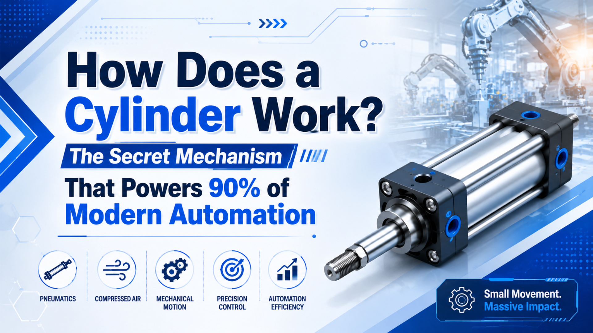
A pneumatic cylinder works by sending compressed air through a valve into one side of a sealed cylinder chamber. That air pressure pushes a piston. The piston moves a rod or carriage, and the opposite chamber exhausts through the valve. The machine sees the result as a push, pull, lift, clamp, stop, or transfer motion.
The simple force equation is F = P x A: pressure times effective piston area. At 100 psi, a 2-inch bore cylinder calculates to about 314 lbf before friction and pressure loss. But the full answer is not only the cylinder. The air path matters.
Key Takeaways
- A pneumatic cylinder works when compressed air fills one chamber and the opposite chamber exhausts.
- At 100 psi, a 2-inch bore calculates to about 314 lbf before losses.
- CAGI recommends no more than 10% pressure drop from compressor discharge to point of use.
- Most weak-cylinder problems start in pressure, flow, contamination, mounting, or exhaust.
What Happens Inside a Pneumatic Cylinder?
Inside a pneumatic cylinder, pressure acts on piston area and creates force. At 100 psi, a 2-inch bore calculates to about 314 lbf before losses, because NASA describes pressure force as p x A; that is the working core inside the actuator (NASA Glenn, 2026).
The piston is the moving pressure boundary. When compressed air enters the cap end, the piston moves toward the rod end. When air enters the rod end, the piston retracts. A double-acting cylinder uses air for both directions. A single-acting cylinder uses air for one direction and a spring, gravity, or external load for return.
The basic working path looks like this:
| Step | What Happens | What Can Go Wrong |
|---|---|---|
| Air supply | Compressor and receiver provide stored air. | Low supply pressure or unstable demand. |
| Air treatment | FRL prepares pressure, filtration, and lubrication where needed. | Water, clogged filters, or regulator droop. |
| Directional valve | Valve sends air to one chamber and vents the other. | Wrong porting, small flow path, sticky spool. |
| Cylinder chamber | Pressure pushes the piston and rod or carriage. | Seal leakage, side load, or back pressure. |
| Exhaust path | Opposite chamber vents through valve and muffler. | Blocked muffler or over-restricted speed control. |
The common mistake is watching only the regulator gauge. A cylinder does not work from the pressure printed on the regulator knob. It works from the pressure that reaches the active chamber while the load is moving. Measure there when the fault is intermittent.
For the underlying force theory, use the companion article on pneumatic cylinder theory. This article stays closer to the physical air path and the sequence of one working stroke.
How Does the Air Path Make the Piston Move?
The air path makes the piston move by filling one chamber faster than the opposite chamber can resist it. CAGI says a well-designed system should have no more than 10% pressure drop between compressor discharge and point of use, so the pipe, FRL, valve, tube, and muffler are part of the actuator (CAGI, 2026).
Start at the compressor, but do not stop there. Air normally travels through a receiver, dryer, main line, branch line, filter, regulator, directional valve, tube, fitting, and cylinder port. Each restriction can reduce the pressure or flow available at the piston.
During extension, the valve connects supply air to the cap end and connects the rod end to exhaust. During retraction, the valve reverses those paths. If either fill or exhaust is restricted, the cylinder may move slowly, stall, or slam.
This is why a FRL unit is not only an accessory. It protects the valve and cylinder, but it can also become a restriction if the bowl, element, regulator, or port size is wrong for the flow demand.
Directional Valve Job in the Cylinder Cycle
The directional valve decides which cylinder chamber receives supply air and which chamber exhausts. AutomationDirect’s cylinder overview separates single-acting and double-acting air cylinders, and a double-acting cylinder usually needs a valve that can switch supply and exhaust between two ports (AutomationDirect, 2026).
A single-acting cylinder often uses a 3/2 valve: pressure to extend, exhaust to return by spring or external force. A double-acting cylinder usually uses a 5/2 or 5/3 valve: one port feeds the cap end, one port feeds the rod end, and exhaust ports vent the inactive chamber.
The valve does three jobs at once:
- Selects direction.
- Supplies air.
- Releases trapped air from the opposite chamber.
If the valve is too small, the cylinder may never reach the expected speed. If the exhaust path is too restrictive, back pressure subtracts from the force you thought the piston had. If the valve center condition is wrong, the cylinder may drift, stop unexpectedly, or hold pressure when the machine should vent.
For electrical control, a solenoid valve turns the PLC signal into air routing. The electrical side can be correct while the pneumatic side is undersized. Check voltage, valve function, port size, flow rating, tube length, and muffler condition together.
How Do Force, Speed, and Stroke Work Together?
Force comes from pressure times area, but speed comes from flow filling and exhausting cylinder volume. At 100 psi, a 4-inch bore calculates to about 1,257 lbf before losses, while a 2-inch bore calculates to about 314 lbf, because force rises with piston area (NASA Glenn, 2026).
Stroke changes the air volume, not the static force. A long stroke takes more air to fill. If the valve and tubing do not provide enough flow, a larger cylinder can become slower even though it has more force.
The rod side changes retract force. A single-rod cylinder retracts with piston area minus rod area. That is why a cylinder can push strongly but pull weakly at the same pressure.
For pressure selection, use the companion article on air cylinder working pressure. This page explains the working sequence. The pressure article explains setpoint choice and energy tradeoffs.
Why Do Cylinders Stop Working Correctly?
Cylinders stop working correctly when the air path or mechanical path stops matching the load. DOE gives a point-of-use filter example with a 20 psi pressure drop, so a machine can have good header pressure and poor cylinder pressure at the same time (DOE Sourcebook, 2022).
Most troubleshooting should start before the cylinder is replaced. Check whether the fault appears in extension, retraction, both directions, or only during peak demand. Then measure pressure at the cylinder port while the machine runs.
Common causes include:
| Symptom | Likely Area | First Test |
|---|---|---|
| Weak push or pull | Pressure drop, bore sizing, load increase | Measure port pressure during stroke. |
| Slow motion | Valve flow, tubing, muffler, flow control | Compare speed with exhaust restriction removed safely. |
| Erratic motion | Water, dirt, seal drag, side load | Inspect air treatment and guide alignment. |
| Drift or movement at rest | Valve leakage, piston seal leakage, load path | Isolate chambers and check leakage direction. |
| Hard impact at end stroke | Cushion, speed setting, moving mass | Check cushion adjustment under real load. |
In our experience, random cylinder replacement is usually the slow path. If three cylinders fail at the same station, look at air quality, alignment, valve timing, and the load fixture. A new actuator will inherit the same bad circuit.
For a safety-specific failure mode, read how cylinder rod locks work. A rod lock is not a normal motion component. It is a mechanical holding device used when loss of air pressure can create a hazard.
What Role Do Seals, Guides, and Air Quality Play?
Seals, guides, and air quality keep the cylinder close to its intended behavior. ISO 8573-1 classifies compressed-air purity by particles, water, and oil, so an air-quality target should be specified instead of guessed when contamination is a repeated failure mode (ISO 8573-1, 2010).
Seals separate pressure chambers. A piston seal leaking across the piston reduces force and makes motion lazy. A rod seal leaking outward wastes air and may pull dirt into the rod area. A wiper helps keep external contamination away from the rod seal.
Guidance controls the load path. A standard cylinder is not a linear guide. If the machine applies side load, twisting load, or a long unsupported moment, use an external guide, guided cylinder, slide table, or rodless cylinder with the right carriage support.
Air quality does not need to be the same for every job. A dusty clamp station, food packaging machine, paint line, and electronics fixture can need different filtration, drying, and lubrication choices.
Check these items before blaming the cylinder:
- Water in filter bowls.
- Filter element condition.
- Regulator droop during motion.
- Oil or dirt at valve exhaust.
- Rod scoring.
- Side load from a bracket or misaligned guide.
- Cushion setting after the machine reaches normal speed.
A flow-control valve can tune speed, but it cannot repair dirty air, side load, or a leaking piston seal.
How Do Sensors and PLC Control Fit Into the Cycle?
Sensors and PLC control tell the machine when the cylinder reached the required state. AutomationDirect’s video shows the cylinder mechanism, but in a production machine the PLC usually also needs position confirmation from reed switches, electronic sensors, pressure switches, or external encoders (AutomationDirect video, 2026).
A simple station may only need two end-position sensors: extended and retracted. The PLC energizes the solenoid valve, waits for the correct sensor, and then allows the next machine step. If the signal does not arrive in time, the program raises a fault.
More complex stations may monitor pressure, time, and cycle count. That data helps separate a real cylinder fault from a supply-air problem. For example, a slow extension with low port pressure is different from a slow extension with normal pressure and a binding guide.
Modern controls are useful, but they do not change the air path. The PLC cannot overcome an undersized valve or a clogged muffler. It can only show you that the motion did not happen as expected.
For machine-control context, connect cylinder pages to control components and the relevant valve family. Buyers often need the actuator and valve reviewed together, not as isolated catalog choices.
Single-Acting, Double-Acting, and Rodless Cylinder Differences
Single-acting, double-acting, and rodless cylinders use pressure-area logic, but their output geometry differs. SMC’s MB1 catalog lists 0.05 MPa minimum operating pressure, and AutomationDirect separates single-acting and double-acting air cylinder types (SMC MB1, 2025; AutomationDirect, 2026).
Single-acting cylinders are simple and use less air because only one direction is powered. They fit short strokes, light loads, and fail-return behavior where a spring or gravity can bring the actuator back.
Double-acting cylinders are better when both directions need powered motion. They are common for clamps, pushers, lifters, stops, and transfer stations because the valve controls both extension and retraction.
Rodless cylinders put the moving load on a carriage instead of an extending rod. Use them when the stroke is long and the machine does not have space for a rod to extend beyond the body.
| Type | How It Works | Best Fit |
|---|---|---|
| Single-acting | Air powers one direction, spring or gravity returns. | Simple short-stroke push or release motion. |
| Double-acting | Air powers extension and retraction. | General automation with controlled motion both ways. |
| Rodless | Internal piston moves an external carriage. | Long travel in a compact machine envelope. |
The right type depends on load, stroke, available space, safety state, guidance, and speed. A short clamp may be simple. A long transfer axis needs a different review.
What Should You Include in a Cylinder RFQ?
A good RFQ should describe the motion, not only the old part number. SMC’s MB1 example lists piston speed from 50 to 1000 mm/s for many sizes, which shows why stroke time, load, and air path belong in the inquiry, not only bore and stroke (SMC MB1, 2025).
A useful note sounds like this: “Double-acting cylinder, 50 mm bore, 300 mm stroke, horizontal load 80 kg, target stroke time 0.6 s, 6.5 bar regulator, port pressure drops to 5.1 bar during extension, valve 5/2, tube 8 mm.” That tells an engineer where to check force, flow, and pressure.
Send these details:
- Cylinder type and old model code.
- Bore, stroke, rod diameter, and mounting.
- Load mass, direction, and side-load condition.
- Target stroke time and cycle rate.
- Working pressure at the regulator and measured port pressure if available.
- Valve type, valve port size, tube size, and fitting route.
- Air quality, water, oil, dust, temperature, or washdown exposure.
- Sensor type, voltage, wiring, and required default state.
- Photos of the installed cylinder and surrounding guide or bracket.
- Failure symptom: weak, slow, leaking, drifting, slamming, or sticking.
For direct help, send the details through engineering RFQ support. The best replacement is not always a larger cylinder. Sometimes the right answer is a valve change, shorter tubing, a guided actuator, a better mount, or cleaner air.
Conclusion
A pneumatic cylinder works when compressed air reaches the active chamber, pressure acts on piston area, the opposite chamber exhausts, and the load path lets the piston move. CAGI’s 10% pressure-drop guidance is a practical reminder that the whole air path affects the motion, not just the cylinder body (CAGI, 2026).
Start with the sequence. Supply air enters the FRL. The valve routes air to one cylinder chamber. Pressure pushes the piston. Exhaust leaves the other chamber. Sensors confirm the position. If motion fails, test that sequence before replacing parts.
That is the practical secret. The cylinder is not a magic force box. It is the visible end of a compressed-air circuit.
FAQs About How Pneumatic Cylinders Work
These FAQs summarize the working sequence in field terms. NASA gives the pressure-force relationship as p x A, while CAGI gives a 10% pressure-drop target from compressor discharge to point of use, so both force and air delivery must be checked (NASA Glenn, 2026; CAGI, 2026).
How does a pneumatic cylinder work?
A pneumatic cylinder works by sending compressed air into one chamber so pressure pushes a piston. The piston moves a rod or carriage, while the opposite chamber exhausts through a valve. The resulting linear motion can push, pull, lift, clamp, stop, or transfer a load in automation equipment.
What makes a pneumatic cylinder extend and retract?
A directional valve makes the cylinder extend and retract. For extension, the valve sends air to the cap end and vents the rod end. For retraction, it reverses the air path. A single-acting cylinder may use a spring or gravity for the return direction instead of powered retraction.
Why is my pneumatic cylinder weak even with normal pressure?
The regulator may show normal pressure while the cylinder port drops during motion. Common causes include clogged filters, undersized valves, long narrow tubing, restricted mufflers, leaking seals, side load, or a heavier-than-expected load. Measure pressure at the cylinder port during the stroke.
Does cylinder speed depend on pressure or flow?
Both matter, but they do different jobs. Pressure creates force. Flow fills and exhausts the chamber volume over time, which controls speed. A cylinder can have enough pressure and still move slowly if the valve, tubing, flow control, or exhaust muffler restricts flow.
What is the difference between single-acting and double-acting cylinders?
A single-acting cylinder uses air pressure for one direction and a spring, gravity, or external force for return. A double-acting cylinder uses air pressure for both extension and retraction. Double-acting designs give better control in both directions and are common in machine automation.
What information is needed to replace a pneumatic cylinder?
Send the cylinder type, bore, stroke, rod diameter, mounting style, port size, sensor details, working pressure, load, target speed, environment, old model code, and clear photos. If the machine has a fault, include whether it is weak, slow, leaking, drifting, slamming, or sticking.
Sources
- NASA Glenn: Aerodynamic Force, pressure times area relationship for force. Retrieved 2026-06-03.
- NASA Glenn: Pascal’s Principle, pressure transmission in confined fluids. Retrieved 2026-06-03.
- CAGI: Working With Compressed Air, compressed-air pressure-drop guidance. Retrieved 2026-06-03.
- U.S. Department of Energy: Improving Compressed Air System Performance, Third Edition, point-of-use pressure-drop example and compressed-air system guidance. Retrieved 2026-06-03.
- ISO 8573-1:2010, compressed-air purity classes for particles, water, and oil. Retrieved 2026-06-03.
- SMC: Series MB1 Air Cylinder catalog, operating pressure and piston-speed example for standard industrial air cylinders. Retrieved 2026-06-03.
- AutomationDirect: Pneumatic Air Cylinders, single-acting and double-acting pneumatic cylinder overview. Retrieved 2026-06-03.
- AutomationDirect: What is a Pneumatic Cylinder?, YouTube-backed pneumatic cylinder explainer video. Retrieved 2026-06-03.