

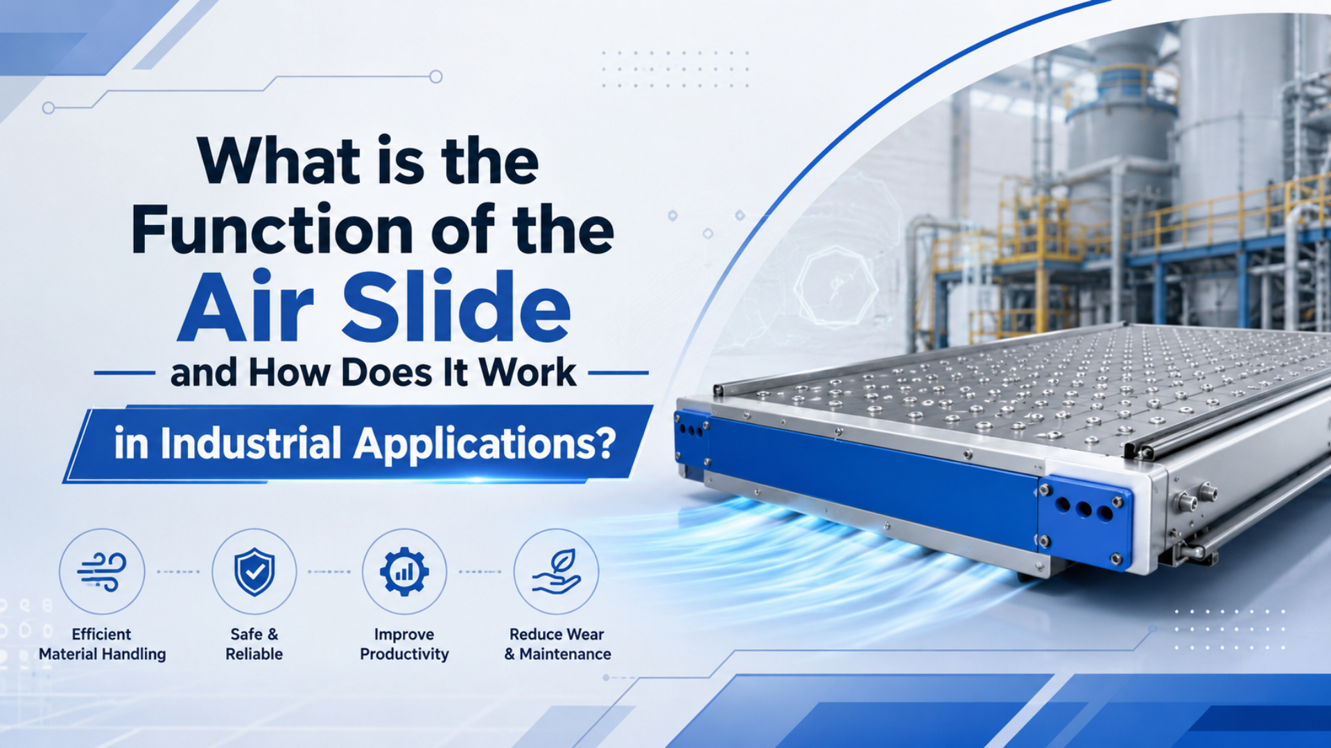
An air slide is a pneumatic linear-motion assembly that moves a carriage, table, or load with compressed air while a guide structure carries side load and moment. In industrial automation, the function is simple: move parts smoothly between fixed positions without the long exposed rod of a conventional cylinder.
Air supplies force. Guidance supplies discipline.
The term “air slide” is used loosely, so define it before selecting parts. It may mean a compact pneumatic slide table, a guided cylinder, or a rodless pneumatic cylinder with an external carriage. Parker’s OSP-P rodless cylinder catalog lists bore sizes from 10-80 mm, 8 bar maximum operating pressure, and long-stroke versions up to 41 m (Parker OSP-P catalog, 2025). That is a much better starting point than the vague phrase “long stroke air slide.”
Key Takeaways
- Air slides use compressed air for linear motion, but the guide, carriage, and load moments decide whether the system survives.
- Parker lists standard OSP-P strokes up to 6000 mm and long-stroke versions up to 41 m for rodless pneumatic applications.
- SMC MY1B guided rodless cylinders list 0.1-0.8 MPa operating pressure and 100-1000 mm/s piston speed, useful boundaries for early sizing.
How Do Air Slides Create Linear Motion?
Air slides create linear motion by turning compressed-air pressure into force while a slide, rail, or carriage controls the load path. SMC’s MY1B mechanically jointed rodless cylinder lists 0.1-0.8 MPa operating pressure and 100-1000 mm/s piston speed (SMC MY1B catalog, 2025). Those numbers show why pressure, speed, and guide load must be checked together.
In a basic double-acting pneumatic slide, air enters one side of the actuator and exhausts from the other side. The pressure difference moves the piston or drive element. The carriage then carries the workpiece, fixture, stopper, pusher, or tooling. That sounds straightforward. The trouble starts when the carriage receives side load it was not designed to carry.
Rodless air slides solve the space problem that appears when a long rod cylinder extends. Instead of a rod projecting out of the barrel, the piston connects to an external carriage through a mechanical band or magnetic coupling. The load travels beside the cylinder body, which keeps the installation compact.
The most useful definition is this: an air slide is not just an actuator. It is a small linear-motion system. Treat it as a system and you will check load mass, moment arm, stroke, speed, cushioning, mounting stiffness, air quality, and sensing before you approve the part number.
The force math still starts with the familiar equation:
Force = Pressure x Effective piston areaThat equation does not include friction, seal drag, guide resistance, fixture inertia, or end-of-stroke impact. It also does not check whether the guide can handle pitch, roll, and yaw moments. Good selection work adds those items before the quote goes out.
What Are the Main Types of Air Slides Available?
The main air-slide families are pneumatic slide tables, guided cylinders, and rodless cylinders with external carriages. Parker’s OSP-P catalog lists a basic rodless cylinder plus linear guide variants, while SMC’s MY1B catalog shows guided rodless constructions with selectable slide-bearing, cam-follower, and linear-guide configurations (Parker OSP-P catalog, 2025).
Use a compact pneumatic slide table when the stroke is short and the load needs a stable table surface. These are common in pick-and-place stations, inspection fixtures, light presses, small ejectors, and indexing stops. They are tidy. They are not magic, so check allowable moment before adding a tall bracket.
Use a guided cylinder when the cylinder needs extra rod support or when the tooling creates a side load. Twin-rod and guide-rod cylinders are easier to understand than many rodless systems, but they still take up rod-extension space. They are useful when the stroke is moderate and the motion is mostly between two positions.
Use a rodless pneumatic cylinder when stroke length or machine footprint is the real constraint. Parker’s catalog lists free choice of stroke length up to 6000 mm in 1 mm steps for standard OSP-P units, with longer strokes on request and long-stroke versions up to 41 m (Parker OSP-P catalog, 2025). That is where rodless designs earn their keep.
The naming matters during procurement. If a buyer asks for an “air slide” and sends only a photo, one supplier may quote a compact slide table while another quotes a rodless cylinder with a separate guide. Both could look reasonable. Only one may fit the machine. Put the functional requirement in the RFQ before the part-family name.
| Air slide type | Best fit | Selection risk | What to verify |
|---|---|---|---|
| Pneumatic slide table | Short-stroke tooling and small fixtures | Moment overload from tall tooling | Table moment, stroke, repeatability, shock absorber |
| Guided cylinder | Moderate stroke with side-load control | Rod space and guide binding | Rod load, guide load, alignment, mounting stiffness |
| Rodless cylinder | Long stroke and compact machine footprint | Carriage moment and belt or seal wear | Load mass, moment, speed, support spacing, cushioning |
| Air-bearing slide | Precision, low-friction motion | Air quality and stiffness limits | Flatness, supply cleanliness, payload, control method |
Where Are Air Slides Most Commonly Used?
Air slides are most useful where a machine needs repeatable linear transfer, indexing, pushing, lifting, or positioning without high servo precision. ISO 14644-1 classifies cleanrooms by airborne particle concentration (ISO 14644-1, 2015), which is why cleanroom pneumatic slides need different material, lubrication, and exhaust choices than ordinary packaging equipment.
In assembly equipment, air slides move nests, clamps, inspection cameras, label heads, reject pushers, escapements, and part-transfer tooling. The motion is usually two-position or multi-position with external stops. What matters most? Repeatable hard stops, stable guidance, and controlled impact.
In packaging lines, air slides push cartons, index trays, divert packages, and transfer products between conveyors. For food packaging, material selection must account for food-contact rules when components can contact product or packaging surfaces. FDA’s food-contact-substance resources are the right regulatory starting point for U.S.-bound projects (FDA, 2026).
In electronics and pharmaceutical work, the slide may be selected less for raw force and more for cleanliness, speed control, and gentle handling. Low particle generation, compatible seals, clean exhaust routing, and suitable lubrication become part of the actuator decision. A standard shop-floor slide may not belong in that environment.
Environment changes the answer fast.
From what we’ve seen, replacement requests often fail because the buyer sends only stroke and bore. A better RFQ includes stroke, moving mass, mounting orientation, speed target, stop method, sensor type, guide-load direction, and whether the slide works near food, washdown, or cleanroom conditions.
How Do Air Slides Compare to Other Pneumatic Actuators?
Air slides beat ordinary rod cylinders when long stroke or guided load support matters, but they do not automatically beat electric actuators for positioning accuracy. Enfield’s rodless-cylinder positioning demo uses a Parker Origa guided rodless cylinder and external feedback to show velocity and position control (Enfield Technologies, 2026). That extra control hardware is the clue.
A basic air slide is excellent for moving between stops. It can be fast, compact, and durable when the load is well guided. It is not a servo axis unless the valve, feedback, controller, and mechanical slide are selected as a motion-control package.
Compared with a standard rod cylinder, an air slide handles external loads better because the slide or guide carries side forces. Compared with a rodless cylinder without a guide, a guided air slide is usually safer for direct-mounted loads. Compared with an electric actuator, an air slide is usually simpler, but it gives up programmable motion and high-resolution positioning unless extra controls are added.
The practical comparison is this:
- Use a rod cylinder for simple push-pull motion with little side load.
- Use a guided cylinder when side load exists but the stroke is moderate.
- Use a rodless air slide when stroke length or footprint matters most.
- Use an electric actuator when position profiles, acceleration control, or many intermediate stops matter.
What Are the Key Benefits of Using Air Slides?
The main benefit of an air slide is compact guided linear motion, especially over strokes that would make rod cylinders awkward. Parker’s OSP-P line lists standard stroke choice up to 6000 mm and long-stroke cylinders up to 41 m on request (Parker OSP-P catalog, 2025). That makes the footprint advantage concrete.
The second benefit is simpler machine integration. Compressed air is already available in many packaging, assembly, and material-handling plants. A slide can often be controlled with a directional valve, flow controls, sensors, and hard stops. Keep it simple when the process only needs two positions.
The third benefit is separation of drive and guidance. Instead of asking the piston rod to tolerate side load, the guide system carries the load path. That reduces bending risk and makes the motion easier to repeat. Still, the guide rating is not infinite. Moment checks matter.
For replacement RFQs, the most helpful one-line note is specific: “Stroke 1200 mm, horizontal mount, moving load 18 kg, carriage overhang 90 mm, target extend time 1.2 s, two end sensors, clean dry air, no washdown.” That tells an engineer how to check the slide instead of guessing from a photo.
How Should Engineers Size and Maintain an Air Slide?
Size an air slide by calculating force, checking guide load, and verifying speed and cushioning. Parker’s OSP-P catalog warns that permissible loads, forces, moments, mass to be cushioned, and piston speed at the start of cushioning decide the cylinder choice (Parker OSP-P catalog, 2025). That is the sizing checklist in one sentence.
Start with the load. Record moving mass, tooling overhang, mounting orientation, and whether the slide pushes, pulls, lifts, or transfers. Then check the moment. A light part on a long bracket can overload a guide faster than a heavier part mounted close to the carriage.
Next, check speed. SMC’s MY1B table lists 100-1000 mm/s piston speed for the referenced guided rodless cylinder specification (SMC MY1B catalog, 2025). That does not mean every load can run at the top of the range. Cushioning and impact energy decide what is realistic.
Maintenance is mostly about air quality, alignment, seals, guides, and stops. Watch for drift, bounce at the stop, uneven speed, air leakage, rail contamination, and repeated flow-control adjustments. If operators keep turning the flow controls, the slide is giving you a symptom.
One symptom is enough to measure.
Use this field checklist:
- Confirm pressure at the slide while it is moving.
- Check the load centerline against guide ratings.
- Inspect rails, wipers, and mounting bolts.
- Verify end cushions or shock absorbers are not bottoming.
- Confirm sensors switch at the expected positions.
- Review air filtration, moisture, and lubrication requirements.
- Record cycle time before and after adjustment.
Conclusion
An air slide functions as a guided pneumatic linear-motion system, not merely a cylinder with a table attached. Parker publishes rodless pneumatic cylinders with 8 bar maximum operating pressure, standard strokes up to 6000 mm, and long-stroke versions up to 41 m (Parker OSP-P catalog, 2025). That range explains why air slides appear in both compact fixtures and long transfer systems.
The right selection habit is simple. Define the slide type. Calculate force. Check moment. Confirm speed. Verify cushioning. Match the environment. Then write the RFQ with enough information for a supplier to check the load path, not just the bore and stroke.
FAQs About Air Slides
Air-slide questions usually come down to function, load, stroke, control, and environment. Parker’s OSP-P catalog lists 10-80 mm bores and up to 41 m long-stroke versions, while SMC lists 0.1-0.8 MPa operating pressure for one MY1B guided rodless specification (Parker OSP-P catalog, 2025). Those catalog limits are better than generic rules.
What is an air slide used for?
An air slide is used to move a load in a straight line with compressed air while a guide or carriage controls side load. Common uses include part transfer, indexing, reject pushing, fixture movement, carton handling, inspection station movement, and compact long-stroke motion where a standard rod cylinder would take too much space.
How does an air slide work?
Most air slides use a double-acting pneumatic actuator. Air pressure moves an internal piston or drive element, and the external carriage moves the load along a guided path. In rodless designs, the carriage follows the piston without an exposed rod, which keeps the installation shorter for long strokes.
What is the difference between an air slide and a rodless cylinder?
A rodless cylinder is one common type of air slide, but not every air slide is rodless. The broader term can include compact slide tables and guided cylinders. A rodless cylinder is best when stroke length and footprint matter. A slide table is usually better for short, compact, guided tooling motion.
What pressure does an air slide need?
Pressure depends on the slide design and load. One SMC MY1B guided rodless specification lists 0.1-0.8 MPa operating pressure, while Parker lists 8 bar maximum operating pressure for the OSP-P rodless cylinder. Always check the specific catalog and verify pressure at the slide during motion.
Can an air slide stop at intermediate positions?
Yes, but intermediate stopping usually needs more than a basic on-off valve. Use external stops, shock absorbers, brakes, proportional valves, position sensors, or a closed-loop positioning system depending on accuracy needs. The Enfield rodless-cylinder demo shows velocity and position control with feedback, not a bare cylinder alone.
How do you choose the right air slide?
Choose by stroke, moving mass, load moment, speed, cushioning, mounting orientation, sensing, and environment. Do not select only by bore and stroke. For replacement work, send photos plus load mass, overhang, cycle time, pressure, port size, sensor style, and any cleanroom, food, washdown, or dust exposure.
Sources
- Parker: OSP-P Pneumatic Rodless Cylinders and Linear Guides, rodless cylinder sizes, 8 bar maximum pressure, stroke options, load/moment guidance, and long-stroke versions up to 41 m. Retrieved 2026-06-03.
- SMC: MY1B Mechanically Jointed Rodless Cylinder catalog, operating pressure, proof pressure, piston speed, and guided rodless cylinder selection data. Retrieved 2026-06-03.
- Enfield Technologies: S2 Positioning - Better Rodless Cylinder Positioning, video demo of a guided Parker Origa rodless cylinder with velocity and position control. Retrieved 2026-06-03.
- ISO 14644-1:2015, cleanroom air cleanliness classification by particle concentration. Retrieved 2026-06-03.
- FDA: Packaging & Food Contact Substances, food-contact material regulatory resources for food and packaging applications. Retrieved 2026-06-03.