

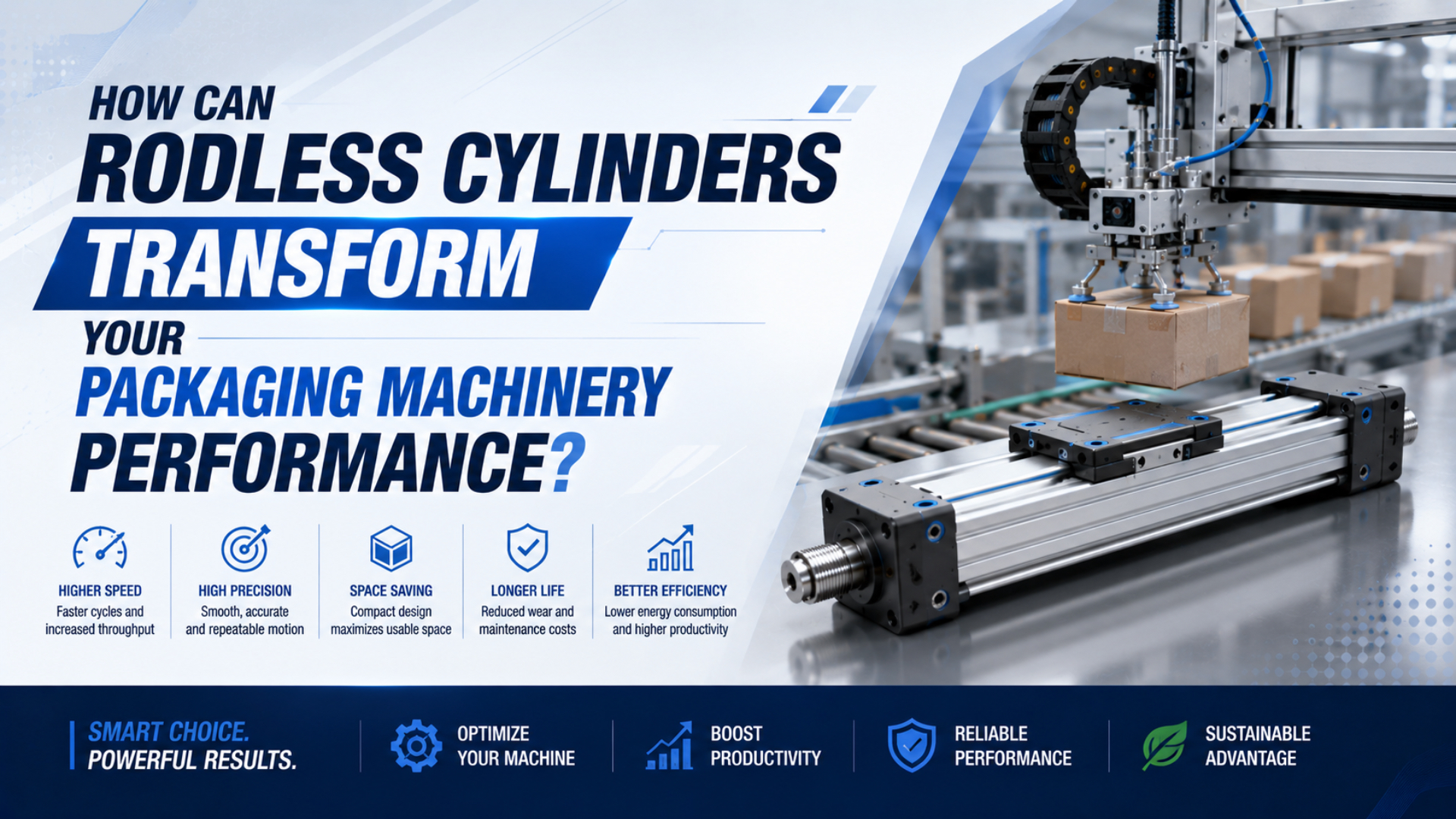
Rodless cylinders can improve packaging machinery when they remove an envelope constraint, simplify a linear transfer, or place the load on a better guide. They don’t create a universal throughput gain. The result depends on stroke time, moving mass, load offset, cushioning, controls, air supply, contamination exposure, and the acceptance test used on the actual station.
A productive retrofit starts by naming the bottleneck. Is the machine too long, is a transfer point causing jams, or is the axis missing its timing window? Once that is clear, the cylinder becomes one part of a testable motion system rather than a shortcut to a promised percentage.
A packaging rodless-cylinder retrofit is the redesign of a station’s linear motion around a cylinder whose piston moves an external carriage without an extending rod. Festo says the actuator can be half as long as a conventional cylinder at the same stroke, but it also identifies slot contamination as a limitation. Parker catalogs strokes to 6000 mm, while SMC requires load mass, static moment, and dynamic moment to be checked for its guided MY1H series. Those facts set useful boundaries, not a performance guarantee. Approve the change only after the installed station meets its travel-time, settling, pressure, stopping, fault-response, cleaning, and service-access requirements with the real payload. Test nominal production, the lowest allowed supply pressure, the heaviest approved package, and recovery after an induced fault (Festo, 2026; Parker, 2025; SMC, 2025).
Key Takeaways
- Festo says a rodless cylinder is half as long at the same stroke, but its slot raises contamination concerns in dusty or washdown packaging areas.
- Check load and stopping duty.
- Separate process sensors from safety-rated protective functions.
- Approve with synchronized cycle, pressure, repeatability, fault-response, cleaning, and access evidence.
Where Do Rodless Cylinders Create Real Packaging-Line Value?
Use a rodless cylinder when packaging motion needs long travel inside a short envelope, not because the line merely needs more speed. Festo states that piston-rodless cylinders are half as long as conventional cylinders at the same stroke, while also noting greater sensitivity to dirt at the slot (Festo, 2026).
The strongest applications are usually point-to-point transfers with clear end positions. Examples include moving a carton between lanes, repositioning a guide rail during format change, carrying a pusher across a wide conveyor, or indexing a lightweight tooling plate. A guided version can also support pick-and-place motion when the required positions, loads, and stop behavior fit pneumatic control. Not every compact axis is a good candidate. Continuous contouring, many recipe positions, tight velocity regulation, or coordinated interpolation may favor an electric linear actuator. A heavily offset payload can also make the guide package, not the cylinder bore, the deciding component.
| Packaging task | Rodless fit | Main evidence to request |
|---|---|---|
| Lane change or carton transfer | Strong when two positions and long travel dominate | Stroke time, end-position repeatability, jam recovery |
| Pusher or diverter | Conditional on impact and side-load control | Product force, stopper load, cushion margin |
| Format adjustment | Strong for two or a few verified positions | Locking method, recipe confirmation, changeover test |
| Pick-and-place axis | Conditional on guide and control architecture | Payload center, orientation, settling time |
| Continuous following or contouring | Usually weak for a standard pneumatic axis | Compare servo-pneumatic and electric options |
For a broader architecture comparison, see the complete rodless cylinder benefits analysis. The important step here is narrower: match the actuator to one packaging-station constraint and define how that constraint will be measured.
Packaging Footprint Is an Envelope Problem
Start with the installed envelope. Parker offers OSP-P strokes up to 6000 mm in 1 mm increments, but its catalog also calls for mid-section supports when unsupported length and load would create excessive deflection or vibration (Parker OSP-P catalog, 2025).
Removing the rod helps. The surrounding hardware still occupies space: end caps, ports, fittings, flow controls, switches, cable routing, shock absorbers, guards, adjustment access, and the clearances needed to use them. Long axes may also need mid-supports and a frame surface that holds their alignment. Service access belongs in the same drawing. A compact axis that requires removing a conveyor or guard to reach a cushion screw can lengthen a small maintenance task. Show the carriage at both ends, then overlay the tool clearance needed to replace a sensor, disconnect a tube, or inspect the sealing bands.
The useful footprint is the swept motion plus the service envelope, not the actuator’s catalog length. This distinction explains why two mechanically valid layouts can produce very different changeover and maintenance experiences even when both use the same stroke.
For unusually long transfers, compare this station-level review with the long-stroke conveyor sizing guide. It covers support spacing, flow, and guide decisions in more depth.
Can the Axis Meet Cycle Time Without End-of-Stroke Impact?
Treat cycle time as a test result, not a cylinder catalog promise. SMC’s MY1H selection procedure evaluates dynamic moment using collision speed equal to 1.4 times average speed; the same catalog requires load mass, static moment, and dynamic moment to be checked (SMC MY1H catalog, 2025).
Break the station cycle into command delay, valve response, chamber filling, travel, controlled deceleration, settling, sensor confirmation, and dwell. The cylinder affects several of those intervals, but the slowest interval may be a product sensor, a downstream permissive, or a restricted exhaust path. Timing only the full machine cycle hides that cause. Timing has to be decomposed. Measure pressure at both cylinder ports during motion. A static regulator reading cannot show whether supply pressure collapses during acceleration or exhaust backpressure slows the return. Log the controller command, both pressure traces, end-position signals, and station-ready signal on the same time base.
In our experience, the overlooked variable in application reviews is often the load center rather than the nominal payload. A light gripper on a long bracket can create more dynamic moment and longer settling than a heavier load mounted close to the carriage.
SMC also states that its MY1B air cushion is intended to prevent excessive end impact, not to decelerate the piston throughout the approach. When load and speed exceed the catalog cushion limit, use an appropriate shock absorber or change the motion design (SMC MY1B catalog, 2025).
The high-speed packaging sorting guide provides a detailed timing-budget and factory-acceptance workflow. Use it when a few milliseconds matter; don’t substitute a no-load bench speed for the installed result.
Which Load and Guide Checks Prevent Early Failure?
Size the guide and cushion together. The MY1H catalog requires the combined guide load factor to remain at or below 1 for the selected configuration, while Parker limits deflection between specified mid-section supports to 0.5 mm (SMC MY1H, 2025; Parker OSP-P, 2025).
Count every moving part. Include product, tooling, carriage-mounted plate, tubing loop, cable carrier, and carried sensor hardware before locating the combined center of gravity in all three axes. That geometry creates pitch, yaw, and roll moments that a simple force calculation misses.
Check at least four operating states:
- Rest at either end.
- During full acceleration, include inertia and any dynamic loss of supply pressure.
- At cushion or stopper engagement, use the applicable collision speed and resulting dynamic moment.
- During jam clearing or manual recovery, account for maintenance forces that can differ from production and act through a larger lever arm.
Use the exact model’s speed-dependent graphs and combined-load method. Do not transfer an allowable moment from another bore, guide style, or manufacturer. If an external guide carries the load, protect the cylinder from parallelism error with the mounting freedom specified by the manufacturer. Parker warns that parallelism deviation can strain the piston and offers clevis mounting to provide compensation. The guide-rail parallelism tolerance guide explains that installation problem. For the RFQ, include load-center coordinates, speed at cushion entry, orientation, support locations, and the assumed stopping device.
Multi-Axis Coordination Is a Control Architecture
Separate sequential coordination from coordinated motion. ISO 13849-1:2023 covers safety-related control parts across electrical, hydraulic, pneumatic, and mechanical technologies in high-demand and continuous operating modes, but it does not select the required performance level for a particular application (ISO 13849-1:2023, 2023).
Two pneumatic axes can work well when each moves between verified end states and the controller advances only after the required permissives are true. That is checkpoint coordination. It suits many cartoning, pushing, clamping, and transfer sequences because the motion path between checkpoints does not need continuous interpolation. Coordinated trajectory control is different. If X and Y must maintain a defined path relative to each other, end switches are insufficient. The design needs continuous position feedback, valves and controllers capable of the required closed-loop behavior, and a commissioning method that checks tracking error across payload and pressure conditions.
Endpoint checks are not trajectory control.
Removing a mechanical transfer point can simplify a packaging sequence, but adding pneumatic axes does not automatically create flexible three-dimensional motion. The real dividing line is whether the process cares only about verified states or about the path between them.
When several intermediate positions matter, review the difference between pneumatic repeatability and accuracy. Electric motion is often the cleaner choice when recipes demand many positions or tightly controlled trajectories.
How Should Collision Prevention Be Engineered?
Build collision prevention from a documented risk assessment, not a magnetic switch list. ANSI/PMMI B155.1-2023 applies to new, modified, or rebuilt packaging machinery and covers conveying plus coordinated packaging functions. PMMI says the standard guides suppliers and users through a formal, documented risk-assessment process (PMMI, 2023).
A cylinder switch reports one piece of state. It does not by itself identify every jam, guarantee that another axis is clear, or make a normal PLC input safety-rated. Define the hazard first, then choose prevention, safeguarding, stopping, and restart measures appropriate to the risk.
A practical control chain separates these functions:
- Process detection: inputs report machine state.
- Motion permissives: the controller verifies that conflicting axes and tools are clear before issuing a command.
- Safety functions: guarding, interlocks, emergency stopping, monitored pneumatic energy control, fault tolerance, and diagnostic coverage are designed and validated against the required safety performance.
- Fault response: timeouts, contradictory signals, or pressure faults create a defined stop and block automatic restart.
- Recovery: the operator receives controlled fault-clearing instructions, clear status information, and a restart sequence that cannot bypass the protective function.
ISO 12100:2010 supplies the broader methodology for hazard identification, risk estimation, risk reduction, documentation, and verification across the machine life cycle (ISO 12100:2010, 2010). Apply that process to the complete packaging machine, not only to the actuator.
What Changes in Washdown, Food, or Dusty Packaging?
For food packaging, actuation suitability begins with cleanability and access. FDA modernized its food current good manufacturing practices into 21 CFR Part 117 in 2015, covering plant equipment and sanitary operations; FDA guidance points to 117.40(a)(1), which requires equipment and utensils to be adequately cleanable (FDA, 2026).
A standard slotted rodless cylinder should not be presumed washdown-ready. Festo notes that the cylinder slot makes this design more sensitive to dirt even with covering bands. In wet or dusty duty, verify the exact model’s ingress protection, corrosion resistance, approved cleaning chemicals, lubrication policy, drain orientation, and sealing-band inspection method. Appearance isn’t a qualification. Location matters. An actuator outside the product zone, driving through a protected linkage, faces different sanitation requirements from a carriage above exposed food or primary packaging. FDA guidance for ready-to-eat food equipment recommends minimizing microbial harborage sites and keeping relevant equipment surfaces accessible for cleaning (FDA equipment guidance, 2017).
Ask the machine builder to mark hygienic zones on the layout. Then document which actuator surfaces can be contacted by product, splash, foam, dust, or condensate. If a slotted design cannot be cleaned and inspected reliably in that zone, consider a protected installation, an inverted arrangement approved by the supplier, a magnetically coupled cylinder, or another actuator technology.
A Five-Gate Packaging Retrofit Decision
Gate the retrofit with five sets of evidence. Parker’s catalog allows OSP-P strokes up to 6000 mm, while SMC’s selection method uses three load categories: mass, static moment, and dynamic moment. Those figures prove a model range can be broad, not that any model will pass your station.
Gate 1: Motion intent. Define every commanded position, working stroke, overtravel allowance, orientation, dwell, cycle-time target, and permitted variation in the path or arrival time. State whether the axis is point-to-point, checkpoint-coordinated, or continuously controlled.
Gate 2: Mechanical load path. Submit moving mass, center-of-gravity coordinates, guide type, support spacing, mounting flatness, stopper location, and worst jam or recovery load. Require the supplier’s model-specific load-factor and cushion review.
Gate 3: Pneumatic delivery. Record minimum dynamic supply pressure, valve part number, tube inside diameter and length, metering direction, exhaust restrictions, and pressure traces at the actuator. The selected valve must support the required motion under simultaneous plant demand.
Gate 4: Environment and safety. Identify dust, washdown, temperature, cleaning chemicals, hygienic zone, guarding, interlocks, energy isolation, fault response, and restart behavior. Tie each safety function to the machine’s documented risk assessment.
Gate 5: Acceptance evidence. Test the real payload across the working pressure range. Record travel time, settling time, end-position result, pressure at both ports, cushion behavior, repeated cycles, jam recovery, changeover, and access for planned inspection.
Package the evidence for procurement. If the supplier cannot reproduce its selection against your payload geometry and operating speed, the RFQ is not yet complete. Use the high-speed cylinder specification checklist as a companion when the duty data needs a more detailed handoff.
Rodless Cylinder Packaging FAQs: What Should Buyers Ask?
Five boundaries answer the common questions. The screening references are Parker’s 6000 mm stroke envelope and SMC’s 140% collision-speed factor, alongside the 2023 PMMI packaging-machine safety standard and FDA Part 117. Final approval still belongs to the selected model’s catalog and the installed machine risk assessment.
Does a rodless cylinder always reduce packaging-machine length by half?
No. Festo says the actuator itself is half as long as a conventional cylinder at the same stroke, but the installed machine also needs end caps, fittings, stops, sensors, supports, guards, and service access. Compare complete swept and maintenance envelopes before claiming a machine-level reduction.
What speed should I specify for a packaging rodless cylinder?
Start with the duty. Specify stroke time, moving mass, load center, orientation, and the speed entering a cushion or stopper. SMC uses collision speed equal to 1.4 times average speed in its MY1H dynamic-moment method. Approve the result from the exact model’s speed-dependent load and cushion data.
Can a standard pneumatic rodless cylinder stop at many package positions?
Not by itself. Standard switches normally verify selected positions rather than control a continuous path. Several repeatable positions require suitable feedback, valve behavior, controller logic, and a verified stopping method. When recipes demand many tightly controlled positions, compare servo-pneumatic and electric linear motion before selecting hardware.
Is a slotted rodless cylinder suitable for food washdown?
Only after a zone review. Festo notes that the slot increases dirt sensitivity, while FDA Part 117 requires adequately cleanable equipment used in food production. Verify materials, ingress protection, cleaning chemicals, drainage, lubrication, band inspection, and access instead of treating a stainless-looking assembly as washdown-ready.
What information belongs in a packaging rodless-cylinder RFQ?
Include stroke, orientation, cycle timing, moving mass, load-center coordinates, guide arrangement, dynamic supply pressure, valve and tubing details, stopping method, environment, sensors, safety states, support locations, and acceptance tests. Parker and SMC selection data are model-specific, so part number approval should follow a documented load and cushion review.
Sources and technical references
- Festo, Rodless cylinders, length and contamination limits. Retrieved 2026-07-27.
- Parker, OSP-P Pneumatic Rodless Cylinders and Linear Guides, stroke, support, mounting, and deflection guidance. Retrieved 2026-07-27.
- SMC, Series MY1H Mechanically Jointed Rodless Cylinder, load-factor and dynamic-moment selection. Retrieved 2026-07-27.
- SMC, MY1B catalog, cushion limits. Retrieved 2026-07-27.
- PMMI, ANSI/PMMI B155.1-2023 release, formal risk-assessment guidance for suppliers and users of new, modified, or rebuilt packaging and processing machinery. Retrieved 2026-07-27.
- ISO 12100:2010, machinery risk assessment and risk reduction. Retrieved 2026-07-27.
- ISO 13849-1:2023, safety-related control-system design and integration. Retrieved 2026-07-27.
- FDA, Current Good Manufacturing Practices, 21 CFR Part 117 overview. Retrieved 2026-07-27.
- FDA, Control of Listeria monocytogenes in Ready-To-Eat Foods, equipment cleanability, microbial-harborage reduction, accessible food-contact surfaces, and review of installed equipment modifications. Retrieved 2026-07-27.