

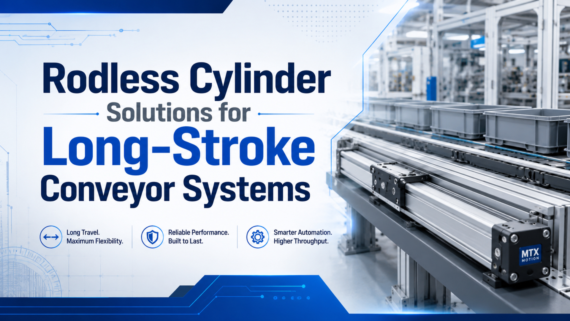
A rodless cylinder can be a strong fit for a long-stroke conveyor when the machine lacks room for an extending rod. Parker lists standard OSP-P strokes up to 6000 mm, but that number is only an envelope limit. The real selection still depends on payload offset, guide moments, cycle time, air flow, end-of-stroke energy, support spacing, and alignment (Parker, OSP-P Pneumatic Rodless Cylinders and Linear Guides, 2025).
This guide treats the conveyor as a moving system, not a catalog stroke. It shows which inputs belong in the duty sheet, how to compare a rodded alternative, and why a cylinder that passes the thrust calculation can still fail during acceleration or stopping.
A rodless conveyor axis is a pneumatic linear drive whose internal piston moves an external carriage along the cylinder profile. The carriage may use an integrated guide or connect through a floating bracket to a separate linear guide. This distinction matters because the pneumatic piston generates thrust. The guide carries the payload moments.
That separation drives the selection.
Key Takeaways
- Parker catalogs OSP-P strokes to 6000 mm, but long conveyor axes can need fixed and movable mid-section supports.
- Check thrust and guide moments separately.
- Cycle time controls valve flow demand; moving mass and impact speed determine the energy that must be absorbed.
- Measure dynamic pressure at the actuator.
The video demonstrates servo-pneumatic positioning. A conveyor that only needs two end positions may not need that control package, but the example makes one point visible: cylinder body, guide, sensor, valve, and controller must be treated as one motion axis.
When Is a Rodless Cylinder the Right Choice for a Long-Stroke Conveyor?
Choose a rodless cylinder when the conveyor needs long travel inside a compact machine envelope and the payload can be carried by a correctly sized carriage or external guide. Parker’s OSP-P range reaches 6000 mm and 8 bar, yet those catalog limits don’t approve the installed load path (Parker, OSP-P Series, 2026).
A rodded cylinder needs room for the cylinder body plus the extended rod. On a 4 m transfer, that can make the machine nearly twice the stroke length before guards, joints, and service access are added. A rodless cylinder keeps the moving interface beside the profile, so the actuator package stays close to the stroke length.
Stroke alone doesn’t choose the axis.
Space isn’t the only decision. Use a rodless axis when all of these statements are true:
- The required stroke and service clearance don’t fit a practical rodded layout.
- The selected carriage or external guide can carry the payload forces and moments.
- The valve, tubing, and plant air can deliver the target stroke time.
- The cushion or external stop can absorb the moving system’s energy.
- The machine frame can support the actuator without twist or excessive sag.
If the stroke is short, the load is guided elsewhere, and cost dominates, a standard cylinder may still be the simpler choice. The broader rodless-versus-standard cylinder comparison covers that architecture decision. This article stays with long-stroke conveyor duty.
Engineering insight: The useful threshold isn’t a fixed stroke such as 1000 mm. It is the point where the rodded package, buckling check, external guide, and guard become harder to justify than a supported rodless axis.
What Conveyor Duty Data Must Be Defined Before Sizing?
Start with a duty sheet, not a bore size. Parker catalogs eight OSP-P bores from 10 to 80 mm and theoretical forces from 47 to 3010 N at 6 bar, but none of those values describes payload offset, acceleration, or stopping (Parker, OSP-P Series, 2026).
Record the following inputs before comparing models:
| Input | What to record | Why it changes the selection |
|---|---|---|
| Travel | Working stroke, overtravel, sensor zones | Sets body length and support layout |
| Moving mass | Payload, carriage, bracket, cable carrier | Sets acceleration and stopping energy |
| Load offset | Distance from carriage center to payload center of gravity | Creates pitch, yaw, or roll moment |
| Orientation | Horizontal, vertical, inclined | Changes gravity and safe-failure behavior |
| Motion target | Stroke time, dwell, cycles per minute | Sets speed, flow, and thermal duty |
| Air condition | Pressure during motion, tube ID, tube length, valve flow | Determines available thrust and acceleration |
| Stop method | Air cushion, shock absorber, hard stop, controlled deceleration | Determines impact load and repeatability |
| Environment | Dust, washdown, temperature, clean area | Changes coupling, seal, cover, and material choices |
Measure pressure during conveyor motion. Static regulator pressure can look healthy even when the actuator inlet pressure collapses during peak flow. Also include the cable carrier, hose bundle, gripper, stop block, and any product that travels with the carriage. They all contribute mass or drag.
The drawing matters as much as the datasheet.
What if the payload changes by product size? State the minimum and maximum moving mass. A cylinder tuned for an empty carrier may hit the stop much harder when loaded. A valve selected for the loaded case may make the empty axis too abrupt.
In our experience, an application review should request load offset and pressure during motion before model matching. Bore and stroke alone can’t reveal the guide moment or the pressure available during acceleration, so those two missing inputs can stop a technically sound selection before it starts.
How Should Rodded and Rodless Cylinders Be Compared?
Compare both architectures at the same thrust, stroke, mounting, and safety factor. Euler’s relation makes critical buckling load proportional to 1/(K L)^2, so doubling unsupported rod length reduces the ideal critical load to one quarter before real-world imperfections are added (MIT OpenCourseWare, Structural Mechanics, 2013).
Do not use a universal shortcut such as “a rod buckles beyond 20 times its diameter.” Buckling depends on rod diameter, material modulus, mounting and rod-end conditions, unsupported length, compressive load, and the manufacturer’s safety method. A catalog stroke chart is the final authority for the selected rodded cylinder.
A universal stroke ratio can’t replace that chart.
| Check | Rodded cylinder | Rodless cylinder |
|---|---|---|
| Machine envelope | Body plus extended rod and service access | Body close to stroke length |
| Long-stroke structural concern | Rod buckling under compression | Tube support, carriage load, guide moment |
| Side load strategy | External guide should keep side load off the rod | Guided carriage or external guide must be rated |
| Force path | Piston to rod to joint to payload | Piston to coupling to carriage to payload |
| Main wear points | Rod seal, bearing, joint, external guide | Coupling or band, guide, carriage, seals, supports |
| Selection evidence | Buckling chart and mounting factor | Force, moment, support, speed, cushion data |
Rodless construction removes the exposed piston rod, not every long-stroke limit. Parker’s long-stroke OSP-P documentation requires a fixed mid-section support on its long-stroke series and may require additional movable supports according to stroke and load (Parker, OSP-P Long-Stroke Catalogue, 2026).
Load Path and Guide Moments
Guide capacity is separate from pneumatic force. SMC’s MY1 selection material divides mechanically jointed rodless cylinders into five guide families and prohibits excessive moment on the slide table. That structure shows why payload weight alone can’t approve a conveyor axis (SMC, MY1 Mechanically Jointed Rodless Cylinder, 2025).
Thrust answers one question: can air pressure accelerate the mass against friction and process resistance? Guide data answers another: can the carriage survive the forces and moments created by the payload position? Keep those calculations separate.
Thrust is only the first gate.
For a horizontal conveyor, an offset payload creates a moment approximately equal to load force multiplied by offset distance. Dynamic acceleration and deceleration add to that static value. The selected catalog may use Mx, My, and Mz, or pitch, yaw, and roll. Follow its coordinate system exactly.
SMC warns that an unsuitable mounting surface can twist the cylinder tube, damage sealing components, and cause malfunction. It also calls for intermediate support on long strokes to control sag, vibration, and external load (SMC, MY1B Specific Product Precautions, 2025).
The dedicated rodless cylinder load-capacity guide explains force and guide moments in more detail. Use it when the payload center of gravity is offset from the carriage.
From our work, a load sketch becomes useful only when it locates the payload center of gravity, guide centerline, stop, and support points on the same drawing. That simple geometry prevents the force calculation from being mistaken for a complete carriage-load approval.
How Much Flow Does the Target Stroke Time Require?
Size valve and tubing from target time, not port thread alone. CAGI says a well-designed compressed-air system should keep pressure drop from compressor discharge to point of use within 10%; long hoses, small valves, and restrictive fittings consume that margin (CAGI, Technical Brief on Pressure Drop, 2026).
The first-pass sequence is straightforward:
- Calculate piston area from bore.
- Multiply area by stroke to obtain chamber volume.
- Convert cylinder volume to normalized free-air volume using absolute pressure ratio.
- Divide that air quantity by target stroke time.
- Add tubing volume, dead volume, leakage, temperature, and control margin.
- Verify dynamic pressure and actual stroke time on the machine.
For illustration, a 63 mm bore and 4000 mm stroke has about 12.47 L of geometric chamber volume. At 6 bar gauge, an ideal one-way fill is about 87.28 normal liters when approximated with a 7:1 absolute-pressure ratio. Real demand will be higher once line volume, exhaust behavior, and losses are included.
The port label doesn’t answer this demand.
Worked-example insight: A long-stroke conveyor can be force-safe and still cycle too slowly. That is why changing bore without checking flow sometimes makes the result worse. The larger chamber demands more air, but the original valve and tube remain the bottleneck.
Use the rodless cylinder proportional-flow-control guide when the motion needs more than fixed meter-out adjustment. For general air-system faults, the pressure-drop troubleshooting guide covers filters, fittings, hoses, and distribution piping.
Stopping Energy and Cushioning
Stopping demand rises with speed squared. SMC lists maximum energy absorption of 5.9, 19.6, and 58.8 J for three MY1B shock absorbers, and requires each application to stay inside the absorption-capacity range (SMC MY1B, 2025).
Start with translational kinetic energy:
Kinetic energy = 0.5 x moving mass x impact velocity^2Then add any thrust energy that acts during the stopping distance, plus gravity for a vertical or inclined axis. Use velocity at cushion entry or stop impact, not average stroke speed. The selected cylinder or shock-absorber catalog defines its own calculation method and allowable range.
Speed is expensive at the stop.
Don’t assume a larger bore solves an impact problem. A larger cylinder can add carriage mass and thrust energy. Better options may include a longer deceleration distance, lower impact speed, external shock absorbers, a controlled stop, or a different motion profile.
The pneumatic cylinder cushioning guide covers cushion adjustment and failure symptoms. The separate air-cushion guide for high-speed applications explains why average speed alone isn’t enough.
Which Rodless Cylinder Construction Fits the Conveyor?
Choose coupling and guide from environment and load path, not stroke alone. SMC lists MY1B at 0.1 to 0.8 MPa and 100 to 1000 mm/s, with options up to 1500 mm/s (SMC MY1B, 2025).
Use the construction table as a screening tool:
| Construction | Useful conveyor fit | Main checks |
|---|---|---|
| Magnetically coupled | Clean travel, moderate coupling demand, closed tube | Magnetic decoupling force, debris attraction, load guide |
| Mechanically coupled band type | Higher force transfer and common industrial layouts | Seal band protection, contamination, carriage guide, leakage |
| Basic rodless cylinder with external guide | Machine already has a qualified linear guide | Alignment between actuator and guide, floating connection |
| Integrated guided rodless cylinder | Payload mounts directly to carriage | Allowable forces and moments, guide life, mounting flatness |
| Servo-pneumatic package | Variable positions or motion profiles | Feedback, valve flow, tuning, safe stop, control architecture |
A magnetic design isn’t automatically a cleanroom solution, and a mechanical design isn’t automatically heavy-duty. Check the exact catalog, sealing arrangement, guide, and environment rating. If the conveyor carries abrasive dust, liquid, or metal chips, protect the sealing band and guide or choose a construction intended for that exposure.
The coupling doesn’t carry every load.
The guide to rodless pneumatic cylinder types explains the construction families. If the machine only needs a definition and basic mechanism, use the rodless cylinder fundamentals article instead of repeating that material here.
Installation and Commissioning Checks
Long-stroke installation needs support and alignment evidence. SMC requires at least 5 mm of contact at each cylinder end in its MY1B precautions and calls for intermediate support on long strokes. Parker likewise publishes load-versus-support-spacing charts for its long-stroke OSP-P family (SMC, MY1B Precautions, 2025).
Before applying air:
- Check the machine frame and mounting surface for level, flatness, and twist.
- Install the specified fixed and intermediate supports without forcing the profile into alignment.
- Confirm the carriage can move through the full stroke without binding.
- Route tubing and the cable carrier so they don’t add side pull or snag at the ends.
- Set sensors with enough margin for stopping distance and control response.
- Start at reduced pressure and speed, then increase duty in controlled steps.
- Measure pressure at the actuator during the fastest part of the cycle.
- Record full-load and empty-carrier stroke times, cushion behavior, and stop repeatability.
During maintenance, isolate more than the electrical supply. OSHA’s 29 CFR 1910.147 applies to pneumatic energy and requires hazardous stored or residual energy to be relieved, disconnected, restrained, or otherwise made safe before servicing (OSHA, Control of Hazardous Energy, 2026).
One commissioning run isn’t enough. Test the heaviest payload, the lightest payload, cold start, normal operating temperature, and the lowest expected supply pressure. Why test both load extremes? The heavy case challenges thrust and stopping capacity. The light case can expose abrupt acceleration and bounce.
A straight axis should move freely by hand.
We found that commissioning records are easiest to compare when each run captures moving mass, dynamic inlet pressure, stroke time, cushion setting, and stop behavior together. A speed number without those conditions can’t show whether a later change came from air supply, payload, or adjustment.
What Should the RFQ Include?
A useful RFQ contains more than bore and stroke. Parker’s OSP-P family spans 10 to 80 mm bores and 47 to 3010 N theoretical force at 6 bar, so two cylinders with the same 4000 mm stroke can serve very different duties (Parker, OSP-P Series, 2026).
Send this information:
- Identify the existing manufacturer, complete model code, working stroke, acceptable overall length, port orientation, and mounting geometry. Add photos when replacing a cylinder.
- Define orientation, minimum and maximum moving mass, carriage hardware, and the payload center-of-gravity offset in every relevant direction.
- State extend and retract times, dwell, cycles per minute, pressure measured during motion, valve flow, tube inside diameter, and tube length.
- Describe the internal cushion, external shock absorber, brake, hard stop, sensors, PLC voltage, and every required stopping position.
- Document dust, washdown, temperature, corrosion, cleanliness, support locations, cable routing, and the old system’s failure symptoms.
Conditions give the numbers meaning.
RFQ insight: An RFQ becomes engineering-ready when every number has a location and operating condition. “20 kg load” is incomplete. “20 kg moving mass, center of gravity 120 mm above the carriage, horizontal travel, 4 m stroke, 4 s move, 6 bar dynamic inlet pressure” can be checked.
Use this final decision rule: select the architecture by machine envelope, the bore by dynamic thrust, the guide by combined forces and moments, the valve and tube by stroke time, the stop by energy, and the supports by span and load. No single catalog number replaces that chain.
FAQs About Rodless Cylinder Solutions for Long-Stroke Conveyors
Answers keep limits separate. Parker publishes 6000 mm for OSP-P; SMC lists 100 to 1000 mm/s for MY1B. Neither value should transfer to another series without its current catalog (Parker, 2026; SMC, 2025).
What is the maximum stroke for a rodless conveyor cylinder?
Parker lists a 6000 mm maximum stroke for its OSP-P family, with longer or special long-stroke arrangements handled separately. That is model-specific, not a universal rodless-cylinder limit. Confirm bore, support spacing, carriage load, guide moment, speed, cushioning, and the supplier’s current order code before treating 6000 mm as an approved conveyor stroke.
Can a rodless cylinder carry the conveyor payload directly?
Only when its carriage guide is rated for the combined load and moments. Parker lists theoretical OSP-P force from 47 to 3010 N at 6 bar, but thrust doesn’t prove guide capacity. Include payload weight, center-of-gravity offset, acceleration, deceleration, orientation, external stops, and cable-carrier forces in the selected model’s guide calculation.
Do long rodless cylinders need intermediate supports?
They often do. SMC instructs users to add intermediate support on long MY1B strokes to control tube sag, vibration, and external load. Parker publishes support-spacing charts for long-stroke OSP-P models. Use the selected series’ chart and don’t force a bowed profile straight with support brackets, because that can create binding or leakage.
How fast can a rodless conveyor cylinder run?
Speed is model and load dependent. SMC lists 100 to 1000 mm/s for the referenced MY1B basic configuration and allows up to 1500 mm/s with specified adjustment units and conditions. The final limit must also pass valve-flow, pressure-drop, guide, impact-speed, cushion-energy, sensor, and conveyor-product stability checks.
Does stroke tolerance equal conveyor positioning accuracy?
No. SMC lists stroke-length tolerance of approximately +2.0/-0.8 mm for referenced MY1B strokes from 2701 to 5000 mm, but that is a manufacturing dimension, not positioning repeatability. Conveyor accuracy also depends on sensor location, stop compliance, load variation, pressure, valve response, guide clearance, controller behavior, and thermal expansion.
Source notes and retrieval details
-
Parker, OSP-P Pneumatic Rodless Cylinders and Linear Guides, 2025. Used for standard stroke range and OSP-P construction. Retrieved 2026-07-10.
-
Parker, OSP-P Series technical specifications, 2026. Used for bore range, 6000 mm maximum stroke, 8 bar maximum pressure, and force range at 6 bar. Retrieved 2026-07-10.
-
Parker, OSP-P Long-Stroke Linear Drive System Catalogue, 2026. Used for fixed and movable mid-section support requirements. Retrieved 2026-07-10.
-
SMC, MY1B Mechanically Jointed Rodless Cylinder Basic Type, 2025. Used for pressure, speed, stroke tolerance, cushion, and shock-absorber data. Retrieved 2026-07-10.
-
SMC, MY1B Specific Product Precautions, 2025. Used for mounting contact, intermediate support, alignment, twist, and slide-table moment precautions. Retrieved 2026-07-10.
-
MIT OpenCourseWare, Structural Mechanics Lecture 10, 2013. Used for Euler column-buckling behavior and length sensitivity. Retrieved 2026-07-10.
-
CAGI, Technical Brief on Pressure Drop, current technical brief. Used for the 10% point-of-use pressure-drop guideline. Retrieved 2026-07-10.
-
OSHA, Lockout-Tagout Scope and Application, current regulation guidance. Used for pneumatic-energy isolation and 29 CFR 1910.147 scope. Retrieved 2026-07-10.
-
Enfield Technologies, Better Rodless Positioning. Used only as a practical position-control demonstration. Video title and channel verified through YouTube oEmbed; thumbnail returned HTTP 200. Retrieved 2026-07-10.