

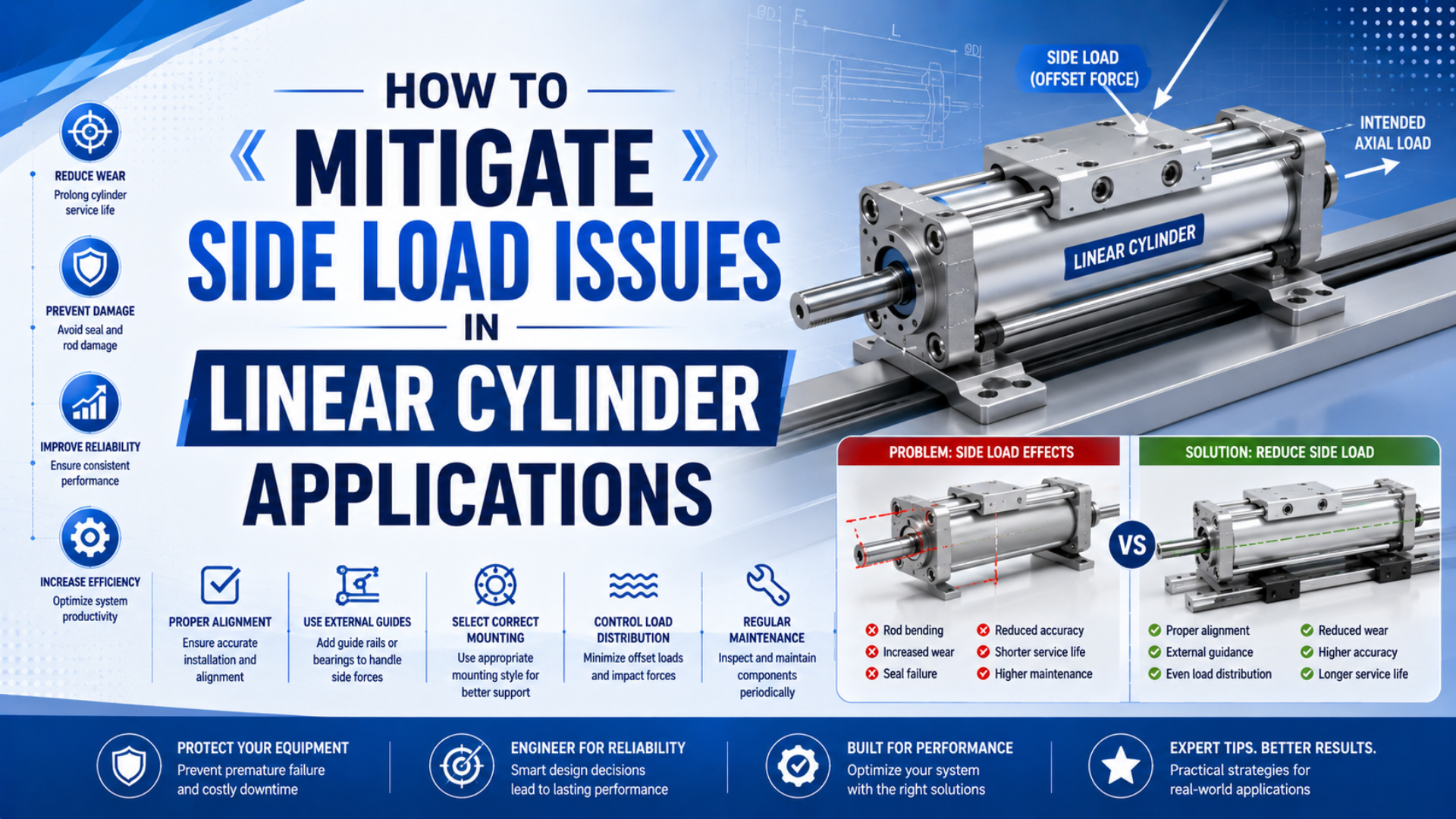
Mitigate a linear cylinder side load by separating guidance from thrust, measuring the load-center offset, checking every force and moment against the exact catalog, and correcting mounting alignment before replacing the actuator. A larger bore can add axial force, but it does not automatically fix rod-bearing load, carriage moment, structural deflection, or an over-constrained mechanism.
Festo’s 2026 DSBC catalog shows why generic side-load ratings are unsafe: one 32 mm protected-rotation example permits 9.5 N at a 150 mm stroke, yet the allowable value changes with stroke and lever arm (Festo DSBC catalog, 2026, retrieved 2026-07-10). Treat the cylinder, guide, tooling, mount, and stop as one load path.
Key Takeaways
- Festo’s worked 32 mm example permits 9.5 N, not a universal rating.
- External guides carry lateral force and moment; the cylinder supplies axial thrust.
- Before restart, check alignment unloaded and loaded at retracted, mid-stroke, and extended positions, then verify deceleration at production mass and speed against the configured guide and cushion limits.
For suspended loads, safety-critical axes, or missing center-of-gravity data, confirm the load case with drawings before specifying hardware.
Side-load problems are usually load-path problems.
What Is Side Load in a Linear Cylinder?
Side load is any force perpendicular to the intended stroke axis, and its effect grows when the force acts through an offset. Festo’s 2026 DSBC example pairs a 150 mm stroke with an 84 mm lever arm and permits 9.5 N, proving that force, stroke, and geometry must be checked together (Festo DSBC catalog, 2026, retrieved 2026-07-10).
The basic moment relationship is simple:
M = Fq x s
Mis the bending or guide moment that the selected bearing, carriage, mounting structure, and fasteners must resist.Fqis the transverse force.sis the perpendicular distance from the supported centerline to the load.
Load moment is the turning effect created when transverse force acts through an offset. That distance is easy to miss. For example, a tooling plate can keep the same weight after a redesign but create a larger moment because its center of gravity moved farther from the guide. Why did a previously stable axis begin wearing one side of the rod seal? The new bracket geometry may matter more than the cylinder bore.
From our analysis of Festo’s worked examples, we found that 9.5 N x 84 mm and 8 N x 100 mm both approach the same 800 Nmm torque limit. The comparison makes offset visible: reducing transverse force isn’t enough when the bracket moves its line of action farther from the supported centerline.
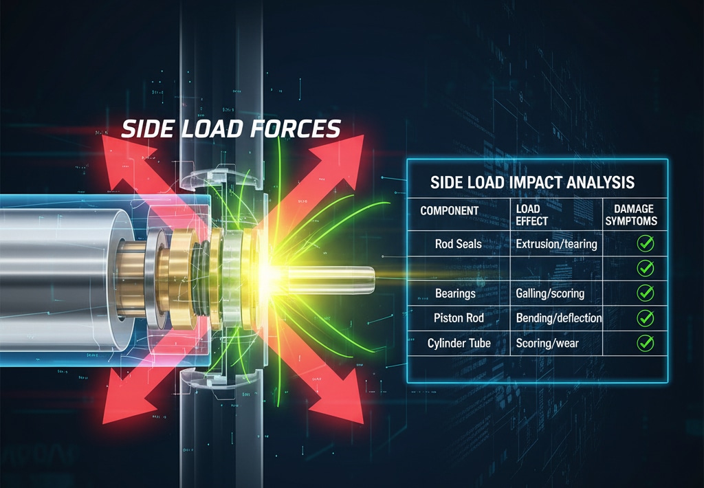
The legacy illustration is qualitative. It identifies affected components but does not provide a universal side-load rating.
How Side Loads Damage Rods, Bearings, and Seals
Side loading first changes contact pressure and alignment, then wear becomes visible at the rod gland, bearing, guide, or tube. Parker’s cylinder safety guide requires alignment checks in 2 positions, fully extended and fully retracted, because poor alignment produces excessive rod-gland or bore wear (Parker Cylinder Safety Guide, retrieved 2026-07-10).
Wear location is a clue, not a verdict.
The symptom alone doesn’t identify the cause. For example, a leaking rod seal may be worn, but replacing it without correcting alignment only resets the clock. Rough travel can come from a skewed external rail, a bent bracket, unequal guide preload, contaminated bearings, or a cylinder mount that moves under load.
| Symptom | Side-load mechanism to check | Evidence to collect before repair |
|---|---|---|
| Seal wear concentrated on one side | Rod or carriage is being pushed off center | Seal pattern, rod witness marks, load direction |
| Scored rod or gland | Bearing contact pressure is too high | Surface marks at full extension and retraction |
| Motion is smooth unloaded but binds loaded | Structure or guide deflects under payload | Indicator readings unloaded and loaded |
| Harsh stop followed by new leakage | Dynamic force exceeds cushion, guide, or mount capacity | Moving mass, speed, stop position, cushion setting |
| Repeated bolt movement | Mount is carrying a moment it was not designed to resist | Dowel, key, bolt torque, frame stiffness |
Static and dynamic failures leave different evidence. An axis that binds while parked points toward geometry, preload, gravity load, or structural distortion. Binding only during acceleration or stopping calls for measurements of speed, pressure during motion, load offset, and cushion behavior, not another photograph taken at rest.
How Do You Diagnose the Load Path?
Diagnose the complete load path, not one component at a time. Festo’s 2026 DGC catalog requires 5 normalized terms, Fy, Fz, Mx, My, and Mz, to sum to no more than 1 when they act together; it also warns that deceleration needs special attention (Festo DGC catalog, 2026, retrieved 2026-07-10).
Use the configured model’s coordinate system. Do not assume every supplier defines axes and positive directions the same way.
Fy/Fymax + Fz/Fzmax + Mx/Mxmax + My/Mymax + Mz/Mzmax <= 1
- Sketch every mechanical datum.
- Mark gravity, process force, cable drag, hose reaction, acceleration, and stop force.
- Measure each perpendicular offset to the selected bearing or carriage center.
- Calculate static moments, then repeat the check for acceleration and deceleration.
- Compare every individual term and the combined ratio with the exact catalog revision, configured guide type, motion direction, travel speed, and deceleration condition.
A load-path sketch often finds the problem before a force calculation does. If the drawing shows the cylinder rod supporting tooling weight, the architecture is already asking a thrust component to work as a linear bearing. Move that reaction into a guide before increasing the bore.
A force number without geometry isn’t a usable rating.
For a deeper rodless-carriage calculation, use the rodless cylinder load-capacity guide. It covers pitch, roll, yaw, stopper energy, and model-specific combined-load checks without turning this retrofit article into another general sizing guide.
Why Should External Guidance Carry the Lateral Force?
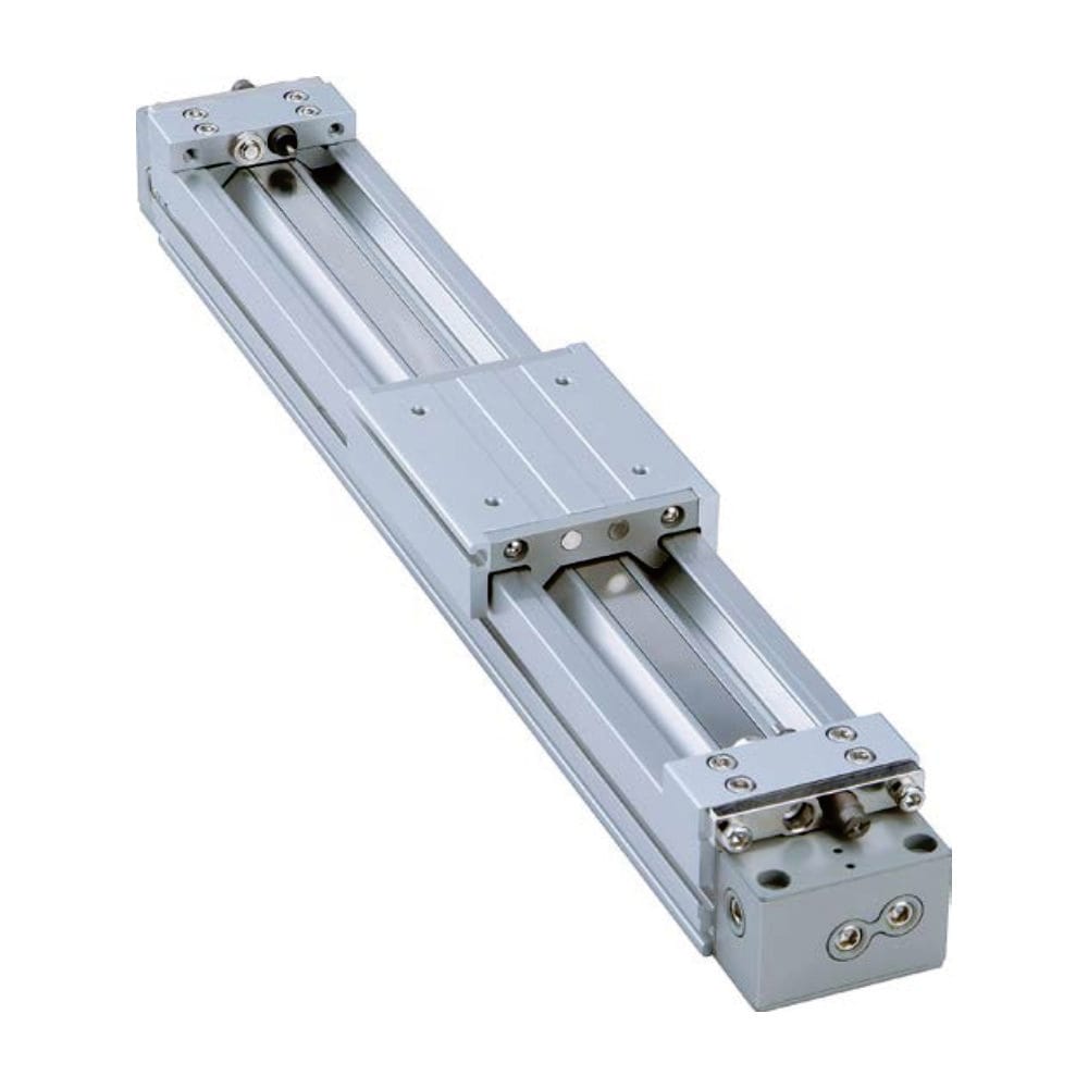
External guidance is the bearing system that should carry lateral force while the cylinder supplies centerline thrust. SMC’s current MGQ guided-cylinder range integrates guidance across 10 listed bore sizes from 12 to 100 mm, showing that lateral-load resistance is a defined product architecture rather than a generic feature of every cylinder (SMC Web Catalog, retrieved 2026-07-10).
The guide, not the seal, owns that reaction.
A standard rod cylinder can work well with an external linear guide when the guide supports weight and moment independently. The connection between the rod and guided tooling should transmit axial force without forcing two imperfectly aligned bearing systems to fight each other.
| Layout | Where thrust is generated | Where side load and moment should go | Selection caution |
|---|---|---|---|
| Standard rod cylinder plus rail | Piston and rod | External rail and carriage | Keep rod and rail parallel through full stroke |
| Compact guided cylinder | Piston | Integrated guide rods or bearings | Use the exact lateral-load and torque curves |
| Guided rodless cylinder | Internal piston and carriage coupling | Integrated carriage guide | Check combined forces, moments, speed, and stop energy |
| Basic rodless cylinder plus external guide | Internal piston and carrier | Separate rail | Use a tolerant carrier connection to avoid over-constraint |
The rodless versus standard cylinder comparison helps when installed length and rod buckling also affect the decision. For construction differences among magnetic, slotted, cable, and guided designs, see the rodless cylinder types guide.
Which Mounting Style Prevents Binding?
The correct mount follows the real motion and keeps major force near the cylinder centerline. Parker groups roughly 20 standard single-rod mounting styles into 3 force-transfer families: centerline fixed, pivot, and non-centerline fixed mounts (Parker Catalog 0900P-6, Mounting Information, retrieved 2026-07-10).
Mounting hardware cannot rescue a mechanism with the wrong motion model.
Use a centerline fixed mount when the driven member truly moves in a straight line. Flanges and centerline lugs keep push or pull symmetric around the cylinder axis. Side-mounted bodies need a rigid machine member and the manufacturer’s recommended keying or doweling when shock can shift the mount. Use a pivot mount when the load follows an arc. Parker states that clevis and trunnion mounts are intended for motion in one plane. Its catalog recommends a spherical bearing mount when rod travel stays within 3 degrees on either side of that true plane; outside the accessory’s limit, review the joint and bearing again. The mount must also match whether the dominant load is push or pull, since flange orientation changes bolt and flange stresses. Finally, verify the frame carries the same reaction without twisting the cylinder datum under load.
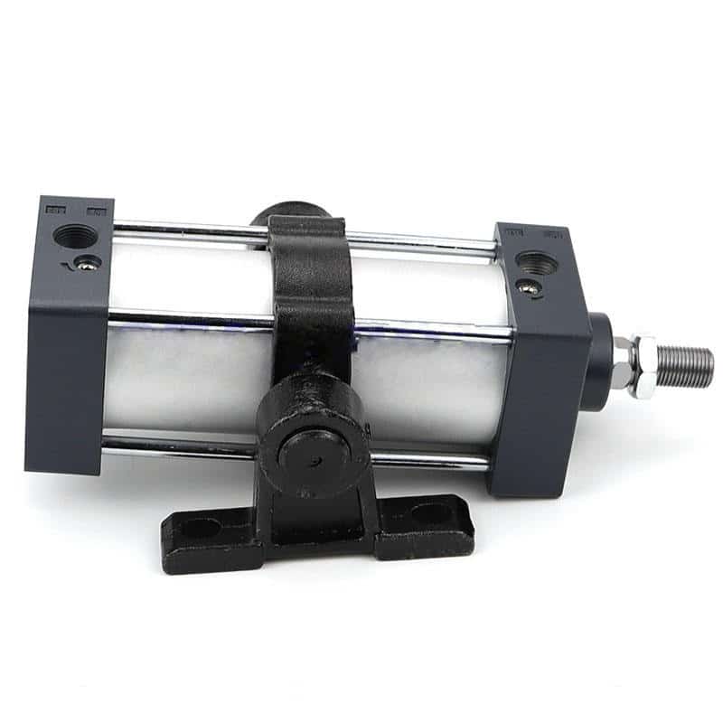
Parker also notes that trunnion pins are designed for shear, not bending. Support bearings should be rigid, aligned, and at least as long as the pins. A trunnion photo does not prove a safe installation; the support spacing, load direction, and true pivot plane decide whether the mount reduces side load or introduces it.
| Motion path | Appropriate starting point | Common side-load mistake |
|---|---|---|
| Straight, centerline push or pull | Fixed centerline mount | Mounting the body off-center on a flexible plate |
| Arc in one plane | Clevis or trunnion | Locking the rod end so it cannot follow the arc |
| Small angular and radial mismatch | Rated spherical bearing or alignment coupler | Treating the accessory as a structural guide |
| Curved motion in more than one plane | Purpose-designed multi-axis joint | Forcing a single-plane clevis through compound motion |
How Do Flexible Couplings Help With Misalignment?
A self-aligning coupling is a force-transfer accessory that prevents small assembly errors from becoming bearing loads; it does not support the payload. Festo’s 2026 DSBC table separates 3 functions: FK handles radial and angular deviation, KSG handles radial deviation, and a rod clevis permits swivel in one plane (Festo DSBC catalog, 2026, retrieved 2026-07-10).
Compliance needs a defined job and rated travel.
Choose the accessory from its permitted movement, tensile or compressive rating, thread, pressure limitation, and installation instructions. The joint may absorb a small offset. It cannot turn an unsupported 40 kg fixture into an acceptable rod load.
What if the flexible joint reaches the end of its travel during every cycle? That isn’t compensation anymore. The mechanism is using the coupling as a stop, so the load path, guide position, or mounting geometry needs correction. Check for over-constraint as well. Two parallel guides with different datums can bind even when each guide passes its own catalog calculation. Define one primary guide, provide controlled compliance at the force-transfer joint, and avoid adding a second rigid locator without a tolerance analysis. Before release, measure the coupling position at both ends and mid-stroke; rated articulation should remain available in both directions instead of bottoming against one side. Document the centered position so future maintenance can separate joint wear from a new alignment shift.
Verification Before Restarting Production
Verify the repair without exposing people or hardware to full-speed motion. Parker’s OSP-P instructions specify 2 manual strokes without air pressure, then the entire moving zone at low speed, followed by slow pressurization and cushion adjustment (Parker OSP-P Operating Instructions, 2019, retrieved 2026-07-10).
Before hands enter the machine, isolate every energy source. OSHA 29 CFR 1910.147 covers servicing where unexpected startup or release of stored pneumatic, mechanical, electrical, or other energy could injure an employee (OSHA 1910.147, retrieved 2026-07-10). Follow the machine’s validated energy-control procedure and applicable local requirements.
We analyzed Parker’s commissioning sequence as a load-path test, not a startup shortcut. Use this sequence after the side-load correction:
- Lock out energy, release stored pressure, block gravity loads, and verify the safe state before anyone enters the hazard zone.
- Disconnect the rod or carrier if required, then move the guide and load by hand through the full stroke.
- Make two permitted manual strokes without air pressure.
- Reconnect the load without using the fasteners to pull either component into alignment.
- Measure parallelism and offset at retracted, mid-stroke, and extended positions.
- Pressurize slowly and start at low speed; watch the complete motion zone for collision, stick-slip, bolt movement, changing clearance, hose pull, or guide deflection.
- Tune cushioning, then verify dynamic force and moment at production payload and speed using the configured guide limits, stop-energy data, and acceptance measurements recorded before release.
A smooth empty cycle is only the first gate.
Record unloaded and loaded indicator readings at the same stroke positions. The difference exposes structural deflection that a static alignment check can hide. If the axis is aligned empty but moves out of line under payload, replacing seals or increasing supply pressure won’t correct the frame.
For the detailed relationship among moving mass, velocity, and end energy, use the pneumatic cylinder cushioning guide.
What Should Go Into a Side-Load Retrofit RFQ?
A retrofit RFQ needs geometry and operating data, not only bore and stroke. ISO 15552 covers interchangeable mounting dimensions for 32 to 320 mm bores at a maximum rated 1,000 kPa, but the standard does not create a universal side-load allowance (ISO 15552:2018, confirmed 2025, retrieved 2026-07-10).
A model number is only the starting point.
Send one marked-up drawing and one operating table. State which values are measured, calculated, assumed, or copied from the current nameplate.
Geometry and Duty Inputs
| RFQ input | What to record | Why it changes side-load risk |
|---|---|---|
| Cylinder identity | Manufacturer, full model, bore, stroke, rod, mount | Connects the review to the correct catalog |
| Payload | Mass, center of gravity, bracket drawing | Defines gravity force and moment arms |
| Motion | Orientation, stroke time, cycles, dwell, acceleration | Separates static from dynamic loading |
| Pressure and flow | Pressure during motion, valve, tube size, exhaust control | Distinguishes low thrust from mechanical binding |
Integration and Evidence Inputs
| RFQ input | What to record | Why it changes side-load risk |
|---|---|---|
| Guidance | Rail model, carriage spacing, preload, lubrication | Defines lateral-force and moment capacity |
| Connections | Rod-end joint, clevis, spherical bearing, coupler | Shows where compliance or constraint enters |
| Stops | Cushion type, shock absorber, hard stop, stop position | Defines deceleration force and guide moment |
| Evidence | Wear photos, indicator readings, failed-part history | Tests whether the proposed fix addresses the cause |
Use the pneumatic cylinder theory guide for axial force and pressure-area fundamentals. Keep that force calculation separate from the transverse-force and guide-moment review.
FAQs About Side Load Mitigation
No universal percentage exists. Festo’s 2026 DGC catalog checks 5 simultaneous force and moment terms, with a normalized sum no higher than 1. Keep answers tied to the configured model, guide, stroke, orientation, speed, and deceleration condition instead of a site-wide rating (Festo DGC catalog, 2026, retrieved 2026-07-10).
Catalog limits beat generic percentages every time.
How much side load can a pneumatic cylinder handle?
Use the exact model’s lateral-force, stroke, lever-arm, and mounting data. Festo’s 2026 DSBC catalog permits 9.5 N in its 32 mm, 150 mm stroke example, but that is not a generic rating. Change the offset, guide option, speed, or orientation and the allowable value can change.
Will a larger piston rod solve a side-load problem?
Not by itself. A larger rod can improve stiffness or buckling margin, but it doesn’t align a skewed guide or remove an offset moment. ISO 15552:2018 spans 32 to 320 mm bores, yet standardizes dimensions rather than one side-load value. Correct the load path before sizing the configured rod and bearings.
Can a self-aligning coupling replace an external guide?
No. Festo’s 2026 DSBC catalog separates 3 accessory functions: FK handles radial and angular deviation, KSG handles radial deviation, and a rod clevis swivels in one plane. These parts reduce assembly stress. Payload weight, pitch, roll, yaw, and process force remain guide loads requiring a model-specific calculation.
When should I choose a guided cylinder?
Choose one when the actuator must resist a defined lateral load or torque within a compact assembly and its catalog limits cover the duty. SMC’s current catalog lists MGQ guided cylinders in 10 bore sizes from 12 to 100 mm. Also check bearing type, stroke, orientation, moment, speed, stop energy, and environment.
How should I test a side-load retrofit?
Follow the machine’s energy-control procedure first. Parker’s OSP-P instructions call for 2 manual strokes without pressure, full-zone travel at low speed, slow pressurization, and cushion adjustment. Add loaded alignment readings at retracted, mid-stroke, and extended positions. Stop if clearance, bolt position, or indicator readings change unexpectedly.