

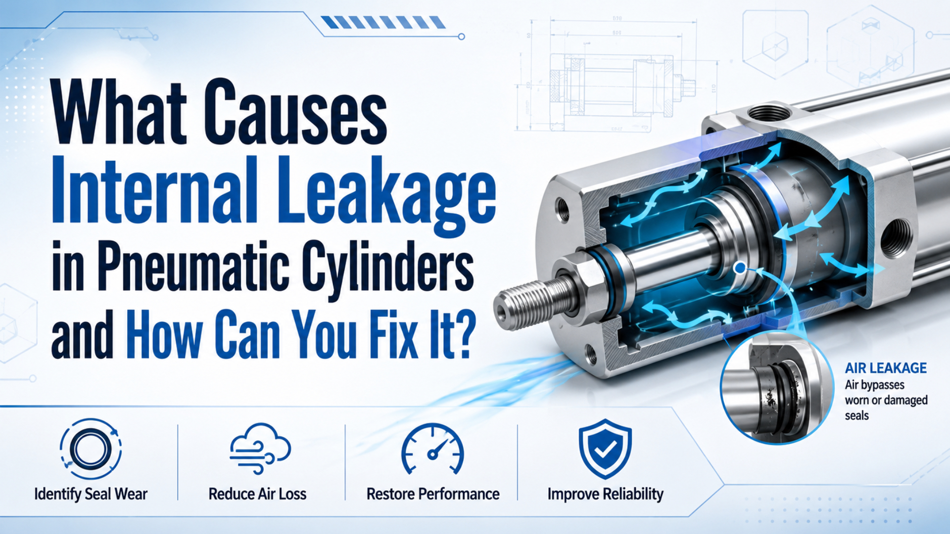
Internal leakage in a pneumatic cylinder is air bypassing the piston seal from the pressurized chamber into the opposite chamber. It isn’t the same as a rod-seal leak to atmosphere. Parker’s pneumatic cylinder guidance allows 1 to 3 cubic inches per minute for piston-ring construction but expects virtually no static leakage from lip-seal pistons, which shows why one universal percentage is the wrong acceptance test (Parker Hannifin Pneumatic Actuator Products, accessed 2026).
The fix starts with diagnosis. Separate the cylinder from the valve and supply circuit, compare the measured leakage with the exact cylinder specification, then inspect the piston seal, bore, guide surfaces, alignment, air quality, and speed-control settings. Replacing a seal without finding what damaged it often buys only a short pause.
Key Takeaways
- Acceptable internal leakage depends on seal construction and the cylinder model, not a universal 1 to 2 percent rule.
- Drift alone doesn’t prove piston bypass; valve leakage, pressure drop, exhaust restriction, or mechanical binding can create similar symptoms.
- Measure both directions, inspect the bore and guides, and verify the repair against a recorded baseline.
Use primary technical and safety sources when diagnosing internal leakage; model-specific questions should include cylinder photos, pressure readings, leak-rate evidence, and valve information.
What Counts as Internal Leakage in a Pneumatic Cylinder?
Piston bypass is chamber-to-chamber flow across the piston sealing interface. Parker gives a construction-specific limit of 1 to 3 in3/min for piston rings while expecting virtually no static leak from piston lip seals. Therefore, the cylinder’s seal design and service manual must define pass or fail (Parker Hannifin Pneumatic Actuator Products, accessed 2026).
That definition creates a clean diagnostic boundary. A worn piston seal, scored bore, damaged piston, or failed static seal around the piston assembly can let air cross from one working chamber to the other. The leak may then leave through the opposite valve port or exhaust path, but its origin remains inside the cylinder. Rod-seal leakage is different. It escapes around the piston rod to atmosphere. A loose fitting, cracked tube, end-cap seal, or port seal also creates external leakage. Valve spool leakage happens inside the control valve. Each fault can waste air or weaken motion, but each one needs a different repair.
| Leakage or loss path | Where the air moves | Typical evidence | First isolation step |
|---|---|---|---|
| Piston seal bypass | One cylinder chamber to the other | Drift, weak hold, flow at the opposite port | Separate the cylinder from the valve test |
| Rod-seal leakage | Working chamber to atmosphere at the gland | Hiss, detectable flow, contamination around the rod | Inspect rod, gland, wiper, and rod seal |
| Valve internal leakage | Supply or work port to exhaust inside the valve | Cylinder drifts only when connected to the valve | Cap or test the cylinder with an approved manifold |
| Supply pressure loss | Header to cylinder inlet during flow | Normal static gauge, low pressure during motion | Measure both sides of the restriction |
| Exhaust restriction | Cylinder chamber cannot vent fast enough | Slow or jerky motion without a hold leak | Check muffler, meter-out valve, and exhaust path |
The useful diagnostic question isn’t simply, “Is the cylinder leaking?” Ask which boundary the air crossed: piston, rod gland, valve, supply path, or exhaust path. That distinction prevents a piston seal from being blamed for a valve or piping problem.
For the broader sealing-system view, including rod seals, wipers, wear rings, and static seals, use the pneumatic cylinder sealing systems guide. This article stays focused on internal piston bypass.
Why Does Air Bypass the Piston Seal?
Air bypasses the piston when the seal loses contact or the bore develops a leak path. Festo notes that one cubic meter of untreated ambient air can contain up to about 180 million particles from 0.01 to 100 micrometers, and lists damaged sealing surfaces and internal leakage among the resulting pneumatic risks (Festo compressed air contamination guidance, accessed 2026).
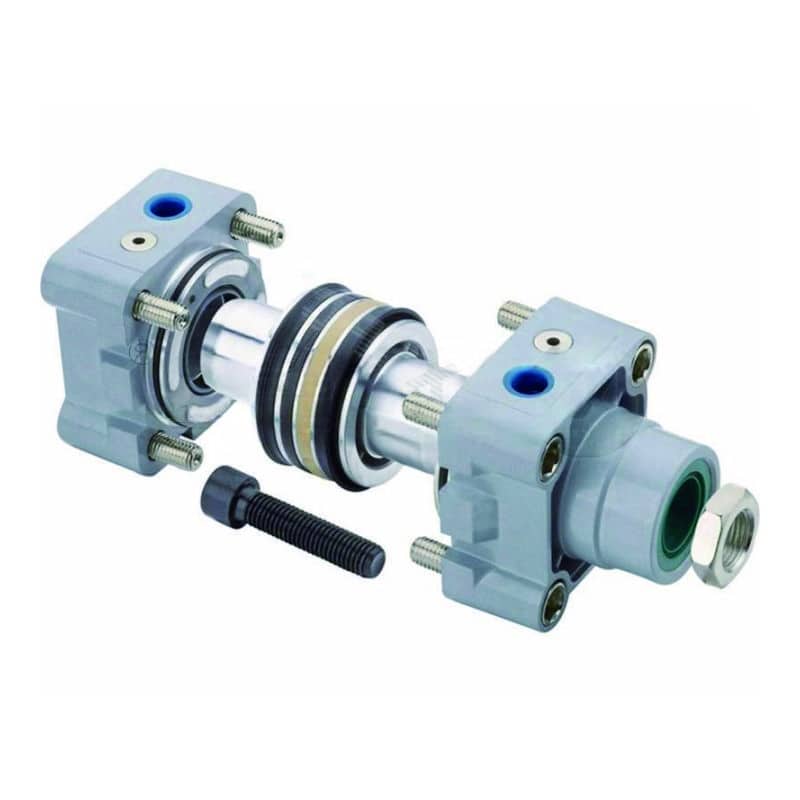
The common causes form a chain rather than a random list:
- Piston seal wear: Repeated sliding slowly changes the lip, ring, or energized profile until it can no longer maintain contact.
- Bore scoring or corrosion: A longitudinal scratch creates a direct channel across the sealing line. Rust can damage both the bore and the replacement seal.
- Contaminated compressed air: Particles abrade the bore and piston seal. Water encourages corrosion, while incompatible oil can swell or degrade elastomers.
- Side load and misalignment: Worn guides or a misaligned load tilt the piston, concentrating wear on one side of the seal and bore.
- Wrong seal, groove, or orientation: A visually similar seal can have the wrong profile, squeeze, pressure direction, or material.
- Installation damage: Sharp threads, dry assembly, dirty benches, and pinched lips can damage a new seal before the first production cycle.
- Temperature or chemical mismatch: Parker’s guide links hard or inelastic standard seals with exposure above 165 degrees F, or 74 degrees C, and recommends matching the material to the actual service environment (Parker Hannifin Pneumatic Actuator Products, accessed 2026).
ISO 8573-1 classifies compressed-air purity by particles, water, and oil. It doesn’t prescribe one purity class for every cylinder, but it gives maintenance teams a common way to specify the air delivered to the machine (ISO 8573-1:2010, 2010). Connect repeated piston-seal failures to the ISO air-quality guide instead of ordering the same kit again.
What does the old seal tell you?
One-sided polish points toward alignment or guide wear; a cut lip suggests installation damage or a sharp edge.
Swelling points toward chemical or lubricant incompatibility. A matching score line on both seal and bore makes a seal-only repair hard to justify.
For example, a fresh piston seal can leak again within the same bore if a longitudinal scratch remains under the sealing lip. The repeated leak doesn’t prove the replacement seal was poor. It proves the running surface was part of the failure.
How Does Internal Leakage Affect Force and Air Demand?
Internal leakage reduces the pressure difference that creates cylinder force, but the loss isn’t a universal percentage. CAGI shows that a stroke using 1 cubic foot at 80 psig consumes 1.21 cubic feet at 100 psig, so raising pressure to mask motion loss can increase air demand by 21 percent (CAGI Working With Compressed Air, accessed 2026).
The working relationship is:
Available cylinder force = pressure difference across piston x effective area - frictionDynamic pressure is pressure measured while the cylinder is moving or holding its real load.
The pressure difference across the piston matters more than the compressor-room gauge. If one chamber is at 6 bar and the opposite chamber is near atmosphere, the actuator has a large useful differential. If bypass or trapped exhaust raises the opposite pressure, useful force falls.
This is why a leak percentage cannot be converted directly into a force-loss percentage.
Seal geometry, valve state, exhaust back pressure, bore, rod area, speed, load direction, and control timing all influence the result. Measure both chamber pressures during the fault before calculating available force.
Air demand also depends on the circuit. Piston bypass may flow into a chamber that is vented through the valve, creating continuous consumption during a hold. In another valve state, pressure may equalize and the actuator may drift without the same continuous exhaust flow. A flow meter or controlled decay test is stronger evidence than a generic energy-cost multiplier. The U.S. Department of Energy reports that whole-system leaks can waste 20 to 30 percent of compressor output in poorly maintained plants (DOE Improving Compressed Air System Performance, 2003). That plant-level figure includes fittings, hoses, valves, drains, and other atmospheric leaks. Don’t assign all of it to cylinder piston bypass.
How Can You Confirm the Cylinder Is Leaking Internally?
Confirm internal leakage with the cylinder maker’s approved isolation and leak-test procedure. SMC’s CP80 manual, for one specific actuator, lists 10 cm3/min ANR internal leakage and 5 cm3/min external leakage as allowable values, demonstrating why the model specification must replace a universal percentage (SMC CP80-TFR12 manual, 2013).
Start with safety. Pneumatic energy can move a load after the electrical supply is off. OSHA requires hazardous stored or residual energy to be relieved, disconnected, restrained, and rendered safe before servicing; pneumatic systems may need bleed valves and verification of isolation (OSHA lockout/tagout energy-control guidance, accessed 2026). Only qualified personnel should perform a pressurized leak test. Block or lower suspended loads, follow the machine’s energy-control procedure, and use a guarded test manifold or the cylinder manufacturer’s fixture. Don’t loosen a live tube simply to “listen” at the port.
Use this sequence:
- Record the baseline: Note model code, bore, stroke, seal construction, working pressure, temperature, valve type, load direction, and the exact symptom.
- Check external leakage first: Inspect fittings, tubing, end caps, the rod gland, and valve exhaust. An external leak can imitate lost cylinder force.
- Measure dynamic pressure: Record both cylinder ports during the failing part of the cycle. This catches supply loss and exhaust back pressure.
- Separate valve from cylinder: Use an approved test setup to pressurize one chamber and observe or meter the opposite port. Parker specifically warns that drift isn’t always traceable to the piston.
- Test both directions: A double-acting cylinder may show different leakage with the rod extended and retracted because seal loading, side load, and bore condition change.
- Quantify the result: Use a suitable flow meter or a known-volume pressure-decay method. Record pressure, volume, time, and air temperature.
- Compare with the correct limit: Use the cylinder manual, acceptance drawing, supplier specification, or a recorded new-condition baseline. Keep that signed result with the machine so future technicians can compare leakage without recreating an undocumented baseline.
In our experience, the best evidence is a two-port pressure trace plus a measured cylinder-only leak rate. A drifting rod shows the symptom. It rarely proves which component let pressure cross the wrong boundary.
Faults That Mimic Internal Leakage
Several faults imitate piston bypass. CAGI says a well-designed compressed-air system should keep pressure drop from compressor discharge to point of use within 10 percent, so a larger dynamic loss can weaken or slow a healthy cylinder before any piston seal is blamed (CAGI Working With Compressed Air, accessed 2026).
| Symptom | Piston bypass is possible when | A competing cause is possible when | Deciding measurement |
|---|---|---|---|
| Cylinder drifts at rest | Leakage remains in a cylinder-only hold test | Drift disappears when valve is separated | Opposite-port flow with valve isolated |
| Weak force | Pressure difference collapses across the piston | Inlet pressure falls upstream of the cylinder | Two-port dynamic pressure |
| Slow extension | Bypass flow continues through the hold period | Valve Cv, tube ID, regulator, or fitting restricts supply | Upstream and downstream pressure under flow |
| Slow retraction | Bypass appears in the rod-side test | Muffler or meter-out control restricts exhaust | Exhaust back pressure |
| Jerky motion | Seal damage changes through the stroke | Side load, dry guides, or static friction is high | No-load cycle plus alignment check |
| Air use increases | Cylinder-only flow test confirms bypass | Fittings, tubing, valve, drains, or tools leak externally | Branch flow with components isolated |
Pressure drop deserves its own diagnosis. The pneumatic pressure-drop guide shows where to place gauges across filters, regulators, valves, tubes, and exhaust components. The common pneumatic cylinder faults guide covers binding, alignment, valve, load, and cushioning faults that can coexist with leakage. For instance, a clogged exhaust muffler can slow retraction even when the piston seal passes a static hold test. The deciding evidence is exhaust back pressure, not another seal kit. Don’t raise the compressor setpoint as the first test. Higher pressure can restore motion temporarily while increasing artificial demand and loading a damaged seal harder. It also changes the test condition, making before-and-after leakage results difficult to compare.
Repair, Rebuild, or Replace
Repair the seal only when the running surfaces and guides remain serviceable. Parker associates hard or inelastic seals with temperatures above 165 degrees F for its standard guidance, while SMC’s CP80 manual requires whole-actuator replacement when relevant rod or tube damage or rust appears. Those are evidence-based limits, not calendar intervals (Parker, accessed 2026; SMC, 2013).
| Inspection result | Seal-kit repair | Rebuild with additional parts | Replace cylinder | Reason |
|---|---|---|---|---|
| Seal worn, bore smooth, guides sound | Yes | Usually no | Usually no | Wear is limited to a service part |
| Seal cut during installation | Yes | Check groove and edges | Usually no | Correct the assembly method first |
| Bore mark remains within repair limits | Not alone | Possibly | Possibly | Restore and measure the surface |
| Bore is scored, corroded, or out of tolerance | No | If tube service is approved | Often | A new seal will cross the same damage |
| Guide has one-sided wear | No | Yes, with alignment correction | Possibly | Side load will damage another seal |
| Structural crack or permanent deformation | No | Manufacturer decision | Yes | A seal kit cannot restore structure |
The safest repair instruction is the exact manual for the cylinder series. Some cylinders are designed for seal replacement. Others use press-fit parts, non-serviceable assemblies, special grease, or factory-only tolerances. The SMC videos above are useful examples, not universal procedures. When requesting a compatible ISO 15552 cylinder repair kit, send the complete model code, bore, stroke, rod diameter, port size, working pressure, cycle rate, temperature, air quality, lubricant history, and clear photographs of the seal, bore, piston, wear ring, and nameplate.
A seal kit is a good repair only when the failure evidence stops at the seal. Once the bore, guide, gland, rod, piston, or alignment is outside tolerance, the decision has moved from seal replacement to dimensional restoration or cylinder replacement.
How Should You Verify the Repair?
Verify the repair under the same measured conditions used for diagnosis. SMC’s CP80 instructions require functional and leakage testing after installation or maintenance and list 10 cm3/min ANR internal leakage for that specific actuator. A lower number is useful only when pressure, direction, temperature, and test setup are recorded (SMC CP80-TFR12 manual, 2013).
Use a before-and-after acceptance record:
| Verification item | Record before repair | Record after repair | Pass criterion |
|---|---|---|---|
| Internal leakage | Flow or pressure decay in both directions | Same test conditions | Model limit or agreed baseline |
| External leakage | Rod gland, ports, caps, fittings | Same points checked | Manufacturer limit and no unexpected local leak |
| Dynamic pressure | Both ports during the fault cycle | Both ports after repair | Required pressure difference is restored |
| Cycle time | Extend and retract time under normal load | Repeat at normal settings | Stable and within machine requirement |
| Force or hold | Load, pressure, position, and dwell time | Repeat without raising pressure | Meets machine safety and process requirement |
| Temperature | Ambient and cylinder surface conditions | Repeat after warm-up | Within selected seal and cylinder rating |
| Air quality | Filter, drain, oil, water, and particle evidence | Corrective action documented | Matches the machine air-quality requirement |
Run enough cycles to warm the cylinder and expose installation damage. Check both directions and the full stroke. A seal may pass at one piston position but leak when it crosses a scored part of the bore.
Record the old parts before cleaning them.
Keep photographs of the worn lip, score direction, one-sided guide wear, and any trapped debris because that evidence helps the next technician distinguish normal wear from a repeating application problem.
Internal Leakage FAQ
Silence isn’t a leak test. CAGI estimates that about 80 percent of facility compressed-air leaks are not audible, although that figure mainly concerns atmospheric system leaks rather than piston bypass. Internal cylinder leakage needs an isolated, measured result compared with the correct model specification (CAGI Working With Compressed Air, accessed 2026).
How much internal leakage is acceptable in a pneumatic cylinder?
There is no universal percentage. Parker allows 1 to 3 in3/min for piston-ring construction but expects virtually no static leakage from piston lip seals. SMC lists 10 cm3/min ANR for one CP80 actuator. Use the exact model manual, stated pressure, test direction, and temperature before deciding pass or fail.
Can you hear internal leakage?
Sometimes, but silence proves little. CAGI says about 80 percent of plant air leaks are not audible; internal bypass can be quieter and may only appear at a valve exhaust. Use a flow meter, approved opposite-port test, or known-volume pressure-decay test instead of hearing alone.
How do you separate cylinder leakage from valve leakage?
Test the two components across separate boundaries. Record both cylinder ports during normal operation, then use the manufacturer’s approved setup to test the cylinder without the control valve influencing the result. Parker warns that drift isn’t always caused by the piston, so repeat the test in both stroke directions.
How often should piston seals be replaced?
Use condition and measurements, not a calendar. SMC’s CP80 example uses 10 cm3/min ANR as its internal limit. Cycle count, bore condition, air quality, alignment, temperature, chemical exposure, and the manufacturer’s permitted repair scope can move the real interval sharply.
Should you raise pressure to overcome internal leakage?
Not as the first fix. CAGI’s cylinder example rises from 1.00 cubic foot per stroke at 80 psig to 1.21 cubic feet at 100 psig. Higher pressure can increase demand and hide the fault. Restore the seal, bore, valve, flow path, or load margin before changing the system setpoint.
The reliable repair is the one that survives the same measured test that found the fault; define the leak path, preserve the evidence, follow the model manual, and verify the result before the machine returns to production.
External technical references and retrieval dates
- Parker Hannifin, Pneumatic Actuator Products, Catalog 0900P-4: Internal versus external leakage, construction-specific piston leakage, false drift diagnosis, alignment, temperature, and repair guidance. Retrieved 2026-07-10.
- SMC, CP80-TFR12 Installation and Maintenance Manual: Model-specific internal and external leakage limits, maintenance safety, inspection, seal replacement, and post-maintenance testing. Retrieved 2026-07-10.
- Festo, Compressed air contamination: risks, impacts and solutions: Particle, water, and oil contamination data plus cylinder-wall, seal, corrosion, and internal-leakage effects. Retrieved 2026-07-10.
- ISO 8573-1:2010: Compressed-air purity classes for particles, water, and oil. Retrieved 2026-07-10.
- CAGI, Working With Compressed Air: Silent-leak estimate, pressure-drop target, and cylinder air-demand example at 80 and 100 psig. Retrieved 2026-07-10.
- U.S. Department of Energy, Improving Compressed Air System Performance: Plant-level leak-loss ranges and pressure-decay system leakage method. Retrieved 2026-07-10.
- OSHA, Lockout/Tagout Energy-Control Guidance: Control of pneumatic stored energy before servicing. Retrieved 2026-07-10.
- SMC video, MB Series Air Cylinder Maintenance Procedure: Model-specific cylinder maintenance demonstration. Retrieved 2026-07-10.
- SMC video, CQ2 Series Air Cylinder Seal Replacement Procedure: Model-specific seal replacement demonstration. Retrieved 2026-07-10.