

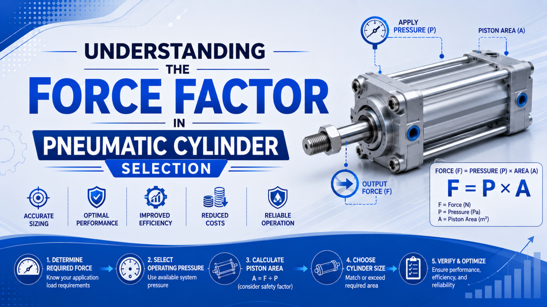
Pneumatic cylinder force factor is the effective piston area, usually expressed in square inches or square millimeters; AutomationDirect uses the term in this geometry-based sense (AutomationDirect, 2015). Multiply that area by the pressure differential across the piston to obtain theoretical force. It isn’t an efficiency ratio.
That definition fixes the first problem, but it does not finish the selection. Real machines also need a load ratio or force allowance for seal resistance, exhaust back pressure, acceleration, gravity, guide friction, pressure variation, and installation geometry. For the full equation library, use our pneumatic cylinder formula guide; this article focuses on turning the formula into a defensible bore decision.
If the job is only pressure-area-force arithmetic, use the dedicated pressure and area calculation worksheet. The scope here begins where that worksheet ends: separating force factor from load ratio, choosing the applicable selection method, and proving usable force with machine-side pressure evidence.
Key Takeaways
- Force factor is piston area.
- SMC recommends load ratio at or below 0.7 for stationary work and 0.5 for dynamic work.
- Measure both cylinder ports during the loaded part of the stroke.
- Check extension and retraction, then select bore with one documented load-ratio method instead of stacking generic percentages from unrelated applications.
The cleanest sizing worksheet keeps three terms separate: force factor describes geometry, theoretical force describes pressure acting on that geometry, and load ratio describes how much of the theoretical result the application is allowed to use. Mixing them creates false precision.
Key Takeaways
SMC’s cylinder-selection guide recommends a load ratio of 0.7 or below for stationary operation and 0.5 or below for dynamic operation. These values show why theoretical force is a ceiling, not a working-load rating (SMC Best Pneumatics, retrieved 2026-07-10).
Use this five-step sequence:
- Define the worst credible load and direction.
- Calculate extension and retraction force factors from bore and rod diameter.
- Measure or estimate both chamber pressures during the most difficult part of the moving stroke.
- Apply one documented load-ratio method.
- Select the next available bore, then verify speed, mounting, cushioning, rod stability, the full machine motion, and the lowest expected supply condition.
Do not stack every percentage found online. An explicit back-pressure subtraction, a manufacturer’s load ratio, and a separate blanket friction deduction can count the same loss twice. State what each factor includes before multiplying anything.
Citation capsule: SMC defines theoretical output as pressure multiplied by pressure-receiving area with no resistance assumed; its selection guide then applies load ratio to account for seal and bearing resistance, exhaust-pressure reaction, size, pressure, and speed. The published guide recommends 0.7 or below for stationary work and 0.5 or below for dynamic work. Those are manufacturer selection limits, not universal physical constants (SMC Best Pneumatics, retrieved 2026-07-10).
What Does Force Factor Mean in Pneumatic Cylinder Selection?
Force factor means piston area. AutomationDirect states that piston area multiplied by cylinder pressure gives available force and recommends selecting force capacity 25% above the load as a general starting rule. The term therefore belongs to geometry, while the allowance belongs to application sizing (AutomationDirect, 2015).
For a round piston:
A_piston = pi x D^2 / 4
Where:
| Symbol | Meaning | Common unit |
|---|---|---|
A_piston |
extension-side force factor | mm2 or in2 |
D |
cylinder bore | mm or in |
P |
pressure differential | MPa, bar, or psi |
F |
theoretical force | N or lbf |
On a single-rod double-acting cylinder, the retraction-side force factor is smaller:
A_retract = A_piston - A_rod
That difference is why one catalog bore can have two theoretical-force ratings. Our rod-area calculation guide covers the annulus-area math in detail.
The phrase “increase the force factor” should mean increasing effective area, normally by moving to a larger bore. Raising pressure changes force but does not change the force factor. That wording makes RFQs and review notes much harder to misread.
Force-factor evidence: A force-factor review should be reproducible from dimensions alone. Record bore, rod diameter, direction, and units, then calculate the full piston area for extension and annulus area for retraction. AutomationDirect defines force factor as piston area and states that area multiplied by cylinder pressure gives available force. ISO 15552 defines an interchangeable metric cylinder series from 32 mm to 320 mm bore, but it does not assign an application load or prove that a selected bore will move the machine. Therefore, use the standard for interface scope, the force factor for geometry, and a separate manufacturer selection method for load allowance. This separation prevents the same friction or pressure loss from being deducted more than once (AutomationDirect, 2015; ISO 15552, confirmed 2025).
How Do You Calculate Theoretical Extension and Retraction Force?
Theoretical cylinder force is pressure differential multiplied by effective area. NIST lists 1 psi as 6,894.757 Pa and 1 bar as 100,000 Pa, so a unit-controlled calculation can move cleanly between imperial and metric values (NIST pressure conversions, retrieved 2026-07-10).
For extension:
F_extend_theoretical = DeltaP x A_piston
For retraction:
F_retract_theoretical = DeltaP x (A_piston - A_rod)
In metric workshop units, 1 MPa = 1 N/mm2, so the calculation is direct. For example, at 0.5 MPa differential pressure, a 50 mm bore has a piston area of 1,963 mm2 and a theoretical extension force of about 982 N.
If that cylinder has a 20 mm rod, the retraction area is about 1,649 mm2 and the theoretical retraction force at the same 0.5 MPa differential is about 825 N. These are calculated ceilings, not recommended loads.
| Direction | Effective area | Pressure differential | Theoretical force |
|---|---|---|---|
| Extension | 1,963 mm2 | 0.5 MPa | 982 N |
| Retraction, 20 mm rod | 1,649 mm2 | 0.5 MPa | 825 N |
This article keeps the formula brief because the dedicated pressure-differential force guide explains why both chamber pressures matter.
Which Pressure Belongs in the Force Calculation?
Use the pressure differential across the piston while the cylinder is moving under the intended load. CAGI says a well-designed compressed-air system should keep compressor-to-point-of-use pressure drop within 10%, but that system guideline is not permission to assume a fixed 10% cylinder-force loss (CAGI, retrieved 2026-07-10).
For an extending single-rod cylinder, a more explicit force balance is:
F_pressure = P_cap x A_piston - P_rod x A_annulus
Both pressures must use the same reference, normally gauge pressure. The rod-side term represents exhaust back pressure acting against extension. Seal friction, guide friction, gravity, and acceleration are separate forces unless the chosen manufacturer load ratio intentionally absorbs them.
For example, a 50 mm bore with a 20 mm rod has about 1,963 mm2 cap-side area and 1,649 mm2 rod-side area. With 0.5 MPa at the cap port and 0.05 MPa at the exhausting rod port, the pressure-only extension force is about 899 N before external friction or acceleration is deducted.
Why not use the regulator setting? A gauge near the FRL may show normal pressure while a restrictive valve, undersized tube, dirty filter, or clogged muffler changes chamber pressure during motion. Our pressure-drop troubleshooting guide covers the upstream causes.
In our experience, “the pressure is normal” is rarely enough information. Cap-end and rod-end pressure during the part of the stroke where the cylinder slows or stalls separates an air-path problem from an undersized bore or mechanical bind.
Measurement capsule: CAGI’s 10% figure applies from compressor discharge to point of use across the compressed-air system. Cylinder force, however, depends on the instantaneous pressure difference across its piston. A sizing review should therefore use expected dynamic port pressure, and a commissioning check should measure both working and exhaust-side pressure during motion. Subtracting a generic 10% without measuring the machine can either hide a restriction or double-count a loss already covered by the manufacturer’s load ratio (CAGI, retrieved 2026-07-10).
How Does Load Ratio Convert Theoretical Force into a Sizing Limit?
Load ratio is the applied load divided by theoretical cylinder output. SMC recommends 0.7 or below for stationary operation, 0.5 or below for dynamic operation, and 1.0 or below for its stated guided-horizontal case. Each limit has a defined operating context (SMC Best Pneumatics, retrieved 2026-07-10).
The relationship is:
eta = applied load / theoretical output
Rearranged for selection:
allowable application load = eta_max x theoretical output
For the 50 mm bore example at 0.5 MPa:
- Theoretical extension force: 982 N.
- SMC stationary screen at
eta = 0.7: about 687 N before the remaining application checks. - SMC dynamic screen at
eta = 0.5: about 491 N; reduce the ratio further when particularly high-speed motion is required, as SMC advises.
These values are selection screens, not cylinder guarantees. Use the catalog and sizing method for the exact cylinder family being purchased.
AutomationDirect’s 25% general allowance means selected theoretical force should be at least 1.25 x load, which corresponds to a load ratio of 0.8. SMC’s dynamic guidance uses a maximum load ratio of 0.5, so theoretical output is at least twice the applied load before the remaining product checks. The values should not be averaged because they come from different selection methods and operating assumptions. Neither replaces a check of motion direction, acceleration, guide friction, chamber pressure, speed, cushioning, and the exact cylinder catalog. A purchase specification should name the method used, the pressure entered, the direction checked, and the resulting standard bore. Writing only “safety factor 1.5” leaves reviewers unable to tell whether the multiplier was applied to external load, theoretical force, measured force, or an already derated manufacturer value. That ambiguity makes later validation nearly impossible.
How Should Gravity, Acceleration, and Friction Be Added?
For constant mass, NASA states Newton’s second law as F = m x a, and gives gravitational acceleration near Earth’s surface as about 9.81 m/s2. A vertical axis must therefore include both weight and commanded acceleration before friction or process force is added (NASA Glenn, retrieved 2026-07-10).
Build the external load before choosing the cylinder:
F_required = F_process + F_gravity + F_acceleration + F_external_friction
For a vertical upward move:
F_gravity = m x g
F_acceleration = m x a
For a horizontal guided move, gravity normally loads the guide rather than opposing the cylinder directly. Guide friction, seal drag, misalignment, cable carriers, and process contact still matter, so the cylinder rod should not serve as the machine’s guide.
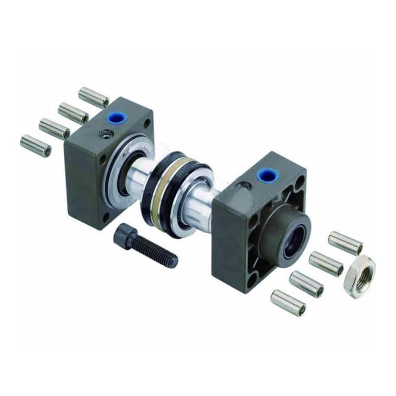
The retained image shows why friction is not one universal percentage. Seal geometry, lubrication, bore finish, pressure, temperature, contamination, and alignment all change resistance; our industrial cylinder seal guide provides component-selection context.
Force-budget evidence: NASA defines force for constant mass as
F = m x aand weight asm x g, with gravitational acceleration near 9.81 m/s2. Those terms belong in the external load budget before a bore is selected. SMC then applies load ratio to theoretical output because seal resistance, bearing resistance, exhaust-pressure reaction, size, pressure, and speed affect useful cylinder force. A transparent worksheet should identify process force, gravity, acceleration, guide friction, and measured chamber pressures, then state which remaining uncertainty is covered by the manufacturer’s selection ratio. It should not subtract a generic friction percentage and then apply a load ratio that already includes friction. Each deduction needs one physical meaning and one owner (NASA Glenn; SMC Best Pneumatics, retrieved 2026-07-10).
Avoid double-counting losses
Choose one documented method:
| Method | What you enter | What must stay separate |
|---|---|---|
| Manufacturer load ratio | theoretical output and allowed ratio | explicit loads outside the guide’s assumptions |
| Explicit force budget | two chamber pressures and named resistances | uncertainty/design allowance |
| General sizing allowance | load multiplied by a stated rule | high speed, vertical load, shock, unusual friction |
A force budget is easier to audit than a stack of percentages. Write every opposing force on its own line and mark whether the manufacturer’s load ratio already covers it; an unexplained multiplier should not control the bore choice.
Our team found that review meetings move faster when the worksheet has separate columns for calculated load, measured pressure, manufacturer allowance, and final catalog bore. That layout exposes assumptions without turning them into unsupported customer-performance statistics.
Worked Cylinder Sizing Example
For a 500 N dynamic load at 0.5 MPa, SMC’s 0.5 maximum dynamic load ratio requires at least 1,000 N theoretical output. A 50 mm bore produces about 982 N, so it misses the screen; a 63 mm bore produces about 1,559 N and passes (SMC Best Pneumatics, retrieved 2026-07-10).
Step 1: Convert the load-ratio requirement
Required theoretical force = 500 N / 0.5 = 1,000 N
Step 2: Calculate candidate force factors
At 0.5 MPa = 0.5 N/mm2:
| Candidate bore | Piston area | Theoretical extension force | Dynamic load at eta = 0.5 | Result |
|---|---|---|---|---|
| 40 mm | 1,257 mm2 | 628 N | 314 N | fail |
| 50 mm | 1,963 mm2 | 982 N | 491 N | fail |
| 63 mm | 3,117 mm2 | 1,559 N | 779 N | pass |
Step 3: Check what the screen does not prove
The 63 mm result is only the force gate. Next, confirm the actual bore series, retract force, stroke, rod buckling, mounting, side load, target speed, valve flow, tubing, cushioning, air quality, and available pressure during motion. ISO 15552 covers detachable-mount cylinder dimensions from 32 mm to 320 mm and up to 10 bar, but it does not validate the application (ISO 15552, confirmed 2025).
Worked-example capsule: A 500 N dynamic load with SMC’s 0.5 load-ratio limit needs 1,000 N of theoretical output. At 0.5 MPa, the calculated extension forces are 628 N for 40 mm bore, 982 N for 50 mm, and 1,559 N for 63 mm; the 63 mm candidate passes the force screen, but the final selection still needs speed, mounting, cushioning, rod, and dynamic-pressure checks (SMC Best Pneumatics, retrieved 2026-07-10).
How Do You Verify the Selected Cylinder on the Machine?
AutomationDirect recommends at least 25% more calculated force than the actual requirement as a general starting point, but machine verification must confirm that the selected cylinder reaches the load at the intended speed without binding or excessive impact (AutomationDirect cylinder sizing, retrieved 2026-07-10).
Use this commissioning sequence:
- Match the part number and approved drawing.
- Isolate every hazardous-energy source before mechanical inspection, alignment work, or adjustment.
- Inspect the external guide, mounting datums, rod connection, tubing, sensors, and full clearance envelope.
- Jog slowly.
- Measure cap-end and rod-end pressure during the highest-load portion of extension and retraction, not only while the machine is idle.
- Record cycle time, process load, regulator setting, port pressures, flow-control positions, and cushioning settings as the accepted baseline.
- Repeat at the lowest expected plant pressure and highest credible process load.
- Stop the trial if binding, hard impact, leakage, unstable speed, abnormal sound, or mount movement appears; correct the cause before increasing speed.
If force is adequate but speed is not, treat that as a flow problem. Use the pneumatic flow-rate guide before increasing bore or plant pressure. If the cylinder hits the end cap hard, review end-of-stroke cushioning rather than using extra force to mask the impact.
Verification capsule: A cylinder selection passes only when the machine reproduces the intended load, pressure, speed, and end-of-stroke behavior; measure both cylinder-port pressures during motion because an upstream regulator reading cannot reveal exhaust back pressure or a local restriction. Record the accepted conditions as a maintenance baseline, including load, cycle time, pressure at the difficult part of the stroke, flow-control position, and cushioning setting. Then repeat the check at the lowest expected supply pressure and highest credible process load. If the cylinder later slows, the baseline separates lost pressure, exhaust restriction, added friction, load change, leakage, and control adjustment before parts are replaced. CAGI’s system-level pressure-drop guidance provides context, but the two chamber measurements provide the cylinder force evidence (CAGI, retrieved 2026-07-10).
From our work, a commissioning record is more valuable when it contains numbers and settings instead of only “passed.” Maintenance can compare the current machine with the accepted state before replacing the actuator.
Editorial ownership and engineering context are described on the About page. For application-specific drawings, loads, or pressure measurements that cannot be resolved from the article, use the contact page and include the machine’s operating data.
FAQs About Pneumatic Cylinder Force Factor
ISO 15552 covers a 32-320 mm bore range for its detachable-mount, 10 bar metric series, but force-factor selection still depends on effective area, direction, dynamic pressure, and application load ratio. These five answers address the decisions most likely to change bore selection (ISO 15552, confirmed 2025).
Is pneumatic cylinder force factor the same as a safety factor?
No. Force factor is piston area, according to AutomationDirect. A safety factor, force allowance, or load ratio is a separate selection rule applied to the load or theoretical output. Keep both terms visible in the worksheet so area, pressure, and design reserve cannot be mistaken for one number.
Should I always add 25% to the required cylinder force?
AutomationDirect presents 25% extra calculated force as a general starting rule. It is not universal. SMC recommends a 0.5 maximum load ratio for dynamic operation, which provides more reserve. Use the method for the selected product and operating case, then verify pressure and motion on the machine.
Why is pneumatic cylinder retraction force lower than extension force?
The rod occupies part of the pressure-receiving area on retraction. For a 50 mm bore with a 20 mm rod, the calculated area falls from about 1,963 mm2 to 1,649 mm2. At the same 0.5 MPa differential, theoretical force falls from about 982 N to 825 N.
Can I use regulator pressure in the force calculation?
Use it only for an early estimate. Final review should use expected pressure differential at the cylinder during motion. CAGI allows up to 10% compressor-to-point-of-use drop in a well-designed system, while the valve, tubing, fittings, flow controls, and exhaust path can create additional local behavior.
Does a larger bore always solve a weak-cylinder problem?
No. A larger bore increases force factor, but it also increases chamber volume and required airflow. If the real cause is a restricted valve, long tube, clogged muffler, side load, or low dynamic pressure, the larger cylinder may remain slow and consume more air without fixing the machine interface.
Sources and Retrieval Notes
The 7 primary or first-party sources below support the definitions, formulas, selection limits, and worked example, beginning with AutomationDirect’s force-factor definition. The original incorrect ISO URL and unsupported percentage tables were not retained. All web sources were retrieved on 2026-07-10 unless another confirmation date is stated.
- AutomationDirect: Pneumatic Cylinder Design Factors, force factor as piston area and a 25% general force allowance. Published 2015; retrieved 2026-07-10.
- AutomationDirect: Cylinder Sizing and Force, piston-area equations, rod-area effect, 25% starting allowance, and differential-pressure caution. Retrieved 2026-07-10.
- SMC Best Pneumatics: Bore Size Selection, theoretical output, seal and bearing resistance, exhaust-pressure reaction, and load-ratio guidance. Retrieved 2026-07-10.
- CAGI: Working With Compressed Air, compressor-to-point-of-use pressure-drop guidance. Retrieved 2026-07-10.
- NIST: Pressure and Gas Flow Unit Conversions, pressure conversion values. Retrieved 2026-07-10.
- NASA Glenn: Weight and Mass,
F = m x a,W = m x g, and 9.81 m/s2 gravitational acceleration. Retrieved 2026-07-10. - ISO 15552:2018, detachable-mount cylinder dimensions, 10 bar series, and 32-320 mm bore scope. Confirmed current in 2025; retrieved 2026-07-10.