

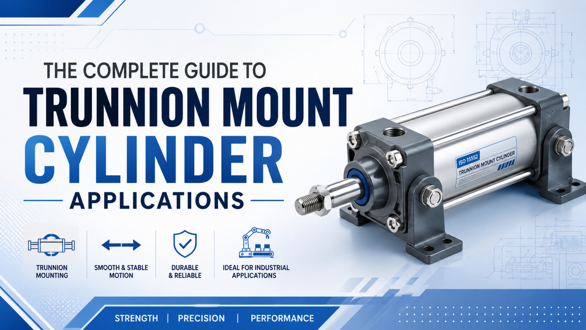
A trunnion mount cylinder is a pivot-mounted cylinder for mechanisms where the piston rod follows a curved path in one plane. The trunnion doesn’t give a cylinder unlimited rotation or immunity to misalignment. It creates a defined pivot axis, and the machine designer must support that axis without bending the trunnion pins.
Parker identifies three common arrangements: head trunnion, cap trunnion, and intermediate fixed trunnion. Its pneumatic actuator catalog also gives a useful long-stroke screening rule for head-trunnion applications: when stroke exceeds 5 times bore and piston speed exceeds 35 ft/min, consult the manufacturer (Parker 0900P, page A10).
Key Takeaways
- A trunnion guides pivoting in one plane, not arbitrary multi-axis motion.
- The pins should carry shear; rigid blocks minimize bending stress.
- Head, cap, and intermediate positions create different rod and bearing loads.
- Parker lists a 0.707 effective-thrust factor at 45° (source).
- Quote requests need geometry, pressure, speed, load, environment, and test criteria.
Technical basis: the mounting and force rules below come from manufacturer engineering data. Author and company information is available on the Jack Chen author page and About Us page.
Table of Contents
- What Does a Trunnion Mount Cylinder Actually Do?
- Which Trunnion Position Fits the Load Path?
- How Should the Trunnion Pins and Bearing Blocks Be Supported?
- How Does Cylinder Angle Change Effective Thrust?
- What Clearances, Rod Loads, and Speed Limits Must Be Checked?
- When Is a Trunnion Mount the Wrong Choice?
- Trunnion Mount Cylinder RFQ Checklist
- Installation and Commissioning Checklist
- FAQs About Trunnion Mount Cylinder Applications
What Does a Trunnion Mount Cylinder Actually Do?
A trunnion mount gives the cylinder body a fixed transverse pivot axis so the actuator can swing as the driven mechanism moves through an arc. Parker limits this description to a curved rod path in 1 plane (Parker 0900P, page A10). It doesn’t automatically compensate for every type of misalignment.
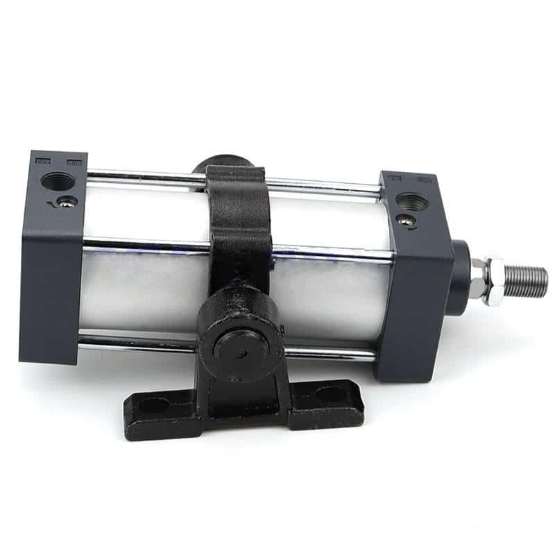
Trunnion mount cylinder is a pneumatic or hydraulic cylinder with two coaxial pins, or equivalent trunnion hardware, perpendicular to the cylinder centerline. Those pins sit in bearing blocks attached to the machine frame. A rod clevis or rod eye normally provides the matching pivot at the moving end.
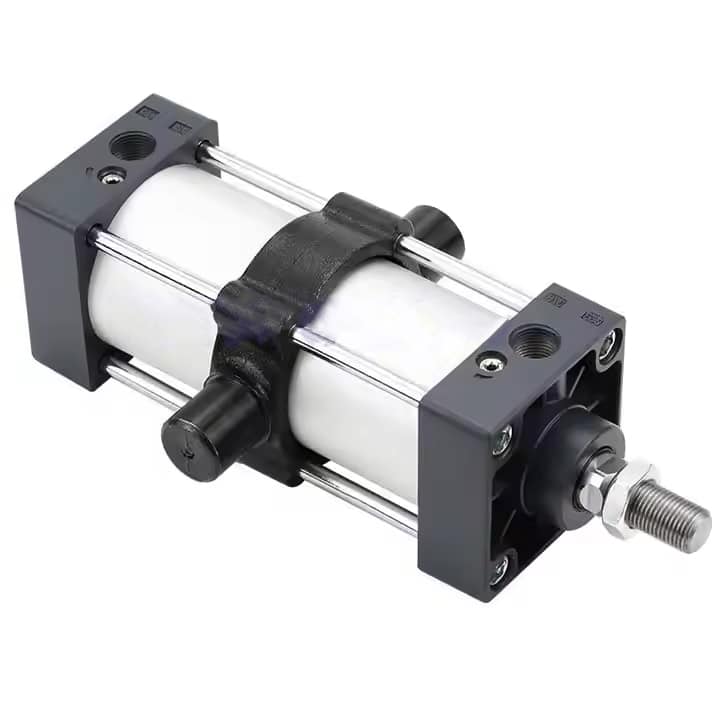
The mount changes the cylinder’s relationship to the frame, not the basic force produced by pressure on piston area. The cylinder still extends and retracts along its own centerline. What changes is the angle between that centerline and the driven lever or linkage.
Good application signals
Consider a trunnion arrangement when all four statements are true:
- The load connection travels through a predictable arc.
- The cylinder only needs to pivot about one defined axis.
- The machine can provide rigid, aligned support on both trunnion pins.
- A pivoting rod-end connection can keep the linkage free throughout the stroke.
Typical mechanisms include bin tippers, hinged chutes, tilting tables, damper linkages, lid actuators, and lever-operated clamps. These examples do not prove that a trunnion is correct. The full working arc, thrust direction, rod stability, end-of-stroke energy, and surrounding clearance still need to be checked.
What the mount does not do
A trunnion is not a linear guide. It should not be selected as a way to make the piston rod carry an overhung load. It also is not a universal joint. If the driven member can move out of the intended pivot plane, a spherical bearing, guided load, redesigned linkage, or different actuator architecture may be required.
For the underlying pressure and piston-area calculation, use the force from pressure and area guide. The trunnion analysis begins after the available cylinder thrust is known.
Which Trunnion Position Fits the Load Path?
Head, cap, and intermediate trunnions can all permit the same basic pivoting motion, but they do not load the cylinder and frame in the same way. Parker identifies these 3 positions and favors the intermediate fixed arrangement for balancing cylinder weight or fitting the machine geometry (Parker 0900P, page A10).
| Trunnion position | Pivot location | Useful design reason | Main item to verify |
|---|---|---|---|
| Head trunnion | Near the rod end | Can reduce the piston-rod diameter required for some pivot applications | Overhanging cap-end mass, bearing load, long-stroke speed |
| Cap trunnion | Near the rear cap | Similar kinematics to a cap clevis while supporting both sides of the cylinder | Rod column load, swing clearance, hose motion |
| Intermediate fixed trunnion | Specified point along the body | Can balance the cylinder or place the pivot where the linkage requires it | Exact XI dimension and access to both support blocks |
XI dimension is the specified axial distance used to locate an intermediate trunnion on the cylinder body. The exact reference points vary by manufacturer drawing, so an RFQ should state the dimension using the supplier’s drawing convention. Parker notes that this position is fixed at manufacture and is not easily changed later.
A practical position-selection sequence
Start with the driven pivot and draw the rod-end pin path at fully retracted, mid-stroke, and fully extended positions. Then locate a cylinder-body pivot that keeps the required stroke, force angle, clearances, and rod loading acceptable at every position.
For an intermediate trunnion, estimate the cylinder center of gravity with the relevant rod position and installed fittings. Moving the trunnion toward that balance point can reduce the gravitational moment acting on the trunnion bearings, but it may change the rod column length and the space required behind the pivot.
A three-position geometry review can show why the best trunnion position is rarely found from the retracted machine alone. The critical condition may occur near mid-stroke, where effective lever angle falls, or at extension, where the exposed rod and moving cylinder mass create the least favorable combination.
Use the pneumatic cylinder rod buckling calculator when the rod works in compression. It is a screening tool, not a replacement for the manufacturer’s piston-rod selection chart.
How Should the Trunnion Pins and Bearing Blocks Be Supported?
Parker states that trunnion pins are intended for shear loads and should not carry bending stress. It recommends rigid pillow blocks with bearing length at least equal to 100% of pin length, positioned close to the trunnion shoulder faces (Parker 0900P, page A10). That support geometry isn’t optional.
Four support rules
- Use both sides. Support both trunnion pins rather than cantilevering one pin unless a manufacturer-approved mounting kit is designed for that condition.
- Keep bearings close. A large gap from bearing to shoulder increases the bending arm on the pin.
- Align before tightening. The two bearing bores must share one axis. Do not pull a misaligned block into position with its fasteners.
- Match the rod-end axis. Parker’s installation guidance calls for the rod-end pivot pin to be in line with and parallel to the trunnion-pin axis.
The support material, bearing clearance, lubrication method, and allowable bearing pressure should come from the selected cylinder and bracket data. For example, Festo’s current LNZG-40/50 trunnion support lists a 2.5 kN maximum load capacity, showing why the accessory rating must be checked rather than inferred from cylinder bore alone (Festo LNZG-40/50).
Avoid false self-alignment
Do not expect loose pillow blocks to cure a bad frame. Loose clearance can add impact, fretting, and positional play. Some Parker cylinder guidance specifically warns against self-aligning supports on trunnions because they can allow bending forces to develop. If the mechanism truly needs angular freedom in more than one plane, redesign the joint deliberately.
How Does Cylinder Angle Change Effective Thrust?
Cylinder thrust and useful turning thrust are not the same when a cylinder drives a lever at an angle. Parker defines the power factor as sin A and lists 0.707 at 45°, where A is the acute angle between the cylinder centerline and lever axis (Parker 0900P, page A10).
Effective thrust is the component of cylinder thrust acting perpendicular to the lever arm. It is the component that creates turning moment.
T = F × sin(A)
Where:
- T is effective thrust perpendicular to the lever arm.
- F is cylinder thrust along the cylinder centerline.
- A is the acute angle between the cylinder centerline and lever axis.
| Angle A | Parker power factor, sin A | Effective thrust from a 2,000 N cylinder |
|---|---|---|
| 15° | 0.259 | 518 N |
| 30° | 0.500 | 1,000 N |
| 45° | 0.707 | 1,414 N |
| 60° | 0.867 | 1,734 N |
| 75° | 0.966 | 1,932 N |
| 90° | 1.000 | 2,000 N |
Parker’s 45° entry is a 0.707 force factor. It is not evidence that every trunnion cylinder has a standard +/-45° travel limit. Permitted swing is set by the machine geometry, ports, hoses, rod-end joint, support blocks, sensor hardware, and the selected cylinder’s drawings.
A mechanism can have adequate force at both end positions and still stall near the middle if the cylinder-to-lever angle becomes unfavorable there. Calculate the force factor at several positions through the stroke, then size against the worst required torque point rather than the most convenient drawing position.
For a worked review of bore, pressure, and piston area, see the pneumatic cylinder force calculation guide. Remember that pressure measured at the regulator while the machine is idle may be higher than pressure at the cylinder during motion.
What Clearances, Rod Loads, and Speed Limits Must Be Checked?
A working trunnion installation needs clearance for the entire moving envelope, stable rod loading, controlled speed, and suitable end cushioning. Parker’s 5-times-bore and 35 ft/min figures apply to a specific head-trunnion catalog check, so use them as an escalation trigger rather than a universal design limit (Parker 0900P, page A10).
Swing-envelope clearance
Model the cylinder barrel, end caps, ports, fittings, tubes, sensors, cable connectors, rod-end accessory, and fasteners at several positions. Flexible tubing needs a controlled bend radius and strain relief. It must not become the mechanical stop or pull across a sharp frame edge.
Check maintenance access too. A design that clears during motion may still trap the trunnion block fasteners, cushioning screws, sensor connectors, or rod-end pin after the surrounding machine is assembled.
Rod column and side-load review
The rod should transmit axial force. It should not guide the load or correct a skewed lever. Compression applications need a buckling check based on rod diameter, unsupported length, end condition, material, and peak compressive load. Long strokes deserve particular attention because the rod’s slenderness rises rapidly with length.
The high-speed pneumatic cylinder checklist covers flow, cushioning, moving mass, and validation details. For a trunnion layout, add pivot-bearing velocity and cylinder-body overhang to that review.
Speed and end-of-stroke energy
Trunnion bearings see repeated oscillation as the cylinder cycles. Higher piston speed can increase reversal shock, fitting motion, and end-of-stroke energy even if the static thrust calculation is unchanged. State the required stroke time, cycles per minute, moving mass, center-of-gravity offset, and duty pattern in the RFQ.
Don’t use a generic annual, semiannual, or quarterly lubrication interval without product documentation. Inspection and lubrication frequency should follow the cylinder, trunnion support, bearing, environment, cycle count, and machine risk assessment.
| Check | Input needed | Failure mode if missed | Verification method |
|---|---|---|---|
| Full swing envelope | CAD geometry at multiple positions | Collision, tube damage, blocked service access | CAD interference check plus slow manual cycle |
| Rod compression | Peak force, rod diameter, unsupported length, end condition | Buckling or permanent bend | Manufacturer chart and rod buckling calculation |
| Bearing load | Cylinder mass, thrust reaction, overhang, dynamic load | Pin or bearing wear, frame cracking | Supplier rating plus structural review |
| End energy | Moving mass, speed, cushion type, stroke | Impact, bounce, noise, seal damage | Cushion calculation and production-speed test |
| Air delivery | Dynamic pressure, valve flow, tube ID and length | Slow stroke or force loss | Gauge at cylinder port during motion |
When Is a Trunnion Mount the Wrong Choice?
A trunnion mount is the wrong choice when the load needs rigid linear guidance, continuous rotation, or motion in more than 1 pivot plane. Parker defines a trunnion application around a curved rod path in 1 plane, which excludes multi-axis movement without another engineered joint (Parker 0900P, page A10).
| Application need | Better first option | Why |
|---|---|---|
| Straight guided transfer with long stroke | Guided or rodless cylinder | The carriage or external guide manages load moments |
| Pivot at one cylinder end | Cap clevis or spherical bearing mount | Simpler end-pivot geometry may fit the linkage |
| Rotation through repeated full revolutions | Pneumatic rotary actuator or motor | Avoids twisting hoses around an oscillating linear cylinder |
| High transverse or overhung load | External linear guide plus cylinder | Separates guidance from thrust production |
| Rigid coaxial push or clamp | Flange, foot, or tie-rod mount | No body pivot is required when alignment stays fixed |
| Motion in multiple angular planes | Engineered spherical joint arrangement | A basic trunnion only pivots about one axis |
A rodless cylinder is not a direct trunnion substitute, but it can be a better architecture when the real constraint is long travel in limited length. The rodless cylinder mounting guide explains how alignment and external guidance differ in that layout.
For replacement work, do not match only bore and stroke. Compare mounting standard, pivot-center dimensions, retracted length, rod thread, port position, cushion type, sensor interface, and allowable loads. The ISO 6432 replacement guide shows the drawing-overlay method even though the specific standard and mounting dimensions differ.
Trunnion Mount Cylinder RFQ Checklist
A quote can only be evaluated when suppliers are solving the same motion problem. Parker distinguishes 3 trunnion positions and publishes 18 angle factors from 5° to 90°, so the RFQ must define geometry, pressure, dynamic load, environment, and acceptance tests (Parker 0900P, page A10).
Cylinder and motion data
- Cylinder standard or existing manufacturer and full part number
- Bore, stroke, rod diameter, rod thread, and action type
- Head, cap, or intermediate trunnion requirement
- XI dimension and its drawing reference points for an intermediate trunnion
- Retracted, mid-stroke, and extended linkage drawings
- Required stroke time, cycles per minute, and daily operating pattern
- Cushion type and allowable end-stop impact
Force and load data
- Minimum dynamic pressure measured at the cylinder port
- Push or pull direction at each critical mechanism position
- Required output force or torque through the full arc
- Cylinder-to-lever angle at critical positions
- Moving mass, center of gravity, and external load offset
- Any compressive rod condition and unsupported rod length
- Shock, vibration, emergency-stop, and gravity-drop conditions
Installation and environment data
- Bearing-block drawings, material, lubrication method, and support spacing
- Rod-end pivot type and pin-axis orientation
- Available swing envelope, fitting space, and service access
- Ambient temperature, dust, washdown, corrosion, and chemical exposure
- Port thread, tube size, valve flow, sensor type, voltage, and connector
- Applicable machine safety requirements and requested documentation
Add one marked-up side-view drawing with three cylinder positions to the RFQ. That single drawing often exposes missing angle data, a trapped fitting, a reversed XI reference, or a rod-end pivot that cannot remain parallel to the trunnion axis.
The custom cylinder lifecycle guide provides a broader path from requirements through first-article approval. For a trunnion cylinder, freeze the XI dimension and pivot-center datums in the approved drawing before production.
Installation and Commissioning Checklist
Commissioning should prove free pivoting, structural alignment, air-circuit performance, and safe behavior before production speed is enabled. Isolate hazardous energy before hands enter the mechanism. In the United States, OSHA 29 CFR 1910.147 defines requirements for controlling hazardous energy during servicing and maintenance (OSHA).
- Verify the received cylinder, trunnion position, rod-end accessory, pins, and support blocks against the approved drawing.
- Confirm the frame mounting faces are flat, rigid, and free of weld distortion or burrs.
- Align both trunnion bearing bores on one axis before final tightening.
- Place support bearings close to the trunnion shoulders as the design allows.
- Confirm the rod-end pivot axis is parallel to the trunnion axis.
- With energy isolated, move the mechanism through its full arc and check for binding or interference.
- Inspect tubes, fittings, sensors, and cables at retracted, mid-stroke, and extended positions.
- Pressurize at a reduced, controlled setting and check for leakage and unexpected motion.
- Measure pressure at the cylinder during motion, not only at the upstream regulator.
- Increase speed and load in controlled steps while observing cushion behavior, vibration, pin movement, and frame deflection.
- Record the accepted regulator setting, flow-control settings, stroke time, pressure, load, and inspection points.
- Reinspect fasteners, bearing blocks, rod-end pins, tubes, and witness marks after the initial production run.
Do not force a stiff mechanism by raising pressure. Isolate the machine and find the source of binding. Common causes are non-coaxial bearing blocks, non-parallel pivot pins, a rod-end joint at its articulation limit, frame deflection, a trapped tube, or interference that only appears at one point in the arc.
Base maintenance on observed condition within the manufacturer’s instructions. Trend changes in pin play, noise, stroke time, leakage, pressure during motion, lubricant condition, and fastener witness marks. A rising rate of change is more useful than a made-up universal interval.
FAQs About Trunnion Mount Cylinder Applications
These 5 answers address the selection errors most likely to affect trunnion mount cylinder applications. Parker’s table covers 18 angles from 5° to 90° and identifies 3 trunnion positions, but product-specific drawings and ratings still govern the final design (Parker 0900P, page A10).
What is a trunnion mount cylinder used for?
A trunnion mount cylinder is used when the cylinder body must pivot as its rod end follows a curved path in one plane. Common mechanisms include tilting chutes, hinged covers, lever clamps, and dumpers. Use it only when the frame can support both trunnion pins without bending them.
Can a trunnion mount cylinder rotate 360 degrees?
Don’t assume it can. Designers normally use a basic trunnion cylinder for limited oscillating motion through the machine’s working arc. Ports, tubes, sensors, rod-end joints, and surrounding structure restrict movement. Continuous rotation usually requires a rotary actuator, motor, rotary union, or another purpose-designed architecture.
Is 45 degrees the standard angular limit for every trunnion cylinder?
No. Parker’s table lists 0.707 as the effective thrust factor at 45 degrees because sin 45° equals 0.707. That table calculates useful lever thrust; it does not establish a universal ±45° travel range. Check the selected cylinder drawing and the complete machine swing envelope.
How should trunnion pins be supported?
Parker recommends rigid bearing blocks with bearing length at least as long as the trunnion pins and support close to the trunnion shoulder faces. The pins are intended for shear, not bending. Both bearing bores should be coaxial, and the rod-end pivot pin should remain parallel to the trunnion axis.
What information is required to size a trunnion mount cylinder?
Provide bore and stroke targets, dynamic pressure, force or torque through the full arc, linkage angles, speed, cycle rate, moving mass, center of gravity, rod loading, trunnion position, XI dimension, support-block geometry, environment, cushioning, sensor details, and acceptance tests. A three-position drawing is strongly recommended.
The engineering decision is straightforward: choose a trunnion mount because the linkage requires a defined one-plane pivot, then prove the pin support, force angle, rod stability, dynamic behavior, and clearances. Don’t choose it as a general cure for misalignment. For an application review, send the marked-up mechanism drawing and RFQ data through the Contact Us page.
Source and video qualification details
Primary engineering sources
- Parker Pneumatic Actuator Products, Catalog 0900P, page A10. Evidence role: trunnion types, pin support, long-stroke screening rule, XI dimension, rod-end pin alignment, and angle power factors. Source type: manufacturer engineering catalog.
- Parker Pneumatic Tie Rod Style Cylinders, Series U250/U250N. Evidence role: bearing-block alignment, rigid support, lubrication, and parallel rod-end pivot axis. Source type: manufacturer installation and maintenance catalog.
- Festo: The significance of ISO standards in pneumatics. Evidence role: ISO 15552 cylinder and mounting-option context. Source type: manufacturer technical article.
- Festo LNZG-40/50 trunnion support. Evidence role: example accessory rating and ISO 15552 context. Source type: current manufacturer product data.
- OSHA 29 CFR 1910.147. Evidence role: hazardous-energy control during servicing and maintenance. Source type: government regulation.
Video qualification checked 2026-07-10
- How to Choose Pneumatic cylinder - Choosing the Right Pneumatic Cylinder? Start HERE!, BREADBOARD DIY FACTORY. Published 2025-05-13; duration 5:15; 5,477 views; channel 2.85K subscribers; captions available; qualification score 57.6/100. Selected for cylinder-selection relevance, recency, minimum duration, channel size, view threshold, and an estimated 98.7% like ratio.
- Pneumatic Cylinder Force Calculation । Effect of Friction & Cushioning on Cylinder Force., Industrial Solutions. Published 2024-06-27; duration 7:01; 5,989 views; channel 87.9K subscribers; captions available; qualification score 52.7/100. Selected for force-calculation relevance, minimum duration, channel authority, view threshold, and an estimated 98.1% like ratio.
YouTube does not expose public dislike counts. The ratio screen used Return YouTube Dislike community estimates checked on 2026-07-10, so the ratios are qualification metadata rather than performance claims.