

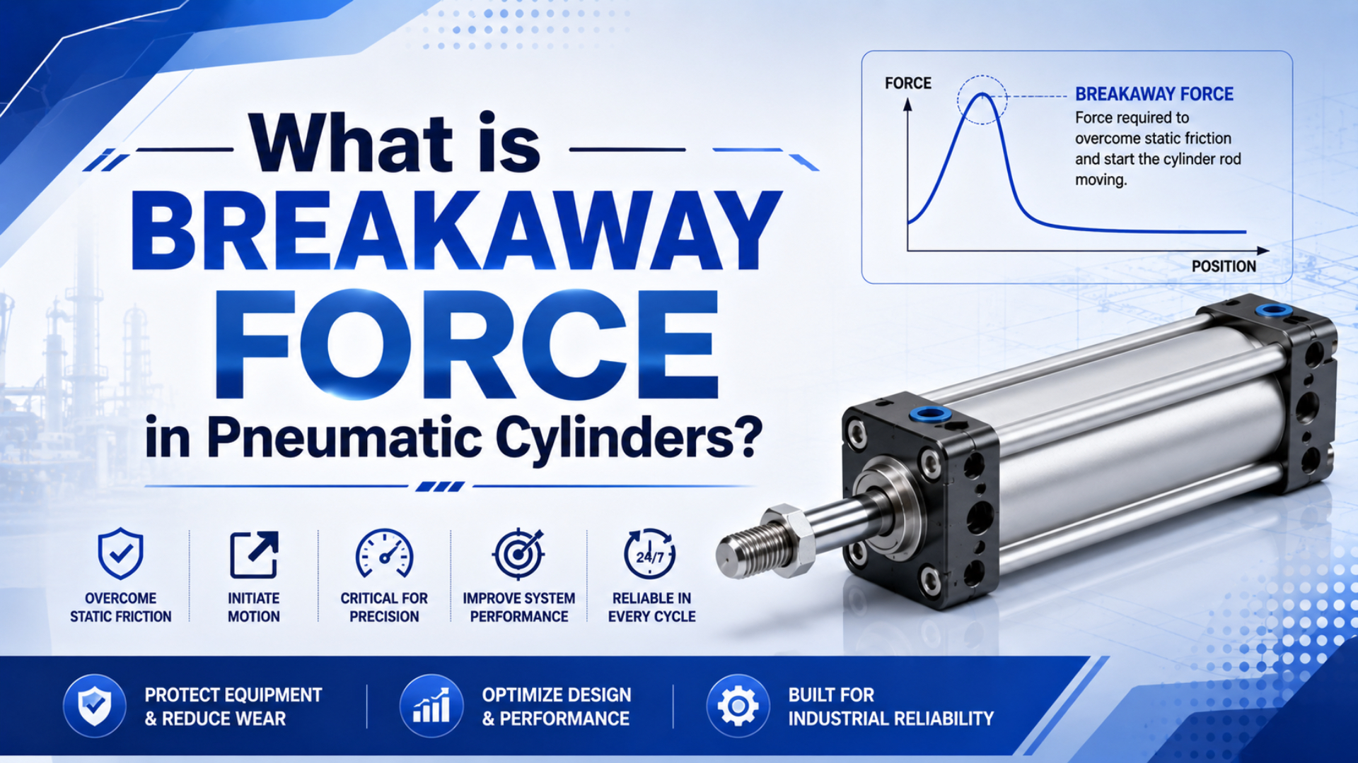
Breakaway force in pneumatic cylinders is the net force needed to start the piston and attached load moving from rest. The unit matters. It must overcome seal friction, guide friction, gravity or process load, spring force, mechanical binding, and pressure trapped on the opposite side. It is a force, measured in newtons or pounds-force, not energy.
There is no defensible rule that every cylinder needs 25-50% more force to start. SMC publishes model-specific minimum operating pressures and says sliding resistance changes with pressure (SMC Basic Characteristics of Air Cylinders, retrieved 2026-07-10). Calculate the load path, then measure both cylinder ports at the first detectable motion.
There is no primary evidence for one universal 25-50% breakaway multiplier. Use product data, a transparent worksheet, and a defined field test instead of copying a generic percentage into the cylinder force margin.
Breakaway pressure is the active-chamber pressure at which motion begins under a defined test condition. Running force is the force available after motion starts. Stick-slip is repeated stopping and releasing during motion, not simply one high starting-pressure reading.
Key Takeaways
- SMC lists minimum operating pressures from 0.005 to 0.03 MPa across representative smooth-cylinder models, proving that starting behavior is product-specific.
- Calculate pressure force on both piston faces, then subtract the load, spring, seal, guide, and binding resistance.
- Measure port pressure at first motion after a defined dwell; do not rely on the upstream regulator gauge.
The phrase “breakaway force” has two meanings in pneumatic catalogs. For a conventional rod cylinder, it usually describes the resistance that must be overcome to start sliding. For a magnetically coupled rodless cylinder, it may describe the coupling force at which the external carriage separates from the internal piston. SMC’s representative smooth-cylinder models span 0.005-0.03 MPa minimum operating pressure, while Festo’s DGO data uses breakaway force as a magnetic-coupling value (SMC; Festo DGO, retrieved 2026-07-10). The first is a starting-pressure characteristic; the second limits transferable carriage force. Before using either number, identify the component and failure mode that the catalog is rating. Never substitute one rating for the other. Write the term and unit beside every procurement value.
Short Answer: Breakaway Force Starts Motion
SMC’s current smooth-cylinder catalog lists minimum operating pressures between 0.005 and 0.03 MPa for representative models and bore groups (SMC Smooth Cylinder Catalog, retrieved 2026-07-10). That sixfold range is why breakaway force should come from model data or a controlled measurement, not one universal percentage.
At rest, pressure builds in the commanded chamber while the opposite chamber may retain back pressure. Motion starts only when the resulting pressure-force difference exceeds all resistance in the load path. The threshold can change with direction because a single-rod cylinder has different effective areas on its cap and rod sides.
Use this force balance for extension:
Net starting force =
  cap-end pressure x full piston area
  - rod-end pressure x annular area
  - external load resistance
  - spring force
  - seal and guide friction
  - mechanical binding
A positive result is only a calculated margin. It is not a guarantee. The selected cylinder still needs model-specific pressure, speed, side-load, mounting, temperature, and cushioning checks. If the machine is already built, a pressure trace and first-motion signal usually tell you more than another catalog estimate.
What Does Breakaway Force Mean in a Pneumatic Cylinder?
ISO 6431:1992 was withdrawn in 2004, while the current 18-page ISO 15552:2018 standard covers detachable-mounting cylinders from 32 to 320 mm bore at up to 1,000 kPa, or 10 bar (ISO 6431; ISO 15552, confirmed 2025). Neither standard supplies one universal breakaway-force ratio.

SI Series profile pneumatic cylinder
The legacy SI product name refers to ISO 6431 geometry, but new engineering documentation should recognize ISO 15552 as the replacement standard. Interchangeable mounting dimensions do not guarantee identical seal friction, minimum operating pressure, allowable side load, cushioning, or low-speed behavior.
Breakaway force includes whatever resists the first movement:
- piston-seal and rod-seal friction
- bearing, wear-ring, and external-guide friction
- the component of gravity along the motion axis
- process load, return spring, hose drag, and cable drag
- back pressure in the exhausting chamber
- misalignment, side load, tight clevises, and mechanical binding
Do not confuse these resistances with magnetic coupling capacity. A magnetic rodless cylinder can have enough pneumatic thrust to move its internal piston but still decouple its carriage. The magnetic rodless cylinder guide treats that separate coupling limit.
How Is Starting Force Different From Running Force?
SMC states that its smooth-cylinder range can operate stably at 5 mm/s, while Parker explains that longer stationary periods can raise breakaway friction as lubricant is displaced and the seal conforms to the surface (SMC Smooth Cylinders; Parker Sealing Products, retrieved 2026-07-10).
Starting force is a threshold. Running force is a moving-state balance after the piston has displaced, the lubricant film has changed, and the valve is filling and exhausting the chambers. The difference is not a fixed percentage, and it may vary from one direction to the other.
The most useful comparison is condition-based:
| Test | Reveals | Avoid assuming |
|---|---|---|
| After dwell | Seal/lubricant state | One cycle covers every dwell |
| Warm cycles | Running friction | Warm predicts overnight restart |
| Loaded/unloaded | External resistance | Every change is seal friction |
| Extend/retract | Area and exhaust differences | Both directions match |
The practical specification is not “breakaway force must be 30% above running force.” It is a test envelope: direction, dwell time, temperature, load, supply condition, valve state, speed setting, and the pressure at both ports when displacement first appears. SMC’s 0.005-0.03 MPa catalog span and Parker’s dwell guidance show why the result belongs to a product and condition, not a universal percentage (SMC; Parker, retrieved 2026-07-10). Record the command, active-port pressure, opposing-port pressure, and first detectable displacement on one time base. A warm repeated cycle cannot represent an overnight start unless the two conditions have been shown to agree. Without this context, two breakaway readings are not comparable. That is the minimum record needed for a valid comparison.
How Do You Calculate Net Starting Force and Breakaway Pressure?
For example, a transparent 63 mm bore and 20 mm rod worksheet has a 3,117 mm2 piston area and 2,803 mm2 rod-side annular area. Those dimensions fall inside ISO 15552’s 32-320 mm bore series (ISO 15552, confirmed 2025). These inputs are assumptions, not a product rating.
The companion pressure-differential force guide covers the general net-force equation during cylinder motion. This section uses that balance only at first movement and solves for the active-chamber pressure that makes the starting margin reach zero.
NIST defines the pascal as one newton per square meter, so 1 MPa is equivalent to 1 N/mm2 (NIST Guide to the SI, retrieved 2026-07-10). That conversion keeps the worksheet compact without mixing pressure and force units.
Assume extension with these conditions:
- cap-end pressure: 0.25 MPa
- rod-end back pressure: 0.05 MPa
- external resisting load: 400 N
- combined seal and guide resistance: 90 N
- no return spring
The force balance is:
Cap-end pressure force = 0.25 N/mm2 x 3,117 mm2 = 779 N
Rod-end opposing force = 0.05 N/mm2 x 2,803 mm2 = 140 N
Net starting margin = 779 - 140 - 400 - 90 = 149 N
The estimated threshold cap-end pressure is:
Required cap-end pressure =
  (rod-end opposing force + external resistance + seal/guide resistance)
  / full piston area

= (140 N + 400 N + 90 N) / 3,117 mm2
= 0.202 MPaThis equation is better than multiplying the load by a generic static-friction coefficient because it keeps the pneumatic and mechanical terms dimensionally correct. In the worked example, 0.202 MPa produces about 630 N on the 3,117 mm2 piston area, balancing 140 N of rod-side pressure force, 400 N of external resistance, and 90 N of assumed seal and guide friction. NIST defines pressure in newtons per square meter, which supports the equivalent MPa and N/mm2 calculation (NIST, retrieved 2026-07-10). The 90 N term remains an assumption. Replace it with manufacturer data or a measured value when low speed, long dwell, or a small starting margin matters. Changing back pressure or external resistance moves the threshold immediately. Document every assumption with the result.
How Can You Measure Breakaway Pressure on the Machine?
CAGI says a well-designed air system should keep compressor-to-point-of-use pressure drop within 10%, so a regulator gauge cannot prove what reaches the cylinder during a start command (CAGI Pressure Drop FAQs, retrieved 2026-07-10). Measure the active and opposing ports as close to the cylinder as the approved test setup allows.
Use a controlled test sequence:
- Define direction, payload, fixture state, temperature, dwell time, regulator setting, and speed-control position.
- Install suitable pressure transducers on both cylinder ports without creating unsafe tubing or trapped-energy conditions.
- Record command state, both pressures, and displacement or position-sensor change on the same time base.
- Start from the defined dwell condition and identify the first repeatable motion above sensor noise.
- Record active-port pressure, opposite-port pressure, and the calculated net pressure force at that instant.
- Repeat enough trials to see normal spread, then compare extension, retraction, cold start, warm cycling, and load states.
What should count as motion? Define it before testing. Capture the start, not the end. For example, a reed switch at the end of stroke is too late. Use an encoder, displacement sensor, suitable machine position signal, or another method with enough resolution to identify the onset of movement.
Do not loosen a fitting to see whether air is present. Isolate stored energy according to the machine procedure, use rated test points and instruments, and restore the circuit before production. The broader pneumatic troubleshooting guide provides the valve, supply, and mechanical branches around this measurement.
What Makes Breakaway Force Increase After Dwell?
Parker’s seal-design guide explains that stationary time can push lubricant away from the contact zone and let the seal conform more closely to the surface, increasing breakaway friction (Parker Performance Sealing Products, retrieved 2026-07-10). SMC separately lists stable 5 mm/s operation for purpose-built smooth cylinders.
Dwell is only one variable. The pattern matters. A higher first-start pressure can also come from colder elastomers, unsuitable grease, dried or contaminated surfaces, swelling seals, side-loaded bearings, a tight external guide, hose drag, or pressure trapped by the valve circuit.
Check the pattern before changing parts:
- Only after long dwell: review lubrication, seal material, temperature, and surface condition.
- Only in one direction: compare effective area, rod seal, valve path, exhaust restriction, and load geometry.
- Only under load: inspect guide alignment, process force, linkage angle, and mounting deflection.
- Worse at low speed: investigate stick-slip, meter-in versus meter-out control, pressure fluctuation, and guide resistance.
- Worse after maintenance: confirm seal orientation, grease, bore damage, fastener alignment, and replacement-part compatibility.
The honed cylinder tube guide covers surface texture and lubricant retention. Treat it as one diagnostic branch, not proof that every sticky cylinder needs a new barrel.
Compare the pressure at first motion after dwell with the warm running pressure at the same load. That delta is more useful than a generic 25-50% rule because it belongs to the actual cylinder, valve, guide, lubricant, temperature, and test method. Store the conditions with the value or the baseline loses meaning.
How Do You Diagnose Stick-Slip Without Blaming the Cylinder?
SMC’s smooth-cylinder precautions use a 30 cycles-per-minute guideline, warn against pressure fluctuation and side load, and give an installed minimum-pressure equation that adds guide friction to the cylinder minimum (SMC Smooth/Low Speed Cylinders, retrieved 2026-07-10). Those limits show why stick-slip is a system diagnosis.
Parker lists several possible stick-slip causes: swollen wear or backup rings, extreme side loading, valve pulsation, poor lubricity, external sliding surfaces, and seal pressure trapping. A cylinder can therefore chatter even when its piston seal is undamaged.
Use this decision table before ordering a seal kit:
| Symptom | Compare | Branches | Measure |
|---|---|---|---|
| High first start | Short/long dwell | Lubrication, seal, temperature | Both port pressures |
| Stop-start | Slow/normal | Stick-slip, valve, guide | Pressure/displacement |
| Loaded only | Loaded/unloaded | Side load, guide, process force | Alignment, resistance |
| One direction | Extend/retract | Area, exhaust, rod seal | Both port pressures |
| Both degrade | Cold/warm | Supply, contamination, grease | Inlet/port pressure |
Back pressure deserves its own branch. A clogged muffler or restrictive meter-out path can subtract force from the exhausting side while the cap-end gauge looks normal. Use the back-pressure guide before increasing supply pressure.
How Should Breakaway Force Affect Bore and Valve Selection?
SMC’s model-selection data recommends a load factor of 0.5 or less for common vertical and horizontal dynamic motion, compared with 0.7 or less for static clamping work (SMC Air Cylinder Model Selection, retrieved 2026-07-10). That margin includes more than seal breakaway alone.
Start with the worst credible load direction and calculate extension and retraction separately. Subtract opposing chamber pressure, external guide friction, spring force, and the measured or catalog-supported starting resistance. Then confirm that the selected bore meets the manufacturer load factor at the available point-of-use pressure.
Do not solve a start problem by oversizing blindly. A larger bore increases theoretical force, but it also increases chamber volume. If the valve, tubing, regulator, flow control, and exhaust remain unchanged, the larger cylinder may start strongly and still miss the cycle time.
The existing pneumatic cylinder power guide covers F = P x A, retract-area loss, and air consumption. Use this breakaway article for the additional starting-resistance and measurement layer.
Valve selection comes next. Confirm that both filling and exhausting paths can establish the required pressure differential without a slow ramp, trapped pressure, or pulsation that promotes unstable motion. The valve can be electrically correct and still be pneumatically unsuitable.
FAQs About Breakaway Force in Pneumatic Cylinders
ISO 19973-3:2015 is a 21-page reliability-testing standard for piston-rod cylinders and remains confirmed, but it does not turn one breakaway reading into a universal service limit (ISO 19973-3, confirmed 2021). These answers keep the measurement tied to a defined product, circuit, and test condition.
Is breakaway force always 25-50% higher than running force?
No. SMC publishes model-specific minimum operating pressure and says sliding resistance varies with pressure. Its representative smooth-cylinder listings span 0.005-0.03 MPa. Compare first-motion pressure with stabilized running pressure under the same direction, load, temperature, dwell, and valve settings instead of applying a universal percentage.
Can I calculate breakaway force from bore size alone?
No. Bore gives piston area, but the 63 mm example also needs 0.05 MPa rod-side back pressure, a 400 N external resistance, and an assumed 90 N seal-plus-guide resistance. With those inputs, the threshold is about 0.202 MPa. Different resistance values produce a different result.
Why does a cylinder need more pressure after sitting overnight?
Parker explains that dwell can displace lubricant and let seals conform to the mating surface, increasing breakaway friction. Temperature, grease, contamination, swelling, and side load can add to the effect. Record the dwell and temperature, then compare both port pressures at first motion with a warm-cycle baseline.
Is stick-slip always caused by the piston seal?
No. Parker also lists side loading, valve pulsation, poor lubricity, external sliding surfaces, swollen wear components, and trapped seal pressure. SMC warns about pressure fluctuation and varying guide resistance. Compare loaded and safely unloaded motion, both directions, and synchronized pressure-displacement traces before replacing cylinder seals.
Does a larger bore automatically solve high breakaway force?
No. SMC recommends a load factor of 0.5 or less for common dynamic vertical or horizontal motion, but a larger bore also increases chamber volume. Check starting margin, valve and exhaust flow, stroke time, side load, and point-of-use pressure. Correct binding or back pressure before increasing bore size.
Conclusion: Specify a Measured Starting-Force Margin
SMC’s representative smooth-cylinder minimum operating pressures range from 0.005 to 0.03 MPa, while the worked 63 mm example reaches a calculated threshold near 0.202 MPa after external load, back pressure, and assumed friction are added. The difference shows why breakaway performance belongs to the complete installed load path, not one catalog percentage.
Specify the direction, dwell, temperature, payload, guide, valve, tubing, speed controls, port pressures, and first-motion method. Calculate a starting margin, measure it on the machine, and store the conditions with the result. If performance changes, compare traces before replacing hardware.
For a model-specific review, provide the cylinder model, bore, rod diameter, stroke, mounting, load direction, guide arrangement, valve, tubing, working pressure, observed dwell, temperature, and both port-pressure traces through contact. Publisher and engineering-background information is available on About Bepto.
Sources and Retrieval Notes
-
ISO 15552:2018, retrieved 2026-07-10. Used for the current 18-page detachable-mounting cylinder standard, 32-320 mm bore range, 1,000 kPa maximum rated pressure, and 2025 confirmation.
-
ISO 6431:1992, retrieved 2026-07-10. Used to identify the legacy standard as withdrawn in 2004 and replaced by ISO 15552.
-
ISO 19973-3:2015, retrieved 2026-07-10. Used for the 21-page piston-rod-cylinder reliability-testing scope and confirmed status.
-
SMC Basic Characteristics of Air Cylinders, retrieved 2026-07-10. Used for model- and bore-dependent minimum operating pressure and the statement that sliding resistance varies with operating pressure.
-
SMC Air Cylinder Model Selection, retrieved 2026-07-10. Used for load-factor guidance of 0.7 or less for static work and 0.5 or less for common vertical and horizontal dynamic movement.
-
SMC Smooth Cylinder Web Catalog, retrieved 2026-07-10. Used for stable 5 mm/s operation and representative 0.005-0.03 MPa minimum operating pressures.
-
SMC Smooth/Low Speed Cylinders, retrieved 2026-07-10. Used for the installed minimum-pressure equation, 30 cycles-per-minute guideline, pressure-fluctuation warning, side-load warning, and guide-resistance precautions.
-
Parker Performance Sealing Products, retrieved 2026-07-10. Used for dwell-related breakaway friction and the listed stick-slip mechanisms.
-
Festo DGO Linear Drives, retrieved 2026-07-10. Used to distinguish the magnetic-coupling breakaway-force rating from conventional cylinder starting friction.
-
CAGI Pressure Drop FAQs, retrieved 2026-07-10. Used for the 10% compressor-to-point-of-use pressure-drop guidance.
-
NIST Guide to the SI, Chapter 4, retrieved 2026-07-10. Used for the pascal definition as one newton per square meter and the equivalent MPa-to-N/mm2 worksheet conversion.
-
AutomationDirect, What is a Pneumatic Cylinder?, retrieved 2026-07-10. Embedded as a cylinder-anatomy overview for identifying chambers, ports, piston, and rod.