

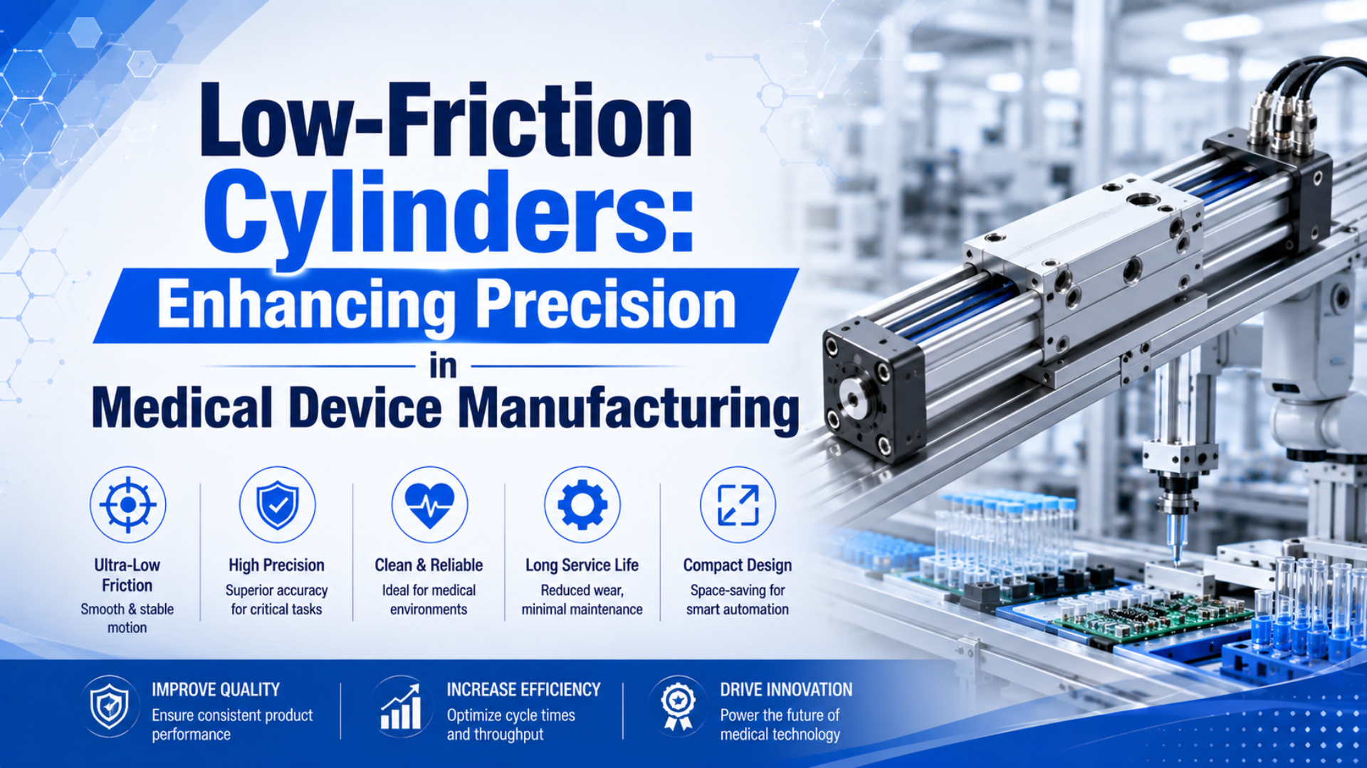
A low-friction cylinder is a pneumatic actuator designed to reduce breakaway and running resistance during controlled motion. Low-friction cylinders for medical device manufacturing can support smooth low-speed motion or contact-force control. They do not guarantee positioning accuracy. Accuracy still depends on the valve, regulator, guide, load, sensor, controller, mounting, and acceptance test.
That distinction matters in medical device manufacturing. SMC publishes a 0.5 mm/s minimum piston speed for its CQ2X low-speed cylinder and a 0.001 MPa lower operating-pressure boundary for its single-acting MQP force-control series. Those figures describe specific models, not a universal tolerance for every low-friction cylinder.
This guide shows how to turn catalog data into a defensible specification for assembly, test, dispensing, handling, and cleanroom equipment. It also shows when servo-pneumatic or electric control should take over.
Smooth motion is not measured position.
Key Takeaways
- Low friction can improve motion and force control, but it does not create position feedback, closed-loop correction, or automatic accuracy.
- CQ2X reaches 0.5 mm/s.
- Cleanroom suitability requires model-level particle evidence and installed-equipment assessment.
- Validate speed, force, position, leakage, particles, and the full circuit on the actual machine.
Do not rely on a universal FDA tolerance, unverified customer stories, or product-performance numbers without matching test records. Every numeric specification should stay tied to a named series, source, and operating condition.
What Does Low Friction Actually Improve?
Low friction primarily lowers the pressure and force needed to start or sustain motion. In its current MQQ/MQM/MQP catalog, SMC lists operating-pressure floors from 0.001 MPa for MQP to 0.005 MPa for MQQT, demonstrating that the result is series-specific rather than a generic pneumatic-cylinder property (SMC MQQ/MQM/MQP catalog, retrieved 2026).
 Photo: TECNIC Bioprocess Solutions via Unsplash. A cleanroom classification applies to the controlled environment; equipment suitability still needs its own evidence.
Breakaway resistance is the force that must be overcome before the piston begins to move. If seal adhesion and sliding resistance are high, pressure rises while the piston remains still and the axis can jump when available force finally exceeds resistance. That jump is the stick-slip behavior low-friction designs are intended to reduce.
The distinction is easy to miss.
The useful benefit depends on the job. A contact roller needs stable force. A pipette fixture may need a gentle approach. A test nest may need repeatable clamping without damaging a molded part. None of those requirements automatically means the piston must stop at an arbitrary point with encoder-level accuracy.
The practical specification is therefore not “high precision cylinder.” It is a measurable operating window: minimum stable speed, available force at the regulated pressure, allowable lateral load, leakage, sensor behavior, and the acceptable variation for the installed process. This wording prevents a smooth-running component from being mistaken for a complete positioning system.
The model code comes first.
Catalog boundaries are not acceptance results.
Which Published Specifications Matter Most?
Start with the exact series code because catalog limits vary by more than one order of magnitude. SMC lists MQQT at 0.3 to 300 mm/s, MQML at 0.5 to 1,000 mm/s, and CQ2X at 0.5 to 300 mm/s (SMC low-friction catalog and SMC CQ2X catalog, retrieved 2026).
Record the following data before comparing suppliers:
- Minimum and maximum piston speed: Confirm the bore, load, orientation, pressure, and circuit conditions behind the range.
- Minimum operating pressure: Treat it as a catalog boundary, not the pressure that guarantees stable movement in every installation.
- Force-control range: Separate controlled thrust from theoretical piston force.
- Leakage: Metal-seal low-friction designs may permit leakage that would be unusual for an elastomer-sealed standard cylinder. Record the supplier’s test pressure, temperature, and reference-air convention.
- Lateral-load allowance: A side load can add friction and erase the behavior the special seal was selected to provide.
- Cushion and kinetic-energy limit: Low friction does not absorb the moving load at the stroke end. Check payload mass, tooling mass, speed, and the permitted impact energy for the exact cushion option.
Leakage can be intentional.
SMC’s MQP series illustrates why the model code matters. Its catalog assigns different thrust-control ranges to each bore: 0.01 to 8 N at 4 mm and 0.30 to 200 N at 20 mm. The manufacturer also states that actual control depends on piston area and pressure accuracy.
Pressure accuracy sets the force floor.
Do not compare those values with a supplier’s theoretical force table as though they describe the same test. The theoretical relationship is pressure multiplied by effective piston area. Real controlled force also includes regulator error, pressure loss, seal resistance, moving mass, gravity, acceleration, guide friction, and contact geometry.
Can a Low-Friction Cylinder Deliver Precise Positioning?
A low-friction cylinder can improve motion consistency, but it cannot promise a universal positioning tolerance. Festo’s 2026 DSNU data sheet lists “low friction” and “uniform, slow movement” as configurable variants while separately identifying proximity-switch position detection, showing that friction, motion, and position feedback are different functions (Festo DSNU data sheet, 2026).
Endpoint work can be highly repeatable when the load stops against a designed mechanical datum and a switch confirms the final state. Mid-stroke stopping is harder. Compressed air is elastic, valve flow changes with pressure ratio, the load may vary, and an open-loop cylinder has no measurement of the remaining position error.
Mid-stroke work needs deliberate position feedback. Our guide to pneumatic cylinder position sensing separates endpoint switches, zones, analog transducers, magnetostrictive sensors, and encoders. A sensor can measure position, but it still needs a suitable control architecture if the cylinder must correct error.
Feedback changes the architecture.
The honest medical-manufacturing claim is not “the cylinder achieves 0.01 mm.” It is “the installed axis met the defined acceptance band for this load, speed, fixture, sensor, pressure, and test method.” That sentence is longer, but it is traceable. It also survives a supplier change because the process requirement remains measurable.
For applications with several commanded positions, study servo-pneumatic positioning architecture before assuming a low-friction seal is enough. If the process requires stiff, fast, multi-position motion with a tight following-error limit, the comparison with electric actuators and cylinders may point to an electric axis.
Cleanroom Suitability Requires Equipment-Level Evidence
Equipment suitability is evidence that machinery can operate within the cleanliness requirements of its intended environment. It cannot be assigned from the words “low friction.” ISO 14644-14:2026 defines a method based on airborne particle concentration, while ISO 14644-1:2015 classifies air using particles from 0.1 to 5 micrometres (ISO 14644-14, 2026; ISO 14644-1, 2015).
An exact clean-series code can carry useful evidence. SMC’s CG1 clean-series catalog lists Class 4 for its 10- configuration, Class 5 for 21-, and Class 3 for 11- or 22- variants. It also distinguishes fluorine grease from lithium-soap grease and warns that exceeding specified strokes may invalidate the particle-generation class (SMC clean CG1 catalog, retrieved 2026).
Particles are measured, not assumed.
That catalog example does not make every cylinder suitable for those classes. Check the complete assembly:
- Confirm whether the model uses a relief port or vacuum suction and where that line exhausts. Include the exhaust path, tubing material, connection method, and maintenance access in the review.
- Record lubricant chemistry, exposed materials, seals, coatings, and cleaning-agent compatibility.
- Review fittings, silencers, switches, cable jackets, guides, shock absorbers, and external grease.
- Test the equipment in the operating state, including realistic speed, stroke, load, and maintenance condition.
- Keep particle suitability separate from cleanability.
Cleanroom claims need operating-state evidence.
Installation can invalidate component evidence.
Exhaust can contaminate the process. Review the applicable ISO compressed-air quality classes and choose filtration from measured risk. A coalescing filter can address aerosols, but it does not replace particulate, dew-point, material, or microbial controls.
Which Medical Device Manufacturing Tasks Fit Low-Friction Cylinders?
Low-friction cylinders fit tasks where smooth low-speed motion or controlled contact force matters more than arbitrary multi-position accuracy. The SMC MQP catalog spans 0.01 to 200 N across five bores, making force-sensitive fixtures a more defensible application than the unsupported claim that every unit provides sub-millimetre positioning (SMC MQP catalog, retrieved 2026).
For example, good candidate tasks include:
- bringing a test probe into contact without a hard impact;
- maintaining light pressure on a roller, membrane, or flexible component while a calibrated load cell verifies the process force;
- clamping molded parts where excessive force can distort the measurement;
- advancing a dispenser at verified low speed;
- transferring a fixture between two hard stops with endpoint confirmation, then recording both switch state and contact with the mechanical datum.
Poor candidate tasks include free mid-stroke positioning without feedback, precision metrology based only on piston location, high side-load motion without a guide, and any installation where the supplier cannot document materials or particle behavior. The process risk, not the marketing label, should decide the technology.
A hard stop changes the control problem.
The same distinction applies to implantable-device production. A pneumatic component may be part of the manufacturing equipment, but it does not confer compliance on the finished device. ISO 13485:2016 defines a quality-management framework, while the current FDA QMSR requires manufacturers to establish an appropriate quality system. Neither source specifies a universal cylinder tolerance.
Force control still needs calibration.
How Should Engineers Size Low-Friction Cylinders for Medical Device Manufacturing?
Begin with force and speed, then add margin for friction and variation. SMC states that CQ2X supports 0.5 to 300 mm/s, but its catalog also warns that low-pressure stability depends on load and that maximum speed can be limited by the circuit or operating pressure (SMC CQ2X catalog, retrieved 2026).
For a double-acting cylinder, calculate theoretical extension force from piston area and pressure. On retraction, subtract the rod area. Then account for the regulated pressure at the cylinder, guide friction, seal behavior, gravity, acceleration, process contact force, and the safety factor appropriate to the machine risk. The walkthrough on force from pressure and area provides the base equations.
In our experience, the best low-speed specification states both the target speed and the available force at that speed. We found that a speed value alone hides regulator droop, tubing loss, and load variation. Recording those conditions early gives the commissioning team a repeatable test instead of a subjective judgment that motion “looks smooth.”
Speed control must follow the manufacturer’s circuit guidance. Low-friction and force-control circuits may use a precision regulator, differential pressure, meter-in flow control, or a dedicated arrangement rather than a generic meter-out circuit. Compare meter-in and meter-out control and verify the chosen method on the actual series manual.
Don’t choke the axis into stability. Undersized valves, long small-bore tubing, regulator droop, trapped volume, and exhaust restriction can create delay and pressure cycling. Use the pneumatic flow-rate calculation guide to check the flow path before blaming the cylinder.
The circuit can erase the cylinder’s advantage.
The calculator is a screening tool. It cannot predict stick-slip, regulator response, seal breakaway, guide friction, particle emissions, or cleanroom suitability in the installed machine. Record those items separately in the component specification and validation protocol.
Acceptance Testing: Measure the Installed Axis
An acceptance test must reproduce the actual load and operating environment. Use the specified pressure and speed. Run the full stroke. Current 21 CFR Part 820 requires an appropriate quality management system and may require test records. It does not prescribe a universal 0.001-inch actuator tolerance (21 CFR Part 820, current 2026).
Build the protocol around the process failure mode:
| Requirement | Test method | Record |
|---|---|---|
| Smooth start | Command motion after defined dwell times | Breakaway pressure, delay, overshoot |
| Low-speed travel | Measure displacement against time | Mean speed, velocity ripple, stalls |
| Contact force | Use a calibrated load cell | Peak, steady value, drift, cycle variation |
| Endpoint repeatability | Measure against the machine datum | Distribution, not only best result |
| Leakage | Apply the supplier’s stated method | Pressure, temperature, measured leakage |
| Clean suitability | Follow the approved particle protocol | Operating state, locations, size channels |
| End-of-stroke behavior | Test maximum credible moving mass | Impact, rebound, cushion setting |
A low-friction-cylinder acceptance result is only portable when the test boundary is recorded. Record the model code, bore, and stroke. Add orientation and load. Name the guide, valve, and tubing. Measure supply pressure and pressure at the cylinder. Include commanded speed, dwell time, sensor resolution, ambient condition, and cycle count. Report the distribution of speed, force, or endpoint measurements rather than one best cycle. For clean equipment, add particle sizes and sampling locations. State the operating condition, background count, and exact ISO 14644 method. These details let another engineer reproduce the result and compare a replacement. They also separate component behavior from machine behavior and prevent a catalog minimum from being misreported as the validated capability of the complete medical-device manufacturing process during formal audit.
Run enough cycles to expose warm-up, regulator drift, seal conditioning, and variation after a dwell. Define acceptance limits before testing. If the first protocol is written after the data arrive, it becomes too easy to rationalize an unstable result.
Write the limits before testing begins.
Validation belongs to the installed process.
The machine owns the final result.
Repeatability needs a defined datum.
Separate component qualification from process qualification. Component evidence proves that the ordered cylinder matches its catalog and material requirements. Process evidence proves that the complete machine performs its manufacturing step. This split makes a future replacement review faster because engineers can see which claims belong to the cylinder and which belong to the installed system.
For impact-sensitive axes, review pneumatic cylinder cushioning independently. A seal designed for low sliding resistance does not remove the kinetic energy of the payload, tooling, and moving piston at the end of the stroke.
When Should You Choose Another Actuator Strategy?
Choose another strategy when the process requirement exceeds what an open-loop low-friction cylinder can prove. Festo’s 2026 DSNU sheet treats low friction, slow movement, and position detection as separate options, while SMC publishes distinct low-speed, low-friction, clean, and force-control families. The architecture must match the controlled variable (Festo, 2026; SMC, retrieved 2026).
| Process requirement | Better starting point |
|---|---|
| Two endpoints, gentle motion | Low-speed or low-friction cylinder with switches |
| Stable contact force | Low-friction cylinder plus precision pressure regulation |
| Several commanded positions | Servo-pneumatic axis with continuous feedback |
| Tight path control and high stiffness | Electric servo actuator |
| Clean environment | Documented clean-series actuator and equipment assessment |
| Significant side load | Guided actuator or external guide with verified alignment |
This is not a ranking from cheap to expensive. It is a control decision. A low-friction cylinder can be the simplest reliable answer for soft contact and two-position work. It becomes an expensive mistake when the process really needs closed-loop position, velocity, or force control and the surrounding hardware is omitted from the specification.
Control architecture follows the measured variable.
Selection starts with the controlled variable.
FAQs About Low-Friction Cylinders in Medical Manufacturing
These five answers replace unsupported promises with measurable boundaries. The key published figures are SMC’s 0.5 mm/s CQ2X minimum speed, MQP’s 0.001 MPa pressure floor, and ISO 14644-14:2026 equipment-assessment scope; none creates a universal medical-device accuracy or cleanroom claim (SMC, retrieved 2026; ISO, 2026).
What positioning accuracy can a low-friction cylinder achieve?
There is no universal accuracy value. Low friction reduces resistance, but position performance depends on the load, guide, valve, sensor, controller, pressure, and stop design. Festo’s 2026 DSNU sheet lists low friction and position detection separately. Specify an installed-axis acceptance band and test it under production conditions.
Is every low-friction cylinder suitable for an ISO Class 7 cleanroom?
No cylinder is cleanroom-ready by label alone. ISO 14644-14:2026 evaluates equipment suitability by airborne particle concentration. Model evidence still matters. SMC clean-series examples distinguish Class 3, 4, and 5 configurations by exact code, grease, relief, and vacuum arrangement. Review the complete machine rather than assigning Class 7 from the seal description.
Can a low-friction cylinder replace a standard cylinder directly?
Only after checking the complete model code. SMC says several CQ2X dimensions are interchangeable with related standard forms. Pressure limits and cushioning can still differ. The same applies to leakage and seals. Check port size, speed range, clean options, mounting dimensions, rod thread, stroke, switches, load, and the pneumatic schematic before approving a replacement.
Which speed-control method is best for low-speed motion?
Use the method specified for the exact series. Some low-friction force-control circuits use precision regulation or meter-in control when managing contact force at low pressure and low speed. Ordinary cylinders often use meter-out control. SMC’s CQ2X catalog lists 0.5 to 300 mm/s. It also warns that load, pressure, and circuit design can limit stable operation.
How should a medical device manufacturer validate the actuator?
Test the installed axis against predefined process limits. Record breakaway behavior and low-speed variation. Measure contact force and endpoint repeatability. Add leakage, impact, and particle results when applicable. The 2026 FDA QMSR requires an appropriate quality system, but it does not provide a universal actuator tolerance or replace process-specific risk analysis.
Sources
The source list below includes the 2026 FDA QMSR, ISO updates, and current SMC and Festo data covering pressure, speed, force, particles, and sensing. All URLs were checked on July 10, 2026. Keep manufacturer values attached to named series and configurations so standards, catalog limits, and installed-machine acceptance results stay separate.
- FDA, Quality Management System Regulation (QMSR), updated 2026-02-02, retrieved 2026-07-10.
- Electronic Code of Federal Regulations, 21 CFR Part 820, current through 2026-07-08, retrieved 2026-07-10.
- ISO 13485:2016, Medical devices - Quality management systems, confirmed current in 2025, retrieved 2026-07-10.
- ISO 14644-14:2026, Assessment of suitability for use of equipment by airborne particle concentration, published 2026-02, retrieved 2026-07-10.
- ISO 14644-1:2015, Classification of air cleanliness by particle concentration, retrieved 2026-07-10.
- SMC, Low Friction Cylinders MQQ/MQM/MQP, current catalog retrieved 2026-07-10. Used for model-specific pressure floors, driving-speed ranges, force-control limits, leakage notes, and warnings that reference values are not guaranteed outside the stated conditions.
- SMC, Smooth/Low Speed Cylinders CJ2X/CM2X/CQSX/CQ2X/CUX, current catalog retrieved 2026-07-10.
- SMC, Clean Series CG1-Z, current catalog retrieved 2026-07-10. Used for clean-series classes, grease, and particle-generation conditions.
- Festo, DSNU-20 ISO Cylinder Data Sheet, dated 2026-06-06, retrieved 2026-07-10. Used to distinguish low-friction, slow-motion, and position-sensing options.