

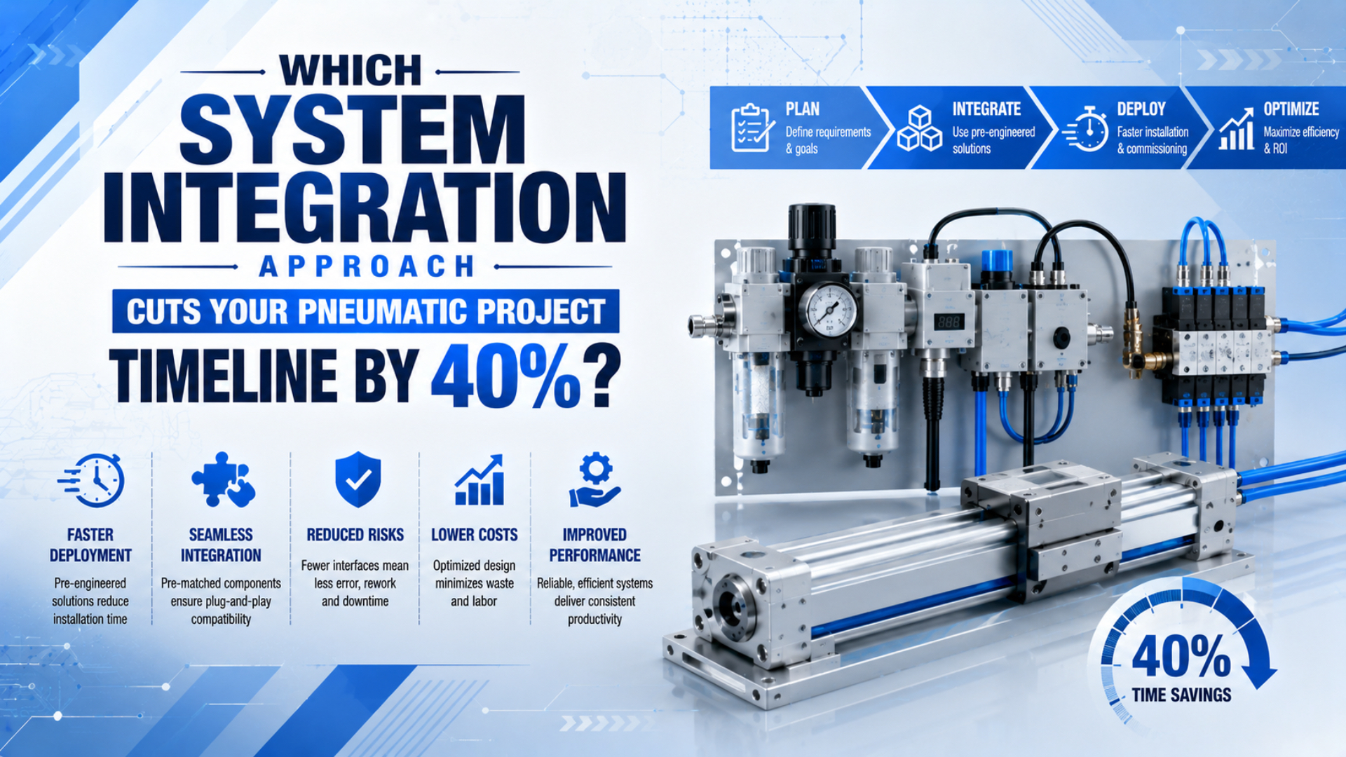
An interface-first, gated pneumatic system integration approach has the best chance of shortening a project because it exposes incompatibilities before hardware reaches the machine. The method freezes requirements, assigns every interface to an owner, verifies component data on the desk, then advances through factory and site acceptance gates.
That is the schedule advantage.
A 40% result is measurable project evidence, not a universal supplier promise. A team may claim it only when the baseline and actual durations cover the same scope, milestones, working calendar, and acceptance criteria. Otherwise, a shorter date may simply hide deferred work.
ISO 4414:2010 places pneumatic-system design in a wider lifecycle that includes construction, modification, installation, adjustment, operation, maintenance, reliability, energy efficiency, and environmental considerations. Matching ports and voltage labels is therefore only a small part of integration (ISO, “ISO 4414:2010”, 2010).
The boundary is broad.
Key Takeaways
- Measure the 40% result against a scope-controlled baseline.
- Freeze requirements first.
- Control mechanical, pneumatic, electrical, data, safety, and service interfaces together.
- Use protocol gateways only after data meaning, timing, diagnostics, failure response, configuration ownership, and restore procedures are defined.
- Close FAT exceptions before site work unless the deviation is formally accepted.
In this guide
- Which integration approach can produce a measured 40% reduction?
- What must be frozen before selecting components?
- Which interfaces belong in the control matrix?
- When should you choose turnkey or multi-vendor architecture?
- How do you use protocol gateways without creating a new failure point?
- What pneumatic performance must be verified before assembly?
- Move through FAT and SAT gates
- Specify the supplier data package
Which Integration Approach Can Produce a Measured 40% Reduction?
The practical answer is a five-gate sequence: baseline, requirements freeze, interface control, factory acceptance, and site acceptance. NASA’s integration-plan guidance separates verification into four methods, analysis, inspection, demonstration, and test, so each requirement can receive evidence before the next costly project stage begins (NASA Systems Engineering Handbook Appendix, 2023).
Calculate schedule reduction as follows:
Here, is the schedule reduction, is the approved baseline duration, and is the duration achieved for the same scope. If a ten-week baseline is completed in six weeks, the measured reduction is 40%.
Keep the boundary honest. Both durations must start and stop at the same milestones. They must include the same engineering, purchasing, assembly, software, testing, documentation, shipment, installation, and acceptance work. A project that removes FAT from the actual duration has not become faster; it has moved risk to the site.
Keep that distinction visible.
These gates are not extra paperwork. They move discovery earlier, when a drawing, parameter file, or test fixture can resolve a mismatch more cheaply than a machine shutdown. Track lead time separately from engineering duration so expedited shipping does not masquerade as better integration.
What Must Be Frozen Before Selecting Components?
A usable verification matrix connects every mandatory requirement to one of four evidence methods: analysis, inspection, demonstration, or test. NASA’s published matrix guidance also calls for a unique identifier and document source for each mandatory requirement, turning vague expectations into traceable acceptance evidence (NASA Systems Engineering Handbook Appendix, 2023).
Begin with the operating envelope, not a preferred brand. Record:
- motion sequence, load, stroke, orientation, speed, cycle rate, and stop behavior;
- minimum pressure at the machine inlet and expected pressure during peak flow;
- air quality at the measurement point;
- ambient temperature, washdown chemistry and pressure, dust, corrosion, vibration spectrum, cleanability, installation height, nearby heat sources, and permitted enclosure protection;
- control voltage, connector pinout, I/O type, update requirement, and diagnostics;
- machinery safety functions, safe state, reset behavior, and restart rules;
- service strategy;
- drawings, declarations, test records, software files, and manuals required at handover.
Use shall only for mandatory requirements. Give each one an acceptance method and pass criterion before issuing the RFQ. “Cylinder must be fast” is not testable. “The loaded extension shall complete within the stated time at the minimum specified inlet pressure, using the approved valve and tubing configuration” is.
Write it down before ordering.
Requirements also need an owner. The machine builder might own the motion profile, the component supplier the catalog limits, the controls integrator the I/O mapping, and the end user the site utility data. If two parties appear to own the same interface, name one decision authority and one reviewer.
Which Interfaces Belong in the Control Matrix?
ISO 4414:2010 explicitly applies to pneumatic-system design, construction, and modification, while also addressing installation, operation, maintenance, reliability, and energy efficiency. An integration matrix should therefore cover at least six interface domains rather than treating component compatibility as one percentage score (ISO, “ISO 4414:2010”, 2010).
An interface control matrix is the working register that links each boundary to its requirement, evidence, owner, status, and change authority. It should complement approved drawings and specifications, not replace them.
| Interface domain | Minimum evidence | Typical hidden mismatch | Decision owner |
|---|---|---|---|
| Mechanical | envelope drawing, mounting pattern, load direction, service clearance | ports or adjusters become inaccessible after installation | mechanical lead |
| Pneumatic | port standard, pressure range, flow data, exhaust path, air quality | nominal port matches, but fitting and tubing restrict peak flow | pneumatic lead |
| Electrical | voltage range, current, connector, pinout, protection | same connector shell carries a different pin assignment | controls lead |
| Data | protocol, device profile, data type, byte order, update rate, diagnostic map | values arrive but units, scaling, or fault codes differ | controls lead |
| Safety | required function, safe state, architecture, validation evidence | ordinary I/O or a standard gateway is placed in a safety path | safety lead |
| Service | removal path, isolation points, spares, backups, restore method | a failed device cannot be replaced without dismantling the machine | maintenance lead |
For each row, record the requirement ID, supplier evidence, responsible owner, status, open action, due date, and change authority. Use pass, conditional pass, or fail. Do not convert safety, protocol, or serviceability into a weighted “compatibility percentage”; a single failed mandatory interface can stop the project even when every other row passes.
One failed interface can be enough.
An Interface Control Document can hold the approved values, while the matrix tracks completion. NASA’s interface-management requirements call for pre-checking physical interfaces before connection, evaluating assembled products for compatibility, and covering internal and external interfaces in verification and validation plans (NASA NPR 7123.1B, updated through Change 4).
When Should You Choose Turnkey or Multi-Vendor Architecture?
ISO 12100:2010 describes risk assessment and risk reduction across relevant machinery lifecycle phases, including documentation and verification. That lifecycle view is a better architecture test than brand count: choose the arrangement whose interfaces, changes, hazards, and acceptance evidence can be controlled by the available project team (ISO, “ISO 12100:2010”, 2010).
A turnkey package is strongest when one supplier can own the complete performance boundary, including valves, actuators, sensors, controls interface, drawings, testing, and corrective action. It becomes weak when “turnkey” excludes site utilities, software, safety validation, or production-load testing. Contract language must say where the supplier’s responsibility starts and ends.
A multi-vendor architecture can be better when an approved component standard, local service requirement, or specialized function outweighs the additional interfaces. It needs stronger configuration control and a named system integrator. Without that owner, each component may meet its own datasheet while the assembled machine still fails its cycle or recovery requirement.
| Decision factor | Turnkey package is favored when | Multi-vendor design is favored when |
|---|---|---|
| Performance ownership | one supplier can warrant the complete motion boundary | the integrator can model and test the complete chain |
| Required specialization | standard package meets the operating envelope | a specialist component provides a necessary function |
| Controls environment | supplied interface matches the plant standard | the plant has a mature, enforced controls standard |
| Service strategy | one support route is valuable | approved local spares and skills dominate |
| Change frequency | scope is stable | modular substitution is planned and controlled |
| Evidence | supplier provides complete FAT and data package | integrator owns the combined verification matrix |
Do not choose turnkey merely to reduce purchase-order count. Do not choose multi-vendor merely to reduce component prices. Compare the cost and schedule of interface definition, adapters, software mapping, testing, documentation, spares, and fault ownership.
Ownership matters more.
How Do You Use Protocol Gateways Without Creating a New Failure Point?
An IO-Link IODD records device identity, parameters, process data, diagnostic data, and communication characteristics. Those five information groups illustrate why protocol conversion is not enough: a gateway may transport bytes, but commissioning still needs a controlled description of what the bytes mean and how the device should behave (IO-Link Community, “IODD”, accessed 2026-07-27).
Bytes are not meaning.
Map the communication interface before selecting a gateway:
- Record both protocols and physical media.
- List every exchanged variable with source, destination, data type, byte order, scaling, engineering unit, valid range, and update requirement.
- Define command acknowledgement, stale-data detection, timeout, startup state, warm restart, cold restart, power-cycle behavior, and the exact machine response to lost or corrupted communication.
- Map diagnostics to actions.
- State who owns the gateway configuration, firmware, backup, restore test, and replacement procedure.
Measure end-to-end behavior using the actual PLC task, network load, gateway configuration, valve terminal, and device set. A gateway’s catalog latency is not the actuator response time. End-to-end delay also includes controller scan, network update, valve switching, pressure buildup, tubing volume, cylinder motion, sensor response, and logic confirmation.
Keep ordinary protocol gateways outside a machinery safety function unless the complete safety-related architecture is designed and validated for that purpose. ISO 13849-2:2012 requires validation by analysis and testing of specified safety functions, achieved category, and performance level; a familiar connector or protocol name does not provide that evidence (ISO, “ISO 13849-2:2012”, 2012).
The ISO 13849 pneumatic safety-circuit guide explains how PLr, architecture, reliability data, diagnostics, and validation apply to the complete safety function.
A gateway is also an OT asset. Include it in network diagrams, access control, configuration backups, firmware management, and incident recovery. NIST SP 800-82 Rev. 3 addresses OT security while preserving performance, reliability, and safety requirements, which is the right balance for a device placed between control networks (NIST, “Guide to Operational Technology Security”, 2023).
What Pneumatic Performance Must Be Verified Before Assembly?
ISO 6358-1:2013 defines steady-state testing for compressible-fluid components with fixed or variable internal flow paths. It excludes cylinders, accumulators, regulators with internal feedback, and components with unstable flow coefficients, so engineers must use the right component data and then validate the assembled motion separately (ISO, “ISO 6358-1:2013”, 2013).
Start with the required motion profile. Calculate cylinder volume and free-air demand, then check the complete supply and exhaust path: regulator, shut-off valve, manifold, directional valve, fittings, tubing, silencers, and quick-exhaust devices where used. Compare flow data only when the reference pressure, downstream condition, temperature, and standard-volume convention are compatible.
Pressure at the machine inlet is not pressure at the cylinder chamber. Estimate or measure the drop during the worst simultaneous demand. Long, small-bore tubing adds restriction and dead volume; oversized remote valves can still produce a slow response. The related guides on pressure-drop diagnosis and tubing and fitting configuration cover those checks in more detail.
Compressed-air quality must also be specified at a measurement point. ISO 8573-1:2010 separates purity classes for particles, water, and oil, rather than defining one generic “clean air” grade (ISO, “ISO 8573-1:2010”, 2010). Match the target to the most sensitive validated component and process requirement.
Use a desktop or bench test to close the high-risk items:
- verify valve and sensor pinouts with the approved cables;
- load the exact released configuration, power-cycle every device, and confirm that automatic identification does not mask an incorrect parameter set;
- simulate communication loss, corrupted or stale data, air loss, power loss, emergency stop, controlled stop, reset, warm restart, and cold restart;
- record dynamic pressure near the actuator;
- run the intended cycle with representative load and tubing;
- confirm sensor margins;
- inspect exhaust noise, back pressure, heat, vibration, and service access.
Test the assembled path.
For circuit architecture, the industrial pneumatic system components guide helps define the supply-to-actuator boundary, while the sequential cylinder circuit guide shows how commands, completion signals, timeouts, and fault responses fit together.
Move Through FAT and SAT Gates
NASA’s verification and validation outline uses four evidence methods and distinguishes end-item integration from complete-system integration. That distinction maps well to pneumatic projects: bench checks prove individual interfaces, FAT proves the assembled machine under controlled conditions, and SAT confirms the installed system with actual utilities and production constraints (NASA Systems Engineering Handbook Appendix, 2023).
What should FAT prove?
Factory acceptance testing should use an approved procedure tied to requirement IDs. Test normal cycles, minimum and maximum permitted settings, representative loads, changeover, diagnostics, air and power loss, blocked or missing sensors, communication loss, controlled stop, reset, restart, and maintenance isolation.
Record the software and configuration versions, instruments, calibration status, inlet conditions, load, cycle count, results, deviations, evidence files, and signatures. If production material or site utilities are unavailable, state the simulation and create a named SAT item. “Tested successfully” is not enough for later troubleshooting.
What should SAT prove?
Site acceptance confirms what the factory could not reproduce: installed air capacity and purity, real network topology, production load, upstream and downstream interlocks, environmental exposure, guarding, safe isolation, operator procedures, maintainability, and recovery after site-specific faults.
Do not turn SAT into unfinished assembly. A FAT exception may move forward only when the responsible owner, technical risk, containment, closure evidence, due date, and approval authority are documented. Safety-related exceptions require the treatment defined by the project’s safety lifecycle, not an informal schedule waiver.
How should change control work?
After requirements freeze, every change should identify the affected drawing, bill of materials, software, parameters, spares, manuals, test cases, and acceptance records. Re-run the impacted verification rather than the whole project blindly. This makes change control a schedule tool: it prevents a local substitution from silently invalidating downstream evidence.
Specify the Supplier Data Package
NASA’s interface-management process requires controlled interface documents or drawings, formal change procedures, and traceability across each affected boundary. A pneumatic RFQ does not need NASA terminology, but it does need the same result: approved interface information that becomes part of the technical data package (NASA NPR 7123.1B, updated through Change 4).
Request deliverables by milestone:
| Milestone | Required evidence |
|---|---|
| Quotation | compliance matrix, exclusions, deviations, lead time, responsibility boundary |
| Design review | dimensioned drawings, port and thread data, load limits, circuit, I/O list, network architecture |
| Pre-FAT | approved bill of materials, software and configuration versions, test procedure, instrument list |
| FAT release | signed results, deviation log, backup files, final settings, photographs where useful |
| Shipment | as-built drawings, declarations, manuals, spare-parts list, preservation and packing records |
| SAT and handover | installed test results, open-item closure, training record, maintenance and restore procedures |
Put document approval dates ahead of manufacturing release. A long-lead component should not be ordered against an unresolved mounting, flow, voltage, or safety interface merely because its catalog description looks close.
Service follows the same principle. Require a known replacement configuration, backed-up parameters, restore instructions, and a functional check after replacement. If the system depends on one specialist’s laptop or memory, the project is not fully integrated.
Conclusion
ISO 4414 covers pneumatic systems across design, installation, operation, maintenance, reliability, and efficiency, while NASA’s interface guidance connects controlled interfaces to verification and validation. Together they support a clear conclusion: schedule compression comes from earlier evidence and firmer ownership, not from skipping acceptance work or buying a gateway (ISO 4414, 2010).
An interface-first gated approach can produce a measured 40% reduction when it prevents rework on the project’s critical path. Establish the baseline, freeze testable requirements, close interface risks on the desk, verify the assembled machine at FAT, and reserve SAT for site-dependent evidence. Report the result only after the same-scope comparison is complete.
Pneumatic System Integration FAQs
ISO 13849-2 requires safety-function validation by analysis and testing, while NASA’s integration outline uses analysis, inspection, demonstration, and test across progressively integrated products. These sources reinforce the same practical rule: purchasing, communication, performance, and safety evidence must be assigned before a pneumatic project can pass from one integration gate to the next (ISO 13849-2, 2012).
Does a turnkey package automatically shorten the project?
No. It shortens the project only when one supplier accepts a clear system boundary and provides compatible hardware, software, documentation, testing, and corrective action. If site utilities, safety validation, production-load testing, or controls mapping remain excluded, the buyer still owns those interfaces and must include them in the schedule. Read the exclusions.
When should we use a protocol gateway?
Use a gateway when two required networks cannot communicate directly and the team can define every exchanged variable, timing requirement, diagnostic, timeout, and recovery action. Select it after completing the data map. A gateway that translates frames without controlled data meaning can move the commissioning problem instead of solving it.
What should be completed before FAT?
Approve the requirements matrix, interface control data, drawings, bill of materials, I/O map, network architecture, software versions, settings, test procedure, instruments, representative load, and expected fault responses. Open design questions should have named owners and closure dates; unresolved safety blockers should not enter formal factory acceptance testing.
How do we calculate a 40% timeline reduction?
Subtract the actual same-scope duration from the approved baseline, divide by the baseline, and multiply by 100%. A ten-week baseline completed in six weeks produces a 40% reduction. Use identical start and finish milestones, working calendars, deliverables, and acceptance criteria so deferred work is not counted as saved time.
Can a standard gateway carry a machinery safety function?
Not by default. The complete safety-related control architecture, including communication, logic, outputs, pneumatic elements, diagnostics, and fault response, must meet the required design and validation criteria. Ordinary protocol support or successful data exchange does not prove the achieved category, performance level, or validation of the safety function.
Sources and technical references
- ISO 4414:2010, Pneumatic fluid power: General rules and safety requirements for systems and their components. Published 2010. Retrieved 2026-07-27.
- ISO 6358-1:2013, Determination of flow-rate characteristics using compressible fluids. Published 2013. Retrieved 2026-07-27.
- ISO 8573-1:2010, Compressed air contaminants and purity classes. Published 2010. Retrieved 2026-07-27.
- ISO 12100:2010, Safety of machinery risk assessment and risk reduction. Published 2010. Retrieved 2026-07-27.
- ISO 13849-2:2012, Validation of safety-related parts of control systems. Published 2012. Retrieved 2026-07-27.
- NASA Systems Engineering Handbook Appendix. Includes verification matrices and an integration-plan outline. Retrieved 2026-07-27.
- NASA NPR 7123.1B, Systems Engineering Processes and Requirements. Interface-management and product-integration requirements. Retrieved 2026-07-27.
- IO-Link Community, IODD: The Heart of IO-Link. Device identity, parameter, process, diagnostic, and communication descriptions. Retrieved 2026-07-27.
- NIST SP 800-82 Rev. 3, Guide to Operational Technology Security. Published 2023. Retrieved 2026-07-27.